Eiki EIP-25 Service Manual
Hide thumbs
Also See for EIP-25:
- Owner's instruction manual (32 pages) ,
- Owner's instruction manual (33 pages)
Table of Contents
Advertisement
Quick Links
SERVICE MANUAL
For your convenience, all service parts, identified in this manual are available through Eiki's normal distribution
channels. In addition to service part number, the generic descriptions have been give, where possible, to allow
your service technicians to substitute equivalent components which might be available from other sources.
All orders for service parts will be honored. However, in instances where generic components are considered to
be available from several common sources, as would be the case with an industry standard fuse, resistor, or
semiconductor, it may be more economical and expeditious to purchase the part locally.
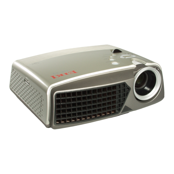
Multimedia Projector
FOREWORD
Model No. EIP-25
Chassis No.: 4121012021
Issue Date:
2004/3/17
Version:
B.5
Advertisement
Table of Contents

Related Manuals for Eiki EIP-25


Summary of Contents for Eiki EIP-25
- Page 1 Version: FOREWORD For your convenience, all service parts, identified in this manual are available through Eiki’s normal distribution channels. In addition to service part number, the generic descriptions have been give, where possible, to allow your service technicians to substitute equivalent components which might be available from other sources.
-
Page 2: Table Of Contents
EIP-25 Projector CHASSIS NO. 4121012021 Contents █ █ Safety Instructions _____________________________________________________ 2 █ Specifications_________________________________________________________ 3 █ Adjustments after Parts Replacement ______________________________________ 4 █ Circuit Protections _____________________________________________________ 5 ● Fuse ________________________________________________________ 5 ● Thermal switch ________________________________________________ 5 ● Interlock switch ________________________________________________ 5 ●... -
Page 3: Safety Instructions
EIP-25 Projector CHASSIS NO. 4121012021 Safety Instructions █ SAFETY PRECAUTIONS WARNING: The chassis of this projector is isolated (COLD) from AC line by using the converter transformer. Primary side of the converter and lamp power supply unit circuit is connected to the AC line and it is hot, which hot circuit is identified with the line ( ) in the schematic diagram. -
Page 4: Specifications
EIP-25 Projector CHASSIS NO. 4121012021 Specifications █ Projection System DLP (Digital Light Processor) Panel 0.7” DMD x 1/DDR Native Resolution 1024x768 Resolutions Supported 640x480, 800x600,1024x768, and 1280x1024 Input Sources D-sub(RGB), D-sub(Y, Pb, Pr), Component RGB(Y, Cb, Cr), RCA Video/Audio, S-video, PC Audio, IR... -
Page 5: Adjustments After Parts Replacement
EIP-25 Projector CHASSIS NO. 4121012021 Adjustments after parts replacement █ A : Adjustment necessary C : Check necessary Disassembly / Replaced Parts DMD/Driver Board Main Board Optical Mirror Adjustments Color index adjustment test Electrical Calibration Adjustments Reset all RGB_Analog Reset all DVI... -
Page 6: Circuit Protections
EIP-25 Projector CHASSIS NO. 4121012021 Circuit Protections █ ● Fuse The fuse is located on the power supply board. It can’t replace it alone. Please replace power supply. ● Thermal switch There is the thermal switch inside of the projector to prevent the internal temperature rising abnormally. -
Page 7: Mechanical Disassemblies
EIP-25 Projector CHASSIS NO. 4121012021 Mechanical Disassemblies █ 1. Cabinet top removal (1) Remove 2 screw A (M3x 80), 2 screw B (M3x10), 1 screw C (M2.6x8) to take the cabinet top assy upward off. Screw A 7110230802 Screw B 7110430103... - Page 8 EIP-25 Projector CHASSIS NO. 4121012021 2. Focus ring AL removal (1) Remove 3 screws A (M2x4) to take the Focus ring AL Off Screw A 7110820043 Focus Ring AL 7535700006...
- Page 9 EIP-25 Projector CHASSIS NO. 4121012021 3. Front panel and Adjuster leg assy removal (1) Remove 4 screws A (T3x6) to take the adjuster leg assy off. (2) Remove 3 screws B (T3x6), C (m3x10) take the Front panel assy off...
- Page 10 EIP-25 Projector CHASSIS NO. 4121012021 4. I/O Board assy removal (1) Pull the I/O Board assy upward. and disconnect the I/O board connector. (2) Remove 4 screws A (T2.6x8), 6 screws B (hex #4-40UNC) to take the I/O Board off.
- Page 11 EIP-25 Projector CHASSIS NO. 4121012021 5. Fan (80x80) assy removal (1) Remove 1 screw A (T3x6), 1 screw B (M3x10) to take the Fan assy (80x80) off (2) Take the 2 Fan w/rubber holder Off From the Grille assy. (3) Take the 2 Fan (80x80) from Rubber holder.
- Page 12 EIP-25 Projector CHASSIS NO. 4121012021 6. Power Board .Ballast Board .Blower .AC Inlet w/sw. removal (1) Remove 2 screw A (M2.5x6) and disconnect the lamp ballast socket. (2) Remove 6 screws B (T3x6) to take the POWER assy off. Screw A 7110625043...
- Page 13 EIP-25 Projector CHASSIS NO. 4121012021 (3) Remove 4 screw C (M3x6) and take the Ballast Board off. (4) Remove 4 screw C (M3x6) and take the Powert Board off. (5) Remove 2 screw D (M3x22) and take the Blower off.
- Page 14 EIP-25 Projector CHASSIS NO. 4121012021 7. Fan (70x70) assy removal (1) Remove 3 screw A (T3x6) and take Fan (70x70) assy off. (2) Remove 2 screws B (M3x22) to take the Fan (70x70) w/rubber holder off. (3) Take the Fan (70x70) from Rubber holder.
- Page 15 EIP-25 Projector CHASSIS NO. 4121012021 8. Optical Unit removal (1) (1) Remove 1 screw A (M3x6) to take the Lamp Cover off. (2) Loosen 3 screw B (M2.5x6) to take the Lamp assy by pulling the handle. Screw A 7110630063...
- Page 16 EIP-25 Projector CHASSIS NO. 4121012021 9. Optical Unit removal (2) (1) Remove 10 screw C (M2.6x8) to take the Optical unit upward off. Screw C 7140226082 Thermal Switch 6853010500...
- Page 17 EIP-25 Projector CHASSIS NO. 4121012021 10. Main Board removal (1) Remove 4 screws A(T3x6) to take the Main Board upward off. Screw A 7140430062 MAIN BD 5173300021...
- Page 18 EIP-25 Projector CHASSIS NO. 4121012021 11. In lock sw Board and D-Sub jack assy removal (1) Remove 1 screw A (T2x4) to take the Inlock sw Board. (2) Remove 3 screws B (T3x6) to take the D-sub jack assy. Screw A 7141220043...
-
Page 19: Optical Parts Disassemblies
EIP-25 Projector CHASSIS NO. 4121012021 Optical Parts Disassemblies █ 1. Lamp Door & Lamp assy removal (1) Remove 1 screw A (M3x6) to take the Lamp Door off. (2) Remove 3 screws B (M2.5x6) to take the Lamp assy off. - Page 20 EIP-25 Projector CHASSIS NO. 4121012021 2. Optical Engine Assy removal (1) Remove the Cabinet top, Focus ring AL, Front panel. following to " Mechanical Disassemblies Item 1.2.3. (2) Remove 10 screws B (T2.6x8) to take the Optical Engine Assy off.
- Page 21 EIP-25 Projector CHASSIS NO. 4121012021 3. Lamp Cover assy & UV IR Cut assy removal (1) Remove 2 screws A (M2.5x6) to take the Lamp Lamp Cover assy off. (2) Unhook 2 hook B and take the UV IR cut assy off.
- Page 22 EIP-25 Projector CHASSIS NO. 4121012021 4. Optical Engine Top cover and Projection Lens removal (1) Remove 7 screw A (M2.5x4) to take the Engine top cover off. (2) Remove 2 screws B (M3x6) to take the Projection Lens off. Screw A 7110625043...
- Page 23 EIP-25 Projector CHASSIS NO. 4121012021 5.Color wheel assy and Rod assy removal (1) Remove 2 screws A (M2.5x4) to take the Color wheel assy off. (2) Remove 2 screws B (M2.5x4) to take the Rod assy off. Screw A 7110625043...
-
Page 24: Lamp Replacement
EIP-25 Projector CHASSIS NO. 4121012021 Lamp Replacement █ When the lamp is within 30 hours of maximum lamp life, projector will display a warning automatically stating, “Lamp has reached its end of life! Lamp replacement is suggested!”. When this message appears, please change the lamp immediately. -
Page 25: Cleaning
EIP-25 Projector CHASSIS NO. 4121012021 Cleaning █ Please follow the following procedures to clean the projector lens: 1 Pour out a little cleaner on a clean soft cloth. Do not use the cleaner with particle, the cleaner that contains solvent or other chemicals of poor quality, they may cause damage to the projector lens. -
Page 26: Optical Adjustment
EIP-25 Projector CHASSIS NO. 4121012021 Optical Adjustment █ Mirror Frame Mark screw A,B,C Projecting full white pattern on the screen. Tighten the screw A, B and C. Loosen the screw B based on 3.5 cycles. Then loosen screw A to control the white pattern to move to left. Until the left and right dark side disappear. -
Page 27: Electrical Adjustment
EIP-25 Projector CHASSIS NO. 4121012021 Electrical Adjustments █ ● Color index adjustment test Required equipment Chroma2326 1. Switch the frame to WRGB 64 level. Note: 256 Steps for W.R.G.B is required. 2. Check the White, Red, Green and Blue colors of frame are correct and smooth-going. - Page 28 EIP-25 Projector CHASSIS NO. 4121012021 ● Reset all RGB_Analog Required equipment Chroma2326 1. RP133 pattern 1024 x 768 60HZ Note: White line is required in periphery. 2. Press “Menu” key and execute “Reset all” in Management. ● Reset all DVI...
-
Page 29: Block Diagrams And Waveform
EIP-25 Projector CHASSIS NO. 4121012021 Block Diagrams and Waveform █ 【1】 schematic diagram... - Page 30 EIP-25 Projector CHASSIS NO. 4121012021 【1.1】 Main Board and IO Board Block Main Board and Video Board Block Analog MCLK=128MHz Flash ROM Output Port VGA OUTPUT DCLK=60MHz Analog VGA INPUT port AD9883 R/G/B Graphics DVI INPUT Digital port port SDRAM...
- Page 31 EIP-25 Projector CHASSIS NO. 4121012021 【1.2】 Main Board Block Diagram Analog Digital RGB/YUV RGB/YUV D-Sub 9883 Digital TMDS PW164A Analog Video Component S-Video Composite 7118 Analog Video...
- Page 32 EIP-25 Projector CHASSIS NO. 4121012021 【1.3】 AD9883SOG SOG IN Sync. Stripper HS IN SOG OUT HS OUT COAST DATACLK VS IN VS OUT...
- Page 33 EIP-25 Projector CHASSIS NO. 4121012021 【1.4】 The Clamping Circuit 47nF R/G/B X1.23 33~120 Ohm CLAMP AD9883...
- Page 34 EIP-25 Projector CHASSIS NO. 4121012021 【1.5】 TMDS Circuit TMDS R112 8,10 GCLK C148 GRE[0..7] 8,10 GRE7 GRE6 GRE5 GRE4 GRE3 GRE2 Parallel GRE1 Transition GRE0 Digital Data GGE[0..7] 8,10 Minimized GGE7 GGE6 GGE5 QE13 GGE4 QE12 Differential GGE3 QE11 GGE2...
- Page 35 EIP-25 Projector CHASSIS NO. 4121012021 【1.6】 TMDS Block Diagram TMDS Serial data channels & clock Transmitter (Tx) Receiver (Rx) 24 bit data 3 Controls Digital Monitor Pixel Clock...
- Page 36 EIP-25 Projector CHASSIS NO. 4121012021 【1.7】 SAA7718 Block Diagram VIDEO DECODER Composite DEN/HS/VS/VCLK VCLK (yellow) SII504 VidInData Luma S-Video Chroma SAA7118 Component Video 24.576MHz...
- Page 37 EIP-25 Projector CHASSIS NO. 4121012021 【1.7.1】 Video Signal waveform ● Composite Signal ● Y-Signal...
- Page 38 EIP-25 Projector CHASSIS NO. 4121012021 ● C-Signal...
- Page 39 EIP-25 Projector CHASSIS NO. 4121012021 【1.7.2】7118 Block Diagram...
- Page 40 EIP-25 Projector CHASSIS NO. 4121012021 【1.8】SiI504 Block Diagram...
- Page 41 EIP-25 Projector CHASSIS NO. 4121012021 【2】IO Board...
- Page 42 EIP-25 Projector CHASSIS NO. 4121012021 【3】Driver Board Block Diagram Component Set DDP1000 Electronics Block Diagram For XGA/SVGA with DAD1000 RAMBUS RAMBUS 400MHz CLOCK RDRAM 128MBIT (DRCG) 12V - P12V 3.3V - P3P3V 100MHZ 2.5V - P2P5V CRYSTAL JUMPERS OR OSC...
- Page 43 EIP-25 Projector CHASSIS NO. 4121012021 【3.1】Driver Board Component Set Power Supply Distribution Component Set Power Supply Distribution 2.5V Vterm RAMBUS Vref Terminators Customer DRCG CORE, VCCPLL Electronics RDRAM Vref DDP1000 V I/O 3.3V Flash XGA & SXGA (MOSC) (COSC) (USB)
- Page 44 EIP-25 Projector CHASSIS NO. 4121012021 【3.2】Component Set DAD 1000 Component Set DAD1000 SR16 MODE[1:0] SR16 SEL[1:0] SR16 A[3:0] SR16C (00-15) Function SR16 STROBE Contains SR16C functionality & DMD drive voltage generation SR16 OEZ 80 TQFP Thermal Enhanced Package (Same size as 3.3 or 5 volt to 12 volt...
- Page 45 EIP-25 Projector CHASSIS NO. 4121012021 【3.3】Component Set Rambus Short Channel Component Set Rambus Short Channel Only one RDRAM used for DDP1000 short channel Recommend Customers follow Rambus Short Channel Layout Guide PCB layouts should be reviewed for Rambus...
- Page 46 EIP-25 Projector CHASSIS NO. 4121012021 【3.4】Component Set Rambus Clock Topology Component Set RAMBUS Clock Topology Data Clock Terminations Terminator Clock and the data propagate together...
- Page 47 EIP-25 Projector CHASSIS NO. 4121012021 【3.5】Component Set Electronic Color Wheel Alignment Supply feature for OEM to do electronic color wheel alignment. Timing mark is positioned early. Add programmable delay to color wheel index. Define I2C parameter defining color wheel index delay at 120Hz.
- Page 48 EIP-25 Projector CHASSIS NO. 4121012021 【3.6】DLP Lamp on Timing...
- Page 49 EIP-25 Projector CHASSIS NO. 4121012021 【4】Switching Power Design...
- Page 50 EIP-25 Projector CHASSIS NO. 4121012021 【5】Ballast Control...
- Page 51 EIP-25 Projector CHASSIS NO. 4121012021 【5.1】Ballast control signal waveform...
-
Page 52: Troubleshooting
EIP-25 Projector CHASSIS NO. 4121012021 Troubleshooting █ ● Components Allocation A Main PCBA (5173300021) G Thermal Switch (6853010500) B I/O PCBA (5175200001) H Color Wheel C Driver PCBA HV Cable (with Ballast) D Power Supply PCBA (6896220011) J Blower (7537300011-0B) -
Page 53: Power On Problems
EIP-25 Projector CHASSIS NO. 4121012021 ● Power on Problems Problem Solution The lamp doesn’t light up after the projector 1. Check the lamp door is closed and fastened by powers on. screw. The projector turns off automatically in 1. Please disclose the top case to check if all four about 10 seconds after the lamp lights up, fans are running. -
Page 54: Image Quality Problems
EIP-25 Projector CHASSIS NO. 4121012021 ● Image Quality Problems: Problem Solution There are several vertical white lines on a 1. Check Driver PCBA is connected closely. blue screen. 2. Please re-lock the heat sink on Driver. There are smears and spots on projection 1. -
Page 55: Power Problems
EIP-25 Projector CHASSIS NO. 4121012021 ● Power Problems Problem Solution The LED indicator on the control panel 1. Check if the power cord is plugged into the socket doesn’t light. power voltage is 110V/220V. 2. Check if the power supply is connected properly Main PCBA . -
Page 56: Upgrading Osd Software
EIP-25 Projector CHASSIS NO. 4121012021 Upgrading OSD Soft ware █ While you’re repairing the projector, you may need to update projector software. Before upgrading OSD, you may need the following: A. Download Program, Pixelworks Flash Upgrader B. R/S 232 Cable……….. - Page 57 EIP-25 Projector CHASSIS NO. 4121012021 B. Make sure the routine of download program located in computer C. Downloading OSD program (1) Connect AC to the projector. (Do not press Power key now) (2) Switch on the power switch to enter standby mode.
-
Page 58: Power Supply Connector Pinouts
EIP-25 Projector CHASSIS NO. 4121012021 Power Supply Connector Pinouts █ Signal +3.3V +3.3V +3.3V +3.3V +5Vc +5Vc +12Vc +12Vc +12V +12V... -
Page 59: Service Parts List
EIP-25 Projector CHASSIS NO. 4121012021 Service Parts List █ ● Product Tree Diagram 4121012021 Burn-In Assy Packing Assy Projector Assy Engine Assy Main BD Key BD (MI) Th Sensor Door-Lock Driver BD CW BD (MI) IO BD (MI) 5173800021 5174300041... -
Page 60: Parts List
EIP-25 Projector CHASSIS NO. 4121012021 ● Part List ● Electrical Part List CAPACITOR CAP. MC CAP.MC UNIT VOLTAGE TYPE OTHERS CAPACITANCE TOLERANCE CAP. ALU CAP. MER CAP. PEN CAP. PPS CAP. CD CAP. MPA CAP. PER CAP. PS CAP. MC CAP. - Page 61 EIP-25 Projector CHASSIS NO. 4121012021...
- Page 62 EIP-25 Projector CHASSIS NO. 4121012021 CKTID Part Number Description Qty. CKTID Part Number Description Qty. ENGINE ASS'Y-FP520D-01-(K)-NB 0C019 6373410406 CAP. MC-uF-0.1-25V-M-Y5V-SMD-0 00SC1 6628166010 SOCKET-DMD-166PIN-FOXCONN-PE01 0C020 6373410406 CAP. MC-uF-0.1-25V-M-Y5V-SMD-0 0P0S1 6714010900-00 HARNESS-1P-80mm-#22-BLACK-4.4D 0C021 6373410406 CAP. MC-uF-0.1-25V-M-Y5V-SMD-0 0W007 6711031160-00 HARNESS-3PIN-90mm-1517#28+TUBE 0C022 6373410406 CAP.
- Page 63 EIP-25 Projector CHASSIS NO. 4121012021 CKTID Part Number Description Qty. CKTID Part Number Description Qty. 0C057 6371168056 CAP. MC-pF-68-50V-J-NPO-SMD 06 0C531 6373410406 CAP. MC-uF-0.1-25V-M-Y5V-SMD-0 0C058 6373410406 CAP. MC-uF-0.1-25V-M-Y5V-SMD-0 0C532 6373410406 CAP. MC-uF-0.1-25V-M-Y5V-SMD-0 0C059 6373410406 CAP. MC-uF-0.1-25V-M-Y5V-SMD-0 0C533 6373410406 CAP. MC-uF-0.1-25V-M-Y5V-SMD-0...
- Page 64 EIP-25 Projector CHASSIS NO. 4121012021 CKTID Part Number Description Qty. CKTID Part Number Description Qty. 0C568 6373410406 CAP. MC-uF-0.1-25V-M-Y5V-SMD-0 0R015 6252392946 RES. CHIP-R-OHM-39.2-1/10W-F-0 0C569 6373410406 CAP. MC-uF-0.1-25V-M-Y5V-SMD-0 0R016 6252392946 RES. CHIP-R-OHM-39.2-1/10W-F-0 0C570 6373410406 CAP. MC-uF-0.1-25V-M-Y5V-SMD-0 0R017 6252392946 RES. CHIP-R-OHM-39.2-1/10W-F-0 0C571 6373410406 CAP.
- Page 65 EIP-25 Projector CHASSIS NO. 4121012021 CKTID Part Number Description Qty. CKTID Part Number Description Qty. 0R506 6252100256 RES. CHIP-R-KOHM-10-1/10W-J-60 0RP42 6262202818 RES. FRN--OHM-22-1/16W-J-8P4R- 0R507 6252100156 RES. CHIP-R-KOHM-1-1/10W-J-603 0U001 6449006508 CRYSTAL-100MHZ-7.5mm*5mm-SMD 0R509 6252390946 RES. CHIP-R-OHM-39-1/10-F-0603 0U002 6447000106 IC-DAD1000,RESET ASIC-TI 0R512 6252000056 RES.
- Page 66 EIP-25 Projector CHASSIS NO. 4121012021 CKTID Part Number Description Qty. CKTID Part Number Description Qty. 1P0S1 6896220011 POWER SUPPLY-400W-90/250V-LITE 0C253 6373410406 CAP. MC-uF-0.1-25V-M-Y5V-SMD-0 M0C01 6853010500 SWITCH-THERMOSTAT-S01,110,05,2 0C254 6373410406 CAP. MC-uF-0.1-25V-M-Y5V-SMD-0 U0C01 6857104200 SPEAKER-SP 2840 04 A(2P/40ohm/ 0C255 6373410406 CAP. MC-uF-0.1-25V-M-Y5V-SMD-0...
- Page 67 EIP-25 Projector CHASSIS NO. 4121012021 CKTID Part Number Description Qty. CKTID Part Number Description Qty. 0C315 6373410406 CAP. MC-uF-0.1-25V-M-Y5V-SMD-0 0C412 6373410406 CAP. MC-uF-0.1-25V-M-Y5V-SMD-0 0C316 6373410406 CAP. MC-uF-0.1-25V-M-Y5V-SMD-0 0C413 6373410406 CAP. MC-uF-0.1-25V-M-Y5V-SMD-0 0C317 6373410406 CAP. MC-uF-0.1-25V-M-Y5V-SMD-0 0C414 6373410406 CAP. MC-uF-0.1-25V-M-Y5V-SMD-0 0C318 6373410406 CAP.
- Page 68 EIP-25 Projector CHASSIS NO. 4121012021 CKTID Part Number Description Qty. CKTID Part Number Description Qty. 0C616 6373410406 CAP. MC-uF-0.1-25V-M-Y5V-SMD-0 0C714 6301310006 CAP. TAN-uF-10-16V-M-SMD-B2(S) 0C617 6373410406 CAP. MC-uF-0.1-25V-M-Y5V-SMD-0 0C715 6373410406 CAP. MC-uF-0.1-25V-M-Y5V-SMD-0 0C618 6373410406 CAP. MC-uF-0.1-25V-M-Y5V-SMD-0 0C716 6301310006 CAP. TAN-uF-10-16V-M-SMD-B2(S) 0C619 6373410406 CAP.
- Page 69 EIP-25 Projector CHASSIS NO. 4121012021 CKTID Part Number Description Qty. CKTID Part Number Description Qty. 0C819 6373239316 CAP. MC-uF-0.039-25V-K-X7R-SMD 0C921 6855000108 EMI FILTER-STC471D 0C820 6371256216 CAP. MC-pF-5600-50V-K-X7R-SMD- 0C922 6855000108 EMI FILTER-STC471D 0C821 6371256216 CAP. MC-pF-5600-50V-K-X7R-SMD- 0C923 6855000508 EMI FILTER-STC 104B-FERRITE-SM 1...
- Page 70 EIP-25 Projector CHASSIS NO. 4121012021 CKTID Part Number Description Qty. CKTID Part Number Description Qty. 0R204 6252750946 RES. CHIP-R-OHM-75-1/10W-F-603 0R403 6252470156 RES. CHIP-R-KOHM-4.7-1/10W-J-6 0R205 6252750946 RES. CHIP-R-OHM-75-1/10W-F-603 0R404 6252470156 RES. CHIP-R-KOHM-4.7-1/10W-J-6 0R207 6252000056 RES. CHIP-R-OHM-0-1/10W-J-0603 0R407 6252100156 RES. CHIP-R-KOHM-1-1/10W-J-603 0R209 6252000056 RES.
- Page 71 EIP-25 Projector CHASSIS NO. 4121012021 CKTID Part Number Description Qty. CKTID Part Number Description Qty. 0R632 6881603668 CORE-BEAD-FCM 1608C 101T03-BUL 0R733 6252100256 RES. CHIP-R-KOHM-10-1/10W-J-60 0R633 6252100256 RES. CHIP-R-KOHM-10-1/10W-J-60 0R734 6252100256 RES. CHIP-R-KOHM-10-1/10W-J-60 0R637 6252000056 RES. CHIP-R-OHM-0-1/10W-J-0603 0R735 6252000056 RES. CHIP-R-OHM-0-1/10W-J-0603...
- Page 72 EIP-25 Projector CHASSIS NO. 4121012021 CKTID Part Number Description Qty. CKTID Part Number Description Qty. 0U603 6444009908 IC-CMOS-24LC16B-SOIC-8PIN-SMD- FB252 6855000308 EMI FILTER-HCB2012K 200T50-FER 1 0U604 6446008908 IC-TTL-74LVC541A-20PIN-TSSOP-P FB801 6881102608 CORE-BEAD-TB201209G201-SMD-TEC 0U605 6446000608 IC-SN74LVC574APWR-TSSOP DB-20P FB802 6881102608 CORE-BEAD-TB201209G201-SMD-TEC 0U607 6447002106-02 IC-ASIC-MBM29LV800BA 90PFTN-48...
- Page 73 EIP-25 Projector CHASSIS NO. 4121012021 CKTID Part Number Description Qty. CKTID Part Number Description Qty. U1002 6837100400-01 PCB-MAIN BD-PPB 1004-01 0Q151 6423000108 TRANSISTOR-PNP-UMT2222A-SMD-SO 0Q152 6423000108 TRANSISTOR-PNP-UMT2222A-SMD-SO KEYPAD BD 5173800021 0Q153 6423000108 TRANSISTOR-PNP-UMT2222A-SMD-SO 0P152 6613050090 PLUG-5PIN-2.0mm-89401-0510-MOL 0R151 6252047056 RES. CHIP-R-OHM-47-1/10W-J-060 0P153 6613020080 PLUG-2PIN-2.0mm-89401-0210-MOL...
- Page 74 EIP-25 Projector CHASSIS NO. 4121012021 CKTID Part Number Description Qty. CKTID Part Number Description Qty. 0P110 6627003600 JACK-PHONE-5PIN-3.5mm-GW379 5- 0C303 6374410586 CAP. MC-uF-1-16V-Z-Y5V-SMD 060 0P111 6627003600 JACK-PHONE-5PIN-3.5mm-GW379 5- 0C304 6373410406 CAP. MC-uF-0.1-25V-M-Y5V-SMD-0 0P112 6627003600 JACK-PHONE-5PIN-3.5mm-GW379 5- 0C305 6373410406 CAP. MC-uF-0.1-25V-M-Y5V-SMD-0...
- Page 75 EIP-25 Projector CHASSIS NO. 4121012021 CKTID Part Number Description Qty. CKTID Part Number Description Qty. 0R149 6252100156 RES. CHIP-R-KOHM-1-1/10W-J-603 FB108 6881102708 CORE-BEAD-TB201209G600-SMD-TEC 0R150 6252100156 RES. CHIP-R-KOHM-1-1/10W-J-603 FB109 6881102708 CORE-BEAD-TB201209G600-SMD-TEC 0R151 6252100156 RES. CHIP-R-KOHM-1-1/10W-J-603 FB110 6881102708 CORE-BEAD-TB201209G600-SMD-TEC 0R152 6252100156 RES. CHIP-R-KOHM-1-1/10W-J-603...
- Page 76 EIP-25 Projector CHASSIS NO. 4121012021 CKTID Part Number Description Qty. CKTID Part Number Description Qty. U0010 6837001000-01 PCB-TEMP 751 BD-PPB 10-01-19*1 U0012 6837000900-01 PCB-TEMP 750 BD-PPB 9-01-19*11 DOOR LOCK SWITCH BD 5275500001 00JP1 6614020040 WAFER-2Pin-1.25mm-SD-53261 029 0S001 6853009600 SWITCH-TACT-00110674-20V/0.05A U0011 6837001100-01...
- Page 77 EIP-25 Projector CHASSIS NO. 4121012021 ● Mechanical Part List...
- Page 78 EIP-25 Projector CHASSIS NO. 4121012021...
- Page 79 EIP-25 Projector CHASSIS NO. 4121012021...
- Page 80 EIP-25 Projector CHASSIS NO. 4121012021...
- Page 81 EIP-25 Projector CHASSIS NO. 4121012021...
- Page 82 EIP-25 Projector CHASSIS NO. 4121012021...
- Page 83 EIP-25 Projector CHASSIS NO. 4121012021 Part Number Description Qty. Part Number Description Qty. 7530202002 7530600007 HOUSING-TOP-EIKI-FP520D-CONDU COVER-LAMP DOOR-EIKI-FP520D 7530600004 7545100003 COVER-WIRELESS-CONNECTOR-COVER RELEASE BOTTON-ASSEMBLY-FP520D 7535500014 7536400014 COVER-IR LENS COVER-NB-FP520D FRAME-I/O PANNEL-PC+ABS GE_C28 7535200001 7536400009 KEY PAD-FP520D-PC IR 1900(TRA) FRAME-VGA FIX SECC-T=1.0MM...
- Page 84 EIP-25 Projector CHASSIS NO. 4121012021...
-
Page 85: Drawings & Diagrams
EIP-25 Projector CHASSIS NO. 4121012021 Diagrams & Drawings █ Schematic Diagrams Printed Wiring Board Drawings Model Chassis No. EIP-25 4121012021... - Page 86 DOWN LOAD CABLE LAMP BALLAST BOARD L4A(TO LAMP) BOARD CN1(TO MAIN BOARD P712) TO MAIN BOARD P712 P101(TO MAIN BOARD P201)) P104(TO DOWN LOAD CABLE ) CN1(TO AC CORD) CN2(TO BALLAST CN2) AC CORD CN3(TO main board P901) p901 (TO power supply CN3) POWER BOARD MAIN BOARD P201(TO IO BOARD P101)
- Page 87 P5V_FILT 0.1uF C2 0.1uF P5V_FILT PHOTO_IN CON3 PHOTO NPN PHOTO_IN PHOTO SENSOR Input Signal Title CW / Sersor Size Document Number EIP-25_ CW Board Date: Tuesday, December 02, 2003 Sheet...
- Page 88 TMS1 TMS2 BU[7..0] P2P5V BLM1206T500R CLKIN F503 GY[7..0] P3P3V BLM21P600SGPT F505 RV[7..0] P5V_FILT BLM21P600SGPT PWRGOOD RESETZ SDA1 SCL1 P12V SDA0 BLM21P600SGPT SCL0 F504 LAMPSYNC LAMPLITZ LAMPEN SYNCVAL VSYNCZ VSYNCZ ACTDATA ACTDATA HSYNCZ HSYNCZ P3P3V 5,7,10 CWINDEX CON50 CON50 Title DRIVER / CON120 Size Document Number EIP-25_DRIVER Board...
- Page 89 MI0603J680R P3P3V U503 VDDCOSC CK60M COSC COSC 39,1/10W,2% COSCEN 10K 5% 1/10W R543 VCC1-B1A-60M000 1K,1/10W,5% Do not install F500 MI0603J680R VDDMOSC P3P3V CK100M MOSC C514 R509 39,1/10W,2% C515 MOSCEN VCC1-B1A-100M000 0.1UF/16VDC,20% 0.1UF/16VDC,20% R510 1M 5% 1/10W C507 R504 27PF/25VDC,10% 10K 5% 1/10W MOSCN 0.1UF/16VDC,20% R508...
- Page 90 FLDATA[15..0] Layout Supports4,8,16Mb FLASH U3 AM29LV800BB-120WBC P3P3V FLADDR19 AD12 FLADDR19 AE13 FLADDR18 FLADDR18 FLADDR17 FLDATA15 AF12 FLADDR17 DQ15/A-1 FLDATA0 FLADDR16 FLDATA14 AE23 AF13 FLDATA0 FLADDR16 DQ14 FLDATA1 AE22 AD14 FLADDR15 FLDATA13 FLDATA1 FLADDR15 DQ13 FLDATA2 FLADDR14 FLDATA12 AC21 AD13 FLDATA2 FLADDR14 DQ12 FLDATA3...
- Page 91 RP41 22 5% DD[0..63] DD_63 DD63 DD63 DD_62 DD62 DD62 DD_61 DD61 DD61 DD_60 DD60 DD60 DD_59 DD59 DD59 DD_58 DD58 DD58 DD_57 DD57 DD57 DD_56 RP5001 22 5% DD56 DD56 DD_55 RP42 22 5% DD55 DD55 DD_54 DD54 DD54 DD_53 DD53 DD53...
- Page 92 COSC Oscillator R542 R533 DMD Clock Configuration 30MHZ Oscillator 60MHz DDR u502 Installed Installed Installed 60MHZ Oscillator Installed 60MHz DDR P3P3V u502 Installed Installed 60MHZ Oscillator Installed Installed 50MHz DDR u502 Not Installed P3P3V P3P3V USBCLK AE19 USBDATP SR16STRB SR16STROBE AC19 USBDATN SR16OEZ...
- Page 93 VTERM RQ[7..0] 39.2,1/16W,1% (0603) DQB[8..0] 39.2,1/16W,1% (0603) P3P3V MI0603J680R TC59RM716GB-8 39.2,1/16W,1% (0603) VDRCG 39.2,1/16W,1% (0603) 10UF/6.3VDC,20% 39.2,1/16W,1% (0603) DQB8 DQB7 39.2,1/16W,1% (0603) DQB7 DQB6 DQB6 DQB5 DQB5 DQB4 39.2,1/16W,1% (0603) DQB4 DQB3 DQB3 DQB2 39.2,1/16W,1% (0603) DQB2 DQB1 DQB1 DQB0 DQB0 SIO1 39.2,1/16W,1% (0603)
- Page 94 P12V F501 SOT-323 BLM21P600SGPT Not Installed R519 .05OHM,2A F502 MI0603J680R R517 .05OHM,2A U502 A8902CLB ALVBB ALVDD R518 0 BRAKE OUTA CWY1 BRAKEZ OUTA 39,1/10W,2% J501 OCLKA1 CKMTR1 CKMTR .05OHM,2A R525 0 OCLKA 22,1/10W,2% EXT_ARSTZ EXT_ARSTZ OUTB CWY2 RESETZ OUTB 74hct14 R522 MTRSELZ MTRSELZ...
- Page 95 P3P3V MBRST[15..0] MBRST15 OUT15 SCPCK MBRST14 SCPCK OUT14 SCPDI MBRST13 SCPDI OUT13 SCPDO MBRST12 SCPDO OUT12 SCPENZ MBRST11 SCPENZ OUT11 MBRST10 OUT10 MBRST9 OUT09 MBRST8 P3P3V OUT08 SR16STROBE MBRST7 STROBE OUT07 SR16MODE1 MBRST6 MODE1 OUT06 SR16MODE0 MBRST5 MODE0 OUT05 SR16SEL1 MBRST4 SEL1 OUT04...
- Page 96 DD[31..0] U501 MBRST[15..0] MBRST15 MBRST_15 MBRST14 AB20 MBRST_14 MBRST13 AA19 MBRST_13 MBRST12 AC19 MBRST_12 MBRST11 AA17 MBRST_11 MBRST10 AC17 MBRST_10 MBRST9 MBRST_9 MBRST8 AB16 MBRST_8 MBRST7 AB14 MBRST_7 MBRST6 MBRST_6 MBRST5 AC13 MBRST_5 MBRST4 AA13 MBRST_4 TP556 MBRST3 AC11 MBRST_3 MBRST2 AA11 MBRST_2...
- Page 97 P5V_FILT P5V_FILT P3P3V P3P3V P3P3V C134 0.1uF 4.99K,0.1% U12A PHOTO2 U12B 4.7K CWINDEX CWINDEX 1,5,7 LM393 LM393 PHOTO_IN PHOTO SENSOR Input Signal 100K PHOTO1 C135 3.3nF C136 0.1uF 10K,1% P5V_FILT J510 PHOTO_IN CON3 Title DRIVER / COLOR INDEX Size Document Number EIP-25_DRIVER Board Date: Tuesday, December 02, 2003...
- Page 98 +5VD +5VD R201 R202 P201 TP204 TP205 2.2K/NC 2.2K/NC FB201 RX0- RX1+ TB2201209G600 R207 RX0+ RX1- VGA_HS GHSYNC FB202 TB2201209G600 R209 RXC+ RX2+ VGA_VS GVSYNC RXC- RX2- +5VSTB C201 C202 R208 VGA_B DDCDAT R206 VGA_G 47pF/NC 47pF/NC VGA_R DDCCLK 2.2K/NC 2.2K/NC LOADEN LOADEN...
- Page 99 +33AVD +5VD Q201 2SB1386 C218 U202 C205 10uF/16V(TAN) 10uF/16V(TAN) S-816-3.3 SOT89 SOT-23-5 FB207 HCB2012K-200T50 +33V +33VDD C221 C204 +33AVD 0.1uF 10uF/16V(TAN) U201 GRE[0..7] C209 47nF RN201 22*4 GRE0 RAIN RED0 GRE1 RED1 33VPLL +5VD C210 47nF GRE2 GAIN RED2 GRE3 RED3 U203 C211...
- Page 100 U252 SOGOUT VSOUT GFBK SII_HS SII_VS +33V DPDO C278 R260 74LVC157 0.1uF GCLK C252 GRE[0..7] RN251 22*4 GRE7 12pF/NC GRE6 GRE5 GRE4 RN252 22*4 GRE3 GPEN GRE2 GPEN SII_VS GRE1 SII_HS GRE0 GBO[0..7] GGE[0..7] GBO0 RN257 22*4 RN253 22*4 GGE7 GBO1 GGE6 GBO2...
- Page 101 C343 22pF gain = 4 V/V XTAL VDDA +33V X301 C344 24.576MHZ 22pF XTALI C345 L301 ICLK U302 1nF/NC NC/10uH XTAL R307 XTALI IGPH DVRESET C301 47nF COMP_IN COMP IGPV R327 RESET- 4.7K IGP0 R308 +33V IGP1 C302 47nF LUMA_IN ITRDY TP314 LUMA...
- Page 102 +33V +18V +33V Bypass for SDRAM C401 C402 C403 C404 C405 C406 C407 C408 C409 C410 C411 C412 C413 C414 C415 C416 C417 C418 C419 C420 C421 C422 C423 C424 0.1uF 0.1uF 0.1uF 0.1uF 0.1uF 0.1uF 0.1uF 0.1uF 0.1uF 0.1uF 0.1uF 0.1uF 0.1uF...
- Page 103 +33V +33V U602A U614 GHS_S +33V GCOAST R650 R649 COAST C633 4.7nF/10% CEXT 2,4,5,8 REXT/CEXT +33V +33V +33V +33V SCDT 74LVC123 7SEC 2,4,5,8 R607 PRGS STANDBYOUT 2.49K/1% C601 C602 C603 C604 VPPEN 74LVC157 0.1uF 0.1uF 0.1uF 0.1uF DCLK A[1..18] +33V MCLK D[0..15] GCOAST...
- Page 104 +5VD +33V R629 R630 Q602 +33V U609 MMBF2202PT1 C639 P-Channel SOT-323 SOT-323 0.1uF R621 For Promice MCLK +33V VPPENPW R631 47 C643 ICS501 125MHz +33V U607 3.3V For Promice R623 10pF R620 R622 X602 ROMOEn R619 ROMWEn BOOTWE R618 C641 20MHZ C642 VPPEN2...
- Page 105 P603 P604 RN601 22*8 RN607 22*4 DR[0..7] DCLKO ACTDATA DENR +25V VSYNCOZ HSYNCOZ +25V RN603 22*8 DG[0..7] +33V RN602 22*8 DB[0..7] +5VD +12V PWRGOOD R637 0 -RESETOI -RESETO RESET_ SDA1 C648 SCL1 R638 NC 680pF 2,4,5,6 2,4,5,6 LAMPSYNC TP608 9,10 LAMPLIT LAMPON SYNCVALI...
- Page 106 P705 ENTER ENTER SOURCE SOURCE LEFT LEFT IRRCVR1 IRRCVR1 MENU MENU +5VSTB RIGHT RIGHT +5VSTB +5VSTB +5VSTB LED_P FAN_POWER4 LED_T FAN_POWER2 FAN_POWER3 LED_L FAN_POWER1 R720 STANDBY_I R714 R716 R718 P704 P703 P701 P702 LIGHT R719 100 FAN4 LIGHT DOWN R713 100 FAN1 R715 100 FAN2...
- Page 107 +5VSTB PRST C731 U710A D707 -RESETO DAN217/NC STANDBYOUT 74AHC1G32 U711 +33V 74LVC74 C732 SOT-23 CLST 74AHC1G32 10uF/16V(TAN) U712A 74LVC14 R734 MMBD914 D705 7SEC 7SEC Cathode MMBD914 R735 SOT-23 +33V Anode N.C +33V R736 2SA812 D706 240K C733 MMBD914 R737 1K LAMPLIT Q701 LAMPLIT...
- Page 108 C808 C809 33pF 33pF U801 C812 TB201209G201 FB801 C816 AL_EXT AUDLI IN1L OUTL AL_EXT FB802 TB201209G201 C813 C817 AR_EXT AUDRI AR_EXT IN1R OUTR C814 FB803 TB201209G201 R806 AVD_L R805 4.7K VIDEO_L IN2L TREBLEL C820 4.7K FB804 TB201209G201 C815 5.6nF AVD_R VIDEO_R IN2R TREBLER...
- Page 109 +33VI +33V C920 P901 +33VI +33VI STC471D C901 C908 +5VD 0.1uF 47uF/16V(TAN) +25V U901 5VSTBI 5VSTBI VCNT VOUT 5VDI 5VDI 5VSTBI +5VSTB 12VSTBI 12VSTBI C921 C915 +33V C918 12VI 12VI STC471D C902 C909 10uF/16V(TAN) C917 -5VI -5VI 47uF/16V(TAN) 0.1uF VPOWER VSENSE 150uF/10V(TAN) 150uF/10V(TAN)
- Page 110 +5VSTB R152 +5VSTB C171 C172 0.1uF 10uF/16V R153 U152 VOUT D162 1N4148 +5VSTB IS1U621 +5VSTB R165 R151 TSZW-2PR TSZW-2PR POWER S155 S156 TSZW-2PR S151 LEFT C174 ENTER C173 C161 0.1uF 10uF/16V C165 0.1uF C166 0.1uF U151 TSZW-2PR TSZW-2PR 0.1uF S152 S153 VOUT MENU...
- Page 111 U301A U301B D135 +5VW +5VW D134 B0530WS 74LVC14 74LVC14 VGA1_HSB VGA1_HS +5VHPD +5VW +5VW +5VW B0530WS U301C U301D P106 74LVC14 74LVC14 RX2- C116 VGA1_VSB VGA1_VS C155 D128 D129 D130 D131 D124 D125 TX2- R124 R140 RX2+ R123 0.1uF TX2+ U102 DAN217 DAN217 DAN217...
- Page 112 +5VD +5VD CON4 LM751 IICDAT IICCLK 0.1uF LM75 CHIP ADDRESS "1001000x" Title THMP / Th sensor Size Document Number EIP-25_THMP Board Date: Tuesday, December 02, 2003 Sheet...
- Page 113 PUSHBUTTON CON2 Title INLACK / SW Size Document Number EIP-25_ INLACK Board Date: Tuesday, December 02, 2003 Sheet...
- Page 114 Test points and location IO BD (SIDE B) P104 P101 IC U103 IC U105 IC U106 IC U102 IC U101 IC U104 C121 C135 C133 Composite Signal C-Signal Y-Signal...
Need help?
Do you have a question about the EIP-25 and is the answer not in the manual?
Questions and answers