Table of Contents
Advertisement
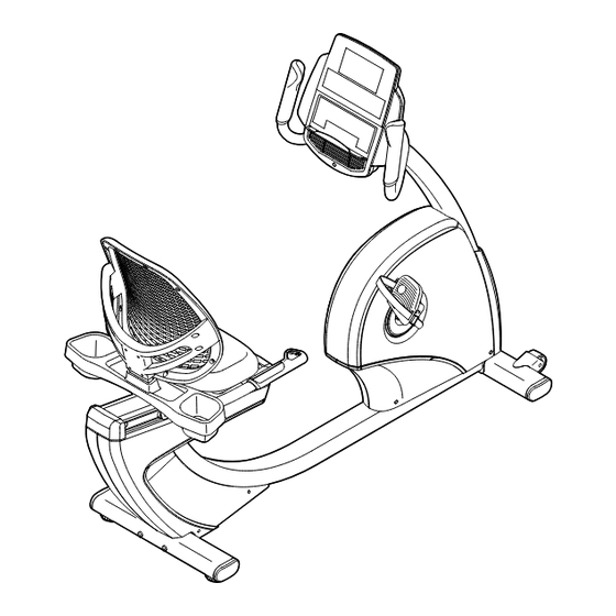
Model No. NTEVEX89915.0
Serial No.
Write the serial number in the
space above for reference.
Serial Number
Decal (under
frame)
CUSTOMER SERVICE
UNITED KINGDOM
Call: 0330 123 1045
From Ireland: 053 92 36102
Website: www.iconsupport.eu
E-mail: csuk@iconeurope.com
Write:
ICON Health & Fitness, Ltd.
Unit 1D, The Gateway
Fryers Way, Silkwood Park
OSSETT
WF5 9TJ
UNITED KINGDOM
AUSTRALIA
Call: 1800 993 770
E-mail: australiacc@iconfitness.com
Write:
ICON Health & Fitness
PO Box 635
WINSTON HILLS NSW 2153
AUSTRALIA
CAUTION
Read all precautions and instruc-
tions in this manual before using
this equipment. Keep this manual
for future reference.
USER'S MANUAL
www.iconeurope.com
Advertisement
Table of Contents

Related Manuals for NordicTrack Elite R110 NTEVEX89915.0


Summary of Contents for NordicTrack Elite R110 NTEVEX89915.0
- Page 1 Model No. NTEVEX89915.0 Serial No. USER’S MANUAL Write the serial number in the space above for reference. Serial Number Decal (under frame) CUSTOMER SERVICE UNITED KINGDOM Call: 0330 123 1045 From Ireland: 053 92 36102 Website: www.iconsupport.eu E-mail: csuk@iconeurope.com Write: ICON Health &...
-
Page 2: Table Of Contents
Apply the decal in the location shown. Note: The decal(s) may not be shown at actual size. NORDICTRACK is a registered trademark of ICON Health & Fitness, Inc. IFIT is a registered trademark of ICON Health & Fitness, Inc. -
Page 3: Important Precautions
IMPORTANT PRECAUTIONS WARNING: To reduce the risk of serious injury, read all important precautions and instructions in this manual and all warnings on your exercise bike before using your exercise bike. ICON assumes no responsibility for personal injury or property damage sustained by or through the use of this product. -
Page 4: Before You Begin
BEFORE YOU BEGIN Thank you for selecting the revolutionary reading this manual, please see the front cover of this NORDICTRACK ELITE R110 exercise bike. Cycling manual. To help us assist you, note the product model ® is an effective exercise for increasing cardiovascular number and serial number before contacting us. -
Page 5: Part Identification Chart
PART IDENTIFICATION CHART Use the drawings below to identify the small parts needed for assembly. The number in parentheses below each drawing is the key number of the part, from the PART LIST near the end of this manual. The number following the key number is the quantity needed for assembly. -
Page 6: Assembly
ASSEMBLY • Assembly requires two persons. • In addition to the included tool(s), assembly requires the following tools: • Place all parts in a cleared area and remove the one Phillips screwdriver packing materials. Do not dispose of the packing materials until you finish all assembly steps. - Page 7 3. Set a sturdy piece of packing material under the front of the Frame (1). Have a second person hold the Frame to prevent it from tipping while you complete this step. Orient the Front Stabilizer (15) as shown. Attach the Front Stabilizer to the Frame (1) with two M10 x 122mm Screws (65).
- Page 8 5. Tip: Avoid pinching the wires. Slide the Upright (2) onto the Frame (1). Attach the Upright (2) with four M10 x 62mm Screws (70); start all the Screws, and then tighten them. Avoid pinching the wires 6. Press the mount on the Front Shield (58) into the Frame (1).
- Page 9 7. Orient the Upright Cover (57) as shown. Hold the Upright Cover near the Upright (2), and insert the wires upward through the Upright Cover. Then, slide the Upright Cover (57) onto the Upright (2). Wire Tie Wires 8. Orient the Handlebar (7) as shown. While a second person holds the Handlebar near the Upright (2), insert the wires upward through the Wire Tie...
- Page 10 10. Tip: Avoid pinching the wires. Attach the Console (4) to the Handlebar (7) with four M4 x 16mm Screws (77); start all the Screws, and then tighten them. Avoid pinching the wires 11. Attach the Upright Cover (57) to the Handlebar (7) with two M4 x 16mm Screws (77).
- Page 11 13. Slide the Accessory Tray (56) onto the Seat Handlebar (10). Attach the Accessory Tray (56) to the Seat Handlebar (10) with four M4 x 16mm Screws (77); start all the Screws, and then tighten them. 14. Orient the Seat (9) as indicated by the sticker. Attach the Seat (9) to the Seat Handlebar (10) with four M6 x 18mm Screws (25) and four M6 Washers (88) (only two of each are shown);...
- Page 12 15. Slide the Backrest Back (81) onto the Seat Handlebar (10). Attach the Backrest Back (81) with four M6 x 30mm Screws (75) and four M6 Washers (88); start all the Screws, and then tighten them. 16. Identify the Right Pedal (21). Using an adjustable wrench, firmly tighten the Right Pedal (21) clockwise into the Right Crank Arm (23).
- Page 13 17. Plug the Power Adapter (51) into the receptacle on the frame of the exercise bike. Note: To plug the Power Adapter (51) into an outlet, see HOW TO PLUG IN THE POWER ADAPTER on page 15. 18. After the exercise bike is assembled, inspect it to make sure that it is assembled correctly and that it functions properly.
-
Page 14: The Chest Heart Rate Monitor
THE CHEST HEART RATE MONITOR HOW TO PUT ON THE HEART RATE MONITOR • Store the heart rate monitor in a warm, dry place. Do not store the heart rate monitor in a plastic bag or If the heart rate monitor looks like the one shown other container that may trap moisture. -
Page 15: How To Use The Exercise Bike
HOW TO USE THE EXERCISE BIKE HOW TO PLUG IN THE POWER ADAPTER HOW TO ADJUST THE PEDAL STRAPS IMPORTANT: If the exercise bike has been exposed To adjust the pedal to cold temperatures, allow it to warm to room straps, first pull the temperature before you plug in the power adapter. - Page 16 CONSOLE DIAGRAM FEATURES OF THE CONSOLE The console also features an iFit mode that enables the console to communicate with your wireless network The advanced console offers an array of features through an optional iFit module. With the iFit mode, designed to make your workouts more effective and you can download personalized workouts, create your enjoyable.
- Page 17 HOW TO USE THE MANUAL MODE Calories per Hour (Calories/Hr)—This display mode will show the approximate number of calories 1. Begin pedaling or press any button on the you are burning per hour. console to turn on the console. Distance (Dist.)—This display mode will show When you turn on the console, the display will turn the distance that you have pedaled in miles or on.
- Page 18 Press the Home button to exit the workout and When your pulse is detected, a heart symbol will return to the default menu (see HOW TO CHANGE flash in the display each time your heart beats, CONSOLE SETTINGS on page 23 to set the one or two dashes will appear, and then your heart rate will be shown.
- Page 19 HOW TO USE AN ONBOARD WORKOUT resistance level and/or target speed is programmed for the next segment, the resistance level and/or 1. Begin pedaling or press any button on the target speed will appear in the display for a few console to turn on the console.
- Page 20 HOW TO USE A SET-A-GOAL WORKOUT Note: The calorie goal is an estimate of the number of calories that you will burn during 1. Begin pedaling or press any button on the the workout. The actual number of calories that console to turn on the console.
- Page 21 HOW TO USE AN IFIT WORKOUT Press the Map button, the Train button, or the Lose Wt. button to download the next workout of that You must have an iFit module to use an iFit workout. type in your schedule. To purchase an iFit module at any time, go to www.iFit.com or call the telephone number on the Press the Compete button to compete in a race...
- Page 22 6. Follow your progress with the display. HOW TO USE THE SOUND SYSTEM See step 4 on page 17. To play music or audio books through the console sound system while you exercise, plug a 3.5 mm male The My Trail tab will show a map of the trail or it will to 3.5 mm male audio cable (not included) into the jack show a track and the number of laps you complete.
- Page 23 HOW TO CHANGE CONSOLE SETTINGS Units—The currently selected unit of measurement will appear in the display. To change the unit of 1. Select the settings mode. measurement, press the Enter button repeatedly. To view distance in miles, select ENGLISH. To view To select the settings mode, press and hold down distance in kilometers, select METRIC.
-
Page 24: Maintenance And Troubleshooting
MAINTENANCE AND TROUBLESHOOTING MAINTENANCE Next, remove the M4 x 16mm Screw (77) from the Access Cover (40). Then, remove the Access Cover. Regular maintenance is important for optimal per- formance and to reduce wear. Inspect and properly Locate the Reed Switch (46). Turn the Left Crank Arm tighten all parts each time the exercise bike is used. - Page 25 HOW TO ADJUST THE DRIVE BELT Next, loosen the M6 x 20mm Hex Screw (84). Tighten the M10 x 50mm Hex Screw (83) until the Drive Belt If the pedals slip while you are pedaling, even while the (47) is tight. When the Drive Belt is tight, tighten the resistance is adjusted to the highest setting, the drive M6 x 20mm Hex Screw.
-
Page 26: Exercise Guidelines
EXERCISE GUIDELINES Burning Fat—To burn fat effectively, you must exer- WARNING: cise at a low intensity level for a sustained period of Before beginning this time. During the first few minutes of exercise, your or any exercise program, consult your physi- body uses carbohydrate calories for energy. - Page 27 SUGGESTED STRETCHES The correct form for several basic stretches is shown at the right. Move slowly as you stretch; never bounce. 1. Toe Touch Stretch Stand with your knees bent slightly and slowly bend forward from your hips. Allow your back and shoulders to relax as you reach down toward your toes as far as possible.
-
Page 28: Part List
PART LIST Model No. NTEVEX89915.0 R0615A Key No. Qty. Description Key No. Qty. Description Frame Reed Switch/Wire Upright Drive Belt Foot Stabilizer Cap Console Left Handlebar Grip Rail Flange Screw Adjustment Bar Power Adapter Handlebar Shield Disc Backrest Heart Rate Monitor Seat Chest Strap Seat Handlebar/Wire... - Page 29 Key No. Qty. Description Key No. Qty. Description M8 Split Washer M6 Small Washer Crank Cap Clip Nut M6 Locknut Power Receptacle/Wire Tree Fastener #6 x 12mm Screw M10 Flange Nut M8 x 28mm Hex Screw M6 Split Washer – Assembly Tool Right Rear Shield –...
-
Page 30: Exploded Drawing
EXPLODED DRAWING A Model No. NTEVEX89915.0 R0615A... - Page 31 EXPLODED DRAWING B Model No. NTEVEX89915.0 R0615A...
-
Page 32: Ordering Replacement Parts
ORDERING REPLACEMENT PARTS To order replacement parts, please see the front cover of this manual. To help us assist you, be prepared to provide the following information when contacting us: • the model number and serial number of the product (see the front cover of this manual) •...
Need help?
Do you have a question about the Elite R110 NTEVEX89915.0 and is the answer not in the manual?
Questions and answers