Table of Contents

Advertisement

TECHNICAL MANUAL
OPERATORS, AVIATION UNIT,
AND AVIATION
I N T E R M E D I A T E M A I N T E N A N C E
F O R
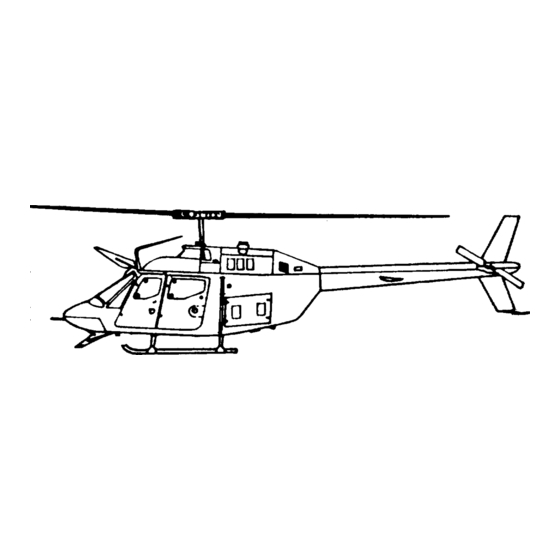
H E L l C O P T E R ,
O B S E R V A T I O N
O H - 5 8 A
&
O H - 5 8 C
ITEM NSN
INSIDE FRONT COVER
This publication supersedes
TM 55-1520-228-BD dated
17 August 1990.
H E A D Q U A R T E R S ,
CHAPTER 1. GENERAL INFORMATION
CHAPTER 2. ASSESSING BATTLEFIELD DAMAGE
CHAPTER 3. GENERAL REPAIR
CHAPTER 4. AIRFRAME
CHAPTER 5. ALIGHTING GEAR
CHAPTER 6. POWER PLANT
CHAPTER 7.
ROTORS
CHAPTER 8. DRIVE TRAIN SYSTEM
CHAPTER 9. HYDRAULIC SYSTEM
CHAPTER 10: INSTRUMENT SYSTEMS
CHAPTER 11. ELECTRICAL SYSTEM
CHAPTER 12. FUEL SYSTEM
CHAPTER 13. FLIGHT CONTROLS
CHAPTER 14. UTILITY SYSTEM
CHAPTER 15. ENVIRONMENTAL CONTROL SYSTEM
CHAPTER 16. MISSION EQUIPMENT
CHAPTER 17. EMERGENCY EQUIPMENT
APPENDIX A . REFERENCES
APPENDIX B. SPECIAL OR FABRICATED TOOLS
APPENDIX C. EXPENDABLE/DURABLE SUPPLIES
APPENDIX D.
SUBSTITUTE MATERIALS/PARTS
APPENDIX E. BDAR TRAINING PROCEDURES
APPENDIX F. AVIONICS CONFIGURATIONS
D E P A R T M E N T
4
J a n u a r y
T M
5 5 - 1 5 2 0 - 2 2 8 - B D
&
O F
T H E
1 9 9 1
MATERIALS
A R M Y

Advertisement

Table of Contents
loading

Summary of Contents for Bell OH-58A

  • Page 1 5 5 - 1 5 2 0 - 2 2 8 - B D TECHNICAL MANUAL OPERATORS, AVIATION UNIT, AND AVIATION I N T E R M E D I A T E M A I N T E N A N C E CHAPTER 1.
  • Page 2 AT THE DISCRETION OF THE COMMANDER AND SHALL BE REPAIRED BY STANDARD MAINTENANCE PROCEDURES AS SOON AS PRACTICABLE AFTER THE MISSION IS COMPLETED. BDAR TECHNIQUES IN THIS MANUAL PERTAIN to the following helicopters: OH-58A Helicopter, Observation NSN 1520-00-169-7137 OH-58C Helicopter, Observation...
  • Page 3 55-1520-228-BD WARNING DATA Personnel performing operations, procedures, and practices which are included or implied in this technical manual shall observe the general following warnings. Disregard of these warnings can cause serious injury or death. WARNINGS FLIGHT SAFETY The standards contained herein allow aircraft to be flown with battle damage substantially in excess of peacetime limits.
  • Page 4 55-1520-228-BD HIGH VOLTAGE is used in this equipment. DEATH ON CONTACT may result if personnel fail to observe safety precautions. Never work on electronic equipment unless there is another person nearby who is familiar with the operation and hazards of the equipment and who is competent in administering first aid.
  • Page 5 TM 55-1520-228-BD E X T E R N A L S T O R E S P r i o r t o a n y h e l i c o p t e r m a i n t e n a n c e f u n c t i o n s t h a t r e q u i r e e x t e r n a l s t o r e s b e r e m o v e d , J E T T I S O N c a r t r i d g e s h a l l b e r e m o v e d .
  • Page 6 TM 55-1520-228-BD LIFTING Lifting or moving heavy equipment incorrectly can cause serious injury. Do not try to lift or move more than 50 pounds by yourself. Bend legs while lifting. D Always use assistants during lifting opera- support heavy weight with your back. Lack of attention or being in tions.
  • Page 7: Blank

    OPERATORS, AVIATION UNIT, AND AVIATION INTERMEDIATE MAINTENANCE BATTLEFIELD DAMAGE ASSESSMENT AND REPAIR FOR HELICOPTER, OBSERVATION OH-58A & OH-58C DISTRIBUTION STATEMENT A: Approved for public release; distribution is unlimited. TM 55-1520-228-BD, dated 4 January 1991, is changed as follows: 1. Remove and insert pages as indicated below. New or changed text material is indicated by a vertical bar in the margin.
  • Page 9 TM 55-1520-228-BD LIST OF EFFECTIVE PAGES Insert latest changed pages. Dispose of superseded pages in accordance with regulations. NOTE: On a changed page, the portion of the text affected by the latest change is indicated by a vertical line, or other change symbol, in the outer margin of the page. Changes to illustrations are indicated by miniature pointing hands.
  • Page 11: Table Of Contents

    OPERATORS, AVIATION UNIT, AND AVIATION INTERMEDIATE MAINTENANCE BATTLEFIELD DAMAGE ASSESSMENT AND REPAIR FOR HELICOPTER, OBSERVATION OH-58A & OH-58C REPORTING ERRORS AND RECOMMENDING IMPROVEMENTS You can help improve this manual. If you find any mistakes, or if you know of a way to improve these procedures, please let us know.
  • Page 12 TM 55-1520-228-BD TABLE OF CONTENTS (Cont) Page CHAPTER 7 - ROTORS Section I. Introduction....Section II. Repairs ....CHAPTER 8 - DRIVE TRAIN SYSTEM Section I.
  • Page 13 TM 55-1520-228-BD TABLE OF CONTENTS (Cont) Page 16-1 CHAPTER 16 - HOIST AND WINCHES....17-1 AUXILIARY POWER PLANT ....CHAPTER 17 - CHAPTER 18 - MISSION EQUIPMENT .
  • Page 14 TM 55-1520-228-BO LIST OF ILLUSTRATIONS (Cont) Title Page Figure Damaged Honeycomb Core Panel, Small Damage to One Skin 4-23 4-64 and Core......4-24 Damaged Honeycomb Core Panel, 2-8 Inch Damage - One Skin 4-64...
  • Page 15 TM 55-1520-228-BD LIST OF ILLUSTRATIONS (Cont) Title Page Figure 9-12 9-13 Assembly of MS Fitting ....9-13 9-14 Union Connection..... . Circuit Identification .
  • Page 16 TM 55-1520-228-BD LIST OF ILLUSTRATIONS (Cont) Page Title Figure 11-47 Preparation of Coax ....11-46 11-49 Installation of Field Expedient Antenna... 11-47 12-2 0H-58 Fuel System.
  • Page 17 Wiring Table, Radar Altimeter AN/APN-209, OH-58C ..F-17 Wiring Table, IFF, APX-72, OH-58A ... . . F-19 Wiring Table, IFF, APX-1OO, OH-58C ... . .
  • Page 18 TM 55-1520-228-BD HOW TO USE THIS MANUAL This manual is developed to assist the soldier in a battlefield environment to make assessment and repair of damage to the OH-58 helicopter which cannot, due to asset availability or environmental factors, be repaired in the normal prescribed manner. Within this technical manual, the word shall is used to indicate a mandatory requirement.
  • Page 19 TM 55-1520-228-BD HOW TO USE THIS MANUAL (Cont) Finding Repairs in this Manual. a. When the damage is obvious and known, find the functional group chapter of Turn to the repair procedure index, section I, which the damaged item is a part. subparagraph c of each chapter to locate the item being repaired.
  • Page 21 TM 55-1520-228-BD CHAPTER 1 GENERAL INFORMATION BDAR FIXES SHALL BE USED ONLY IN COMBAT OR FOR TRAINING AT THE DISCRETION OF THE COMMANDER. (AUTHORIZED TRAINING FIXES ARE LISTED IN APPENDIX E.) IN EITHER CASE, DAMAGES SHALL BE REPAIRED BY STANDARD PROCEDURES AS SOON AS PRACTICABLE.
  • Page 22 TM 55-1520-228-BD GENERAL INFORMATION (6) Fabrication of parts from kits BDAR techniques are not limited to or readily available materials. simple restoration of minimum functional combat capability. If full functional capability can be restored expediently (7) Jury-rigging. with a limited expenditure of time and assets, it will be accomplished.
  • Page 23: Standards And Practices

    TM 55-1520-228-BD GENERAL INFORMATION The ability of a Equipment meets Self-Recovery. e. Combat Capable. battle damaged helicopter to retrieve the minimum functional combat capability itself (fly out) from a battlefield (See paragraph 1-8. ) requirements. It usually will involve environment. f.
  • Page 24 TM 55-1520-228-BD GENERAL INFORMATION 1-7. WAIVER OF PRECAUTIONS. Under (4) Communications. Must have combat conditions, BDAR may be performed intercom communications within aircraft on helicopters which are in flight or and at least two tactical receiver- which are under power while on the transmitter (R-T) units operating at ground.
  • Page 25: Tasks And Responsibilities

    TM 55-1520-228-BD GENERAL INFORMATION outside authorized standard repairs, and WARNING may degrade the inherent safety of the helicopter. Therefore, BDAR actions are Careful consideration shall be given not intended to supplement, replace stan- to the operation of the Identify dard maintenance practices during peace- Friend or FOE (IFF), Mode 4, Failure of the time, nor should they be employed indis-...
  • Page 26 TM 55-1520-228-BD GENERAL INFORMATION (3) If the temporary repair e. Maintenance of Forms. Instruc- tions for the maintenance of forms, requires an inspection at intervals, records, and reports are listed in DA list the required inspection on DA Form PAM 738-751 and TB 55-1500-307-24. When 2408-18.
  • Page 27 55-1520-228-BD GENERAL INFORMATION 3. SERIAL NO. NAME CREW CHIEF/MECHANIC STATlON 1. DATE MODEL 6 PAGE NO. 6a NO. OF PAGES STATUS TODAY AIRCRAFT TIME NEXT INSPECTION STARTS LANDINGS O T H E R INTMED ELEC- ARMA- N0.1 NO. 2 OTHER TIME TO AIRCRAFT TRONIC...
  • Page 28 TM 55-1520-228-BD GENERAL INFORMATION 1. NOMEN CLATURE 2. MODEL 3. SERlAL NUMBER 4. PAGE NO. NO. OF PAGES REEFERENCE ITEM TO BE INSPECTED FREQUENCY NEXT DUE FORM 2404.18. 1 JAN 64 EQUIPMENT INSPECTION LIST For use of this form, see TM 38-750; proponent agency DCSLOG.
  • Page 29 TM 55-1520-228-BD GENERAL INFORMATION MEANINGS MARKINGS TO INDICATE DAMAGE HAS BEEN ASSESSED AND EVALUATED: Draw a circle around the damage. TO INDICATE NO BDAR REPAIR REQUIRED: Write “OK” inside the circle. TO INDICATE STRUCTURAL REPAIRS ARE REQUIRED: Draw a second line about 1/4 to 1/2 way around the initial circle then draw slashes or crosshatch between the two circular lines.
  • Page 30 TM 55-1520-228-BD GENERAL INFORMATION WRITTEN INSTRUCTIONS MEANING See assessor or whoever has signed written instructions See me - print name & for additional information. rank. (Signature) Names of parts to Where compound damage occurs, the names or abbreviations be repaired, (item, of specific items can be written adjacent to the damage skin, stringer.
  • Page 31 TM 55-1520-228-BD GENERAL INFORMATION System identification markings are primarily abbreviations of the system. MARKINGS SYSTEM/MEANING Damage to unknown system. Fuel Fuel Hydraulic High Pressure Low Pressure Elect Electrical Avionics Flt Cont Flight Control Main Rotor Main Rotor Group Tail Rotor Tail Rotor Group Pneumatic Air Cond...
  • Page 33: Chapter 2 - Assessing Battlefield Damage

    TM 55-1520-228-BD CHAPTER 2 ASSESSING BATTLEFIELD DAMAGE BDAR FIXES SHALL BE USED ONLY IN COMBAT OR FOR TRAINING AT THE DISCRETION OF THE COMMANDER. (AUTHORIZED TRAINING FIXES ARE LISTED IN APPENDIX E.) IN EITHER CASE, DAMAGES SHALL BE REPAIRED BY STANDARD PROCEDURES AS SOON AS PRACTICABLE.
  • Page 34 TM 55-1520-228-BD ASSESSING BATTLEFIELD DAMAGE T a b l e 2 - 1 . G e n e r a l D e c i s i o n L o g i c SEE TM 55-1520-328-25...
  • Page 35: General Fault Assessment Table

    TM 55-1520-228-BD ASSESSING BATTLEFIELD DAMAGE to a guide fix in this manual, a stan- General aircraft assessment charts, dard TM 55-1520-228-23 repair if it is Table 2-1, guide you through the air- feasible, or a higher AVIM level of craft’s capability so that all the repair if extent of damage, time con- necessary capabilities are evaluated.
  • Page 36 TM 55-1520-228-BD ASSESSING BATTLEFIELD DAMAGE Table 2-2. General Assessment (Cont)
  • Page 37 TM 55-1520-228-BD ASSESSING BATTLEFIELD DAMAGE Table 2-2. General Assessment (Cont)
  • Page 38 TM 55-1520-228-BD ASSESSING BATTLEFIELD DAMAGE Table 2-2. General Assessment (Cont)
  • Page 39 TM 55-1520-228-BD ASSESSING BATTLEFIELD DAMAGE Table 2-2. General Assessment (Cont)
  • Page 40 55-1520-228-BD ASSESSING BATTLEFIED DAMAGE Table 2-2. General Assessment (Cont) 2 - 8...
  • Page 41 TM 55-1520-228-BD ASSESSING BATTLEFIELD DAMAGE Table 2-2. General Assessment (Cont) 2-9/(2-10 Blank)
  • Page 43: Chapter 3 - General Repairs

    TM 55-1520-228-BD CHAPTER 3 GENERAL REPAIRS BDAR FIXES SHALL BE USED ONLY IN COMBAT OR FOR TRAINING AT THE DISCRETION OF THE COMMANDER. (AUTHORIZED TRAINING FIXES ARE LISTED IN APPENDIX E.) IN EITHER CASE, DANAGES SHALL BE REPAIRED BY STANDARD PROCEDURES AS SOON AS PRACTICABLE.
  • Page 45 TM 55-1520-228-BD CHAPTER 4 AIRFRAME BDAR FIXES SHALL BE USED ONLY IN COMBAT OR FOR TRAINING AT THE DISCRETION OF THE COMMANDER. (AUTHORIZED TRAINING FIXES ARE LISTED IN APPENDIX E.) IN EITHER CASE, DAMAGES SHALL BE REPAIRED BY STANDARD PROCEDURES AS SOON AS PRACTICABLE. Section I.
  • Page 46 TM 55-1520-228-BD AIRFRAME Table 4-1. Aircraft Structure Damage Assessment Prodecures...
  • Page 47 TM 55-1520-228-BD A I R F R A M E Figure 4-1. Aircraft Sections...
  • Page 48 TM 55-1520-228-BD AIRFRAME the damage appears to be (2) Inspect for small and large deferrable; cracks caused by projectile damage. Small cracks will enlarge under con- a detail assessment can be made tinued loading, particularly when and the damage can be repaired by BDAR located at the edge of a hole.
  • Page 49: Chapter 4 - Airframe

    TM 55-1520-228-BD A I R F R A M E Marking and Recording Damage. (3) Inspect all structures using bright light and magnifying glass. (1) Record all detected damage. Determine the path entry of the projec- Refer to Table 4-1 for repair/referral of tile to aid in finding structures that Mark repair on structural member.
  • Page 50 TM 55-1520-228-BD AIRFRAME Figure 4-2. DA Form 2404...
  • Page 51 TM 55-1520-228-BD AIRFRAME CD is the depth of the damage into the (3) Marking damage. Mark the flattened cross section. The length of damaged structure using grease pencil or the remaining effective cross section paint. Use the labeling scheme shown in is still capable of supporting a load.
  • Page 52 TM 55-1520-228-BD AIRFRAME Figure 4-3. Evaluating Damage to Angles, Channels, and Z-Angles...
  • Page 53 TM 55-1520-228-BD AIRFRAME Figure 4-4. Damaged Cross Section...
  • Page 54 TM 55-1520-228-BD AIRFRAME IMPORTANT: MEASURED LATERAL DAMAGE MUST INCLUDE ALL RADIATED CRACKS. Figure 4-5. Measuring Skin Panel Damage 4-10...
  • Page 55 TM 55-1520-228-BD AIRFRAME Figure 4-6. Measuring Damage in Webs and Panels 4-11...
  • Page 56 TM 55-l52O-228-BD AIRFRAME (2) Honeycomb Sandwich Structures. CD' = Allowable depth of damage. Refer to Figure 4-7 for the measurement CL' = Allowable length (width) of of "WL" and "D." If a projectile hits damage. a sandwich panel at an angle, the A' = Allowable area of damage.
  • Page 57 TM 55-1520-228-BD AIRFRAME Figure 4-7. Measuring Damage in Honeycomb Sandwich Panels 4-13...
  • Page 58 TM 55-1520-228-BD AIRFRAME (2) Perform any feasible (1) The factor applies to the on-site BDAR fixes as required for damage actually measured not to the self-recovery. maximum damage limit for the structure. (3) Unload all ammunition, (2) The factor applies to the weapons, stores, and unnecessary equipment.
  • Page 59 TM 55-1520-228-BD AIRFRAME The type, extent, and variation of (b) Repairs on damaged struc- damage under condition 3 does not per- tural elements that are better than mit categorization of the many com- condition 1 may be deferred except for binations of damage.
  • Page 60 TM 55-1520-228-BD AIRFRAME monocoque structure to the four attach- 4-11. GENERAL. ment fittings on the fuselage, is a. The aircraft consists of three accomplished by the use of intercoastals main sections. The forward cabin sec- and two aluminum redistribution bulkheads. The horizontal stabilizer tion extends from the cockpit nose at is a standard spar-rib-skin riveted FS1 to the bulkhead aft of the passenger...
  • Page 61 TM 55-1520-228-BD AIRFRAME Figure 4-8. OH-58 Helicopter 4-17...
  • Page 62 55-1520-228-BD A I R F R A M E PROFILE CENTER TAILROTOR BEARING HANGER. BL - BUTT LINE TANGENCY POINT. FS - FUSELAGE STATION CONTOURS IN BOOM STATIONS ARE CIRCLES. RADIUS AT 31.87 IS 7.3555" WL - WATERLINE RADIUS AT 182.405 IS 3.286". TAPER' OF BOOM IS 0.02703"...
  • Page 63 TM 55-1520-228-BD AIRFRAME Figure 4-10. Cockpit 4-19...
  • Page 64 TM 55-1520-228-BD AIRFRAME Figure 4-11. Fuselage Pylon Support Structure (Sheet 1 of 5) 4-20...
  • Page 65 TM 55-1520-228-BD AIRFRAME Figure 4-11. Fuselage Pylon Support Structure (Sheet 2 of 5) 4-21...
  • Page 66 TM 55-1520-228-BD AIRFRAME Figure 4-11. Fuselage Pylon Support Structure (Sheet 3 of 5) 4-22...
  • Page 67 TM 55-1520-228-BD AIRFRAME FS130 FUSELAGE STA 130 BULKHEAD FS117.71 21.00 Fuselage Pylon Support Structure (Sheet 4 of 5) Figure 4-11. 4-23...
  • Page 68 TM 55-1520-228-BD AIRFRAME Figure 4-11. Fuselage Pylon Support Structure (Sheet 5 of 5) 4-24...
  • Page 69 TM 55-1520-228-BD AIRFRAME Upper and Lower Shell Structure Figure 4-12. 4-25...
  • Page 70 TM 55-1520-228-BD AIRFRAME Figure 4-13. Aft Fuselage Structure 4-26...
  • Page 71 TM 55-1520-228-BD AIRFRAME Figure 4-14. Tail Boom 4-27...
  • Page 72 TM 55-1520-228-BD AIRFRAME Figure 4-15. Cowling and Firewalls 4-28...
  • Page 73 TM 55-1520-228-BD AIRFRAME (4) Three or more fasteners next Determine the priority of the to each other, which join a cap, various required repairs based on repair longeron, and stringer to the web, are time, difficulty of repair, resources sheared, pulled-through or missing. available, tactical situation, and need for the aircraft, etc.
  • Page 74 TM 55-1520-228-BD AIRFRAME oriented so as to produce peeling or Evaluation of Damage to Skin and tearing of the structure in flight. Web Panels. Classify a skin or web panel as failed if any of the following (4) The panel is secured by mecha- conditions exist: nical fasteners.
  • Page 75 55-1520-228-BD AIRFRAME Table 4-2. Dam age Limits Forward Fuselage - Condition I DAMAGE LIMITS ELEMENT CAP/FLANGE SKIN/WEB LOCATION COMPONENT/ CD ' WL ' NOTES/CAUTIONS MEMBER Caps, Stiffeners, (D’=NxCL) (D'=NxWL) 1.00- 20.00- 5.06R- Console, 32.75 44.50 3.06L Doublers 1.05 2.10 10 Forward 1.00- 20.00-...
  • Page 76 Table 4-2. Damage Limits Forwar d Fuselage — C ondition I (Cont) DAMAGE LIMITS LOCATION COMPONENT / NOTES / ELEMENT CAP / FLANGE SKIN / WEB MEMBER CAUTIONS CD’ CL’ WL’ Pedestal Structure 55.14- 20.00- 5.06R- Caps/Stiffeners (D’=N x CL) (D’=N x WL) 73.04 30.17...
  • Page 77 Table 4-2. Damage Limits Forwar d Fuselage — C ondition I (Cont) DAMAGE LIMITS LOCATION COMPONENT / NOTES / ELEMENT CAP / FLANGE SKIN / WEB MEMBER CAUTIONS CD’ CL’ WL’ Passenger Seat 114.79- 31.42- Flanges, Angles, (D’=N x CL) (D’=N x WL) Back Bulkhead 122.20...
  • Page 78 Table 4-2. Damage Limits Forwar d Fuselage — C ondition I (Cont) DAMAGE LIMITS LOCATION COMPONENT / NOTES / ELEMENT CAP / FLANGE SKIN / WEB MEMBER CAUTIONS CD’ CL’ WL’ Aft Cabin 120.00- Gun Mount Channel (D’=N x CL) (D’=N x WL) Enclosure 130.00...
  • Page 79: Damage Limits Forward Fuselage - Condition I

    Table 4-2. Damage Limits Forwar d Fuselage — C ondition I (Cont) DAMAGE LIMITS LOCATION COMPONENT / NOTES / ELEMENT CAP / FLANGE SKIN / WEB MEMBER CAUTIONS CD’ CL’ WL’ Upper Cabin Roof 54.48- Flanges, Formers, (D’=N x CL) (D’=N x WL) Shell 130.00...
  • Page 80 Table 4-3 . Dam age Limits Aft Fuselage — Condition I DAMAGE LIMITS LOCATION COMPONENT / NOTES / ELEMENT CAP / FLANGE SKIN / WEB MEMBER CAUTIONS CD’ CL’ WL’ Upper Longeron 130.00- 72.00- 14.12- Channel (D’=N x CL) (D’=N x WL) 205.00 72.93 4.72L&R...
  • Page 81 Table 4-3 . Dam age Limits Aft Fuselage — Condition I (Cont) DAMAGE LIMITS LOCATION COMPONENT / NOTES / ELEMENT CAP / FLANGE SKIN / WEB MEMBER CAUTIONS CD’ CL’ WL’ Anti-Torque Support 179.92- 58.27- Support and Fittings (D’=N x CL) (D’=N x WL) 181.62 73.37...
  • Page 82: Damage Limits Aft Fuselage - Condition I

    Table 4-3 . Dam age Limits Aft Fuselage — Condition I (Cont) DAMAGE LIMITS LOCATION COMPONENT / NOTES / ELEMENT CAP / FLANGE SKIN / WEB MEMBER CAUTIONS CD’ CL’ WL’ Bulkhead Frame Section (D’=N x CL) (D’=N x WL) 0.40 0.80 205.74...
  • Page 83 NOTES / ELEMENT CAP / FLANGE SKIN / WEB MEMBER CAUTIONS CD’ CL’ WL’ Tail Boom 174.10- Bell Crank Support (D’=N x CL) (D’=N x WL) 182.40 No Damage Allowed 31.87- Driveshaft Support & 182.40 Hangers No Damage Allowed Stabilizer 84.57...
  • Page 84: Damage Limits Forward Fuselage - Condition Ii

    Table 4-5. Damage Limits Forward Fuse lage — Condition II (Cont) DAMAGE LIMITS LOCATION COMPONENT / NOTES / ELEMENT CAP / FLANGE SKIN / WEB MEMBER CAUTIONS CD’ CL’ WL’ Honeycomb 44.00- 21.00- 5.06R- Panel Edges (D’=N x CL) (D’=N x WL) Panel 57.10 32.50...
  • Page 85 Table 4-5. Damage Limits Forward Fuse lage — Condition II (Cont ) DAMAGE LIMITS LOCATION COMPONENT / NOTES / ELEMENT CAP / FLANGE SKIN / WEB MEMBER CAUTIONS CD’ CL’ WL’ Center Post 73.00- 24.48- 3.00L Side Webs and (D’=N x CL) (D’=N x WL) 87.85 72.00...
  • Page 86 Table 4-5. Damage Limits Forward Fuse lage — Condition II (Cont) DAMAGE LIMITS LOCATION COMPONENT / NOTES / ELEMENT CAP / FLANGE SKIN / WEB MEMBER CAUTIONS CD’ CL’ WL’ Bulkhead FS130, 51.72- Inboard, Outboard (D’=N x CL) (D’=N x WL) Upper 72.00 Frames, Webs...
  • Page 87 Table 4-5. Damage Limits Forward Fuse lage — Condition II (Cont) DAMAGE LIMITS LOCATION COMPONENT / CAP / FLANGE SKIN / WEB ELEMENT NOTES / CAUTIONS MEMBER CD’ CL’ WL’ Cabin Roof Beam 67.92- 3.00L- Bulkhead Skin and (D’=N x CL) (D’=N x WL) 71.96 3.00R...
  • Page 88 Table 4-5. Damage Limits Forward Fuse lage — Condition II (Cont) DAMAGE LIMITS LOCATION COMPONENT / NOTES / ELEMENT CAP / FLANGE SKIN / WEB MEMBER CAUTIONS CD’ CL’ WL’ Landing Gear 73.00& 18.30& 13.30L&R Attachment Fasteners (D’=N x CL) (D’=N x WL) and Inserts 130.00...
  • Page 89: Damage Limits Aft Fuselage - Condition Ii

    Table 4-6. Damage Limits Aft Fuse lage — Condition II (Cont) DAMAGE LIMITS LOCATION COMPONENT / NOTES / ELEMENT CAP / FLANGE SKIN / WEB MEMBER CAUTIONS CD’ CL’ WL’ Aft Fuselage 130.00- Longeron Stiffeners (D’=N x CL) (D’=N x WL) 206.25 Upward 0.75...
  • Page 90 Table 4-6. Damage Limits Aft Fuse lage — Condition II (Cont) DAMAGE LIMITS LOCATION COMPONENT / NOTES / ELEMENT CAP / FLANGE SKIN / WEB MEMBER CAUTIONS CD’ CL’ WL’ Shear Web 192.84- 7.00- Stiffeners (D’=N x CL) (D’=N x WL) 206.35 4.00L&R 0.40...
  • Page 91: Damage Limits Tail Boom And Landing Gear - Condition Ii

    2.10 182.40 174.10- Fin Supports 0.50 1.00 182.40 174.10- Gearbox Mounting No Damage Allowed 182.40 Plate 174.10- Bell Crank Support No Damage Allowed 182.40 31.87- Driveshaft Support No Damage Allowed 182.40 and Hangers Stabilizer 84.57 Spar 1.50 3.00 Honeycomb Panels 4.50...
  • Page 92 TM 55-1520-228-BD AIRFRAME (1) The firewall shows sign of (5) There are large holes or severe overstress such as buckling and cracks in an area of the door or hatch exposed to the windstream, and peeling misalignment. or tearing of the material in flight is probable.
  • Page 93: Expedient Structural Repairs

    TM 55-1520-228-BD AIRFRAME classify the structure as failed even if (a) Structural movement which the physical damage is within allowable might change the location or alignment limits. Controls and drive- of a component. shafts will be particularly critical. 4-14. BDAR REPAIR PROCEDURE INDEX. (b) Structural damage which PARA.
  • Page 94: Metal Substitution Chart

    55-1520-228-BD Table 4-8. Metal Substitution Chart A I R F R A M E 4-50...
  • Page 95 TM 55-1520-228-BD AIRFRAME Special Repair Techniques. One NOTE method to create a complex curve in a Steel and aluminum are incom- normally straight angle or T - Profile patible materials and normally member is to place appropriate cuts and stop drill holes to allow bends, as require special precautions.
  • Page 96 TM 55-1520-228-BD AIRFRAME Figure 4-16. Typical Former Repair (Sheet 1 of 2) 4-52...
  • Page 97 TM 55-1520-228-BD AIRFRAME Typical Former Repair (Sheet 2 of 2) Figure 4-16. 4-53...
  • Page 98 TM 55-1520-228-BD AIRFRAME Figure 4-17. Cutout in Damaged Skin Cut a piece of substitute stringer NOTE or stiffener to extend a minimum of six fasteners beyond the damage on each end. Stiffener can be placed on out- Use an angle, channel, or z-angle extru- side;...
  • Page 99 TM 55-1520-228-BD AIRFRAME Figure 4-18. Patch Plate PERSONNEL/TIME REQUIRED: PROCEDURAL STEPS: 2 Soldiers 2 Hours Smooth off ragged edges on damaged skin. MATERIALS/TOOLS REQUIRED: Patch Plate Tape over hole. Use several Cherry Rivets (item 38, Appx C) layers as necessary, and overlap onto skin well beyond damaged area.
  • Page 100 TM 55-1520-228-BD AIRFRAME Figure 4-19. Typical Patch Plate Repair 4-56...
  • Page 101 TM 55-1520-228-BD AIRFRAME Install a minimum of six rivets in PROCEDURAL STEPS: each row on each damaged end of major structure such as caps, extrusions, etc. Remove sections of the aircraft skin Remove existing rivets and back drill containing the damage. Do not cut cap holes in the patch plate if the area is or longeron, but cut off ragged ends,...
  • Page 102 TM 55-1520-228-BD AIRFRAME Figure 4-20. Expedient Cap/Longeron Repair 4-58...
  • Page 103 TM 55-1520-228-BD AIRFRAME the repair strap will overlap on the damaged 4-19. FRAME, BULKHEAD, SKIN, AND STRINGER DAMAGE. bulkhead flange and stringer, remove rivets and back drill if the area is accessible. If back drilling is not feasible, interpitch new rivets between GENERAL INFORMATION: A damaged flange existing rivets.
  • Page 104 TM 55-1520-228-BD AIRFRAME Figure 4-21. Repair of Damaged Bulkhead Flange 4-60...
  • Page 105 TM 55-1520-228-BD AIRFRAME Typical Combination Repair (Sheet 1 of 2) Figure 4-22. 4-61...
  • Page 106 TM 55-1520-228-BD AIRFRAME Figure 4-22. Typical Combination Repair (Sheet 2 of 2) 4-62...
  • Page 107: And Core

    TM 55-1520-228-BD AIRFRAME Record BDAR action taken. When Remove existing rivets where the mission is complete, as soon as repair parts will overlap existing practical, repair the equipment/system rivets if the area is accessible for using standard maintenance procedures. back-drilling holes. If not, install rivets between existing rivets if space permits.
  • Page 108: Damaged Honeycomb Core Panel, Small Damage To One Skin And Core

    TM 55-1520-228-BD AIRFRAME 2“ MAX Figure 4-23. Damaged Honeycomb Core Panel, Small Damage to One Skin and Core Figure 4-24. Damaged Honeycomb Core Panel, 2-8 Inch Damage - One Skin and Core MAKE PATCH FROM 2024-T3 OR 7075-T6 ALCLAD ALUMINUM 1/8”...
  • Page 109: Skins And Core

    TM 55-1520-228-BD AIRFRAME MATERIALS/TOOLS REQUIRED: PERSONNEL/TIME REQUIRED: 1 Soldier . 2 Patch Plates Cherry Rivets . 2 Hours MATERIALS/TOOLS REQUIRED: PROCEDURAL STEPS: . Drill with No. 30 Bit Router Remove damaged skin and core, Figure Metal Set (item 2, Appx C) or 4-28.
  • Page 110 TM 55-1520-228-BD AIRFRAME Damage Repair, Accessible One Side Only Figure 4-26. Patch Plates, One Side Accessible Repair Figure 4-27. 4-66...
  • Page 111 TM 55-1520-228-BD AIRFRAME Figure 4-28. Repair of Honeycomb Core Panel, 8 Inches - Both Skins and Core Damage Over 4-67...
  • Page 112 TM 55-1520-228-BD AIRFRAME Drill small holes 1/2 to 3/4 inch PROCEDURAL STEPS: spacing, 3/8 inch edge distance along Remove protruding sections of both sides of any crack and along the sides of the hole. damaged skins and core. Clean area with solvent.
  • Page 113 TM 55-1520-228-BD AIRFRAME Fracture Lacing With Safety Wire Figure 4-29. 4-69...
  • Page 114: Tail Boom Skin Damage

    TM 55-1520-228-BD AIRFRAME Prepare a patch of 2024-T3 aluminum LIMITATIONS: None - Condition 1. 0.050 thick and shape to contour of tail Inspect after every flight for The patch must extend a minimum of boom. damage growth. 3 inches forward and aft, and 1 inch above and below the damaged area, Figure 4-30.
  • Page 115: Chapter 5 - Alighting Gear

    TM 55-1520-228-BD CHAPTER 5 ALIGHTING GEAR BDAR FIXES SHALL BE USED ONLY IN COMBAT OR FOR TRAINING AT THE DISCRETION OF THE COMMANDER. (AUTHORIZED TRAINING FIXES ARE LISTED IN APPENDIX E.) IN EITHER CASE, DAMAGES SHALL BE REPAIRED BY STANDARD PROCEDURES AS SOON AS PRACTICABLE.
  • Page 116: Landing Gear And Support Installation

    TM 55-1520-228-BD ALIGHTING GEAR Figure 5-1. Landing Gear and Support Installation Figure 5-2. Skid Tube Damage Zones...
  • Page 117: Assessment Procedure Logic

    TM 55-1520-228-BD ALIGHTING GEAR Table 5-1. Assessment Procedure Logic...
  • Page 118: Skid Damage

    TM 55-1520-228-BD ALIGHTING GEAR If alighting gear supporting Visually inspect structures sup- structure is damaged but still func- porting alighting gear attachment points tional and the transmission supporting and transmission attachment points for structure shows no damage, release for any signs of structural distress such as flight.
  • Page 119: Skid Repair

    TM 55-1520-228-BD ALIGHTING GEAR Skid Repair Figure 5-3. Clamp Repair Figure 5-4.
  • Page 120: Fabricated Clamp

    TM 55-1520-228-BD ALIGHTING GEAR Figure 5-5. Fabricated Clamp...
  • Page 121: Introduction

    Table 6-1, refers to BDAR repair proce- 6-1. DESCRIPTION, POWER PLANT. The dures which have been developed. power plant consists of a T63-A-700 on the OH-58A and a T63-A-720 on the OH-58C 6-3. REPAIR PROCEDURE INDEX. mounted between FS120.O and FS206.0, Engine connections are Figure 6-1.
  • Page 122: T63 Series Engine

    TM 55-1520-228-BD POWER PLANT Figure 6-1. T63 Series Engine...
  • Page 123: Engine Bdar Assessment Logic

    POWER PLANT Table 6-1. Engine BDAR Assessment Logic...
  • Page 124 TM 55-1520-228-BD POWER PLANT a. When increasing fuel to the LIMITATIONS: Revised engine start engine, grasp the throttle firmly with procedure. both hands and accelerate engine slowly. Monitor TOT and N1 gauges for possible stall readings. Blocking of the air bleed valve will render the engine highly susceptible to surge which could NOTE...
  • Page 125: Blocking Plate Installation

    TM 55-1520-228-BD POWER PLANT Figure 6-2. Blocking Plate Installation NOTE 6-6. DOUBLE-CHECK VALVE INOPERATIVE. Should any of the three components GENERAL INFORMATION: The double-check valve, along with both accumulators, is sustain damage or otherwise be rendered inoperable, the remaining situated in-line between the power tur- bine governor and the fuel control, and functional items should be recon- nected.
  • Page 126 TM 55-1520-228-BD POWER PLANT PERSONNEL/TIME REQUIRED: MATERIALS/TOOLS REQUIRED: . 1 Soldier . Flex Line Tubing (ID 0.25 in., . 15 Minutes Length 12 in. min) . No. 4 Fittings MATERIALS/TOOLS REQUIRED: . Flex Line Tubing (ID 0.25 in., PROCEDURAL STEPS: Length 12 in.
  • Page 127 TM 55-1520-228-BD POWER PLANT Double-Check Valve System, Possible Alternatives Figure 6-3.
  • Page 128: Wood Plug

    TM 55-1520-228-BD POWER PLANT PROCEDURAL STEPS: MATERIALS/TOOLS REQUIRED: . Tape, Fiberglass or Duct Obtain a small piece of hose or (item 51, Appx C) tubing and insert the piece into the . Solvent, Naptha (item 7, Appx C) hole on the oil tank, Figure 6-4. or Equivalent Insert a tapered wooden plug inside PROCEDURAL STEPS:...
  • Page 129: Sealant For Small Holes

    TM 55-1520-228-BD POWER PLANT Replenish oil supply. Record BDAR action taken. When mission is complete, as soon as practical, repair the equipment/system using standard maintenance procedures Figure 6-5. Sealant for Small Holes OPTION 4: Screw, Washer, and Gasket (for small holes) Repair Using Screw, Figure 6-6.
  • Page 130: Hose Assembly, Sealant, Nut, And Bolt

    TM 55-1520-228-BD POWER PLANT Use a piece of hose/tubing about the If oil tank plate was removed, same diameter of the hole. Assemble reinstall. bolt, hose/tubing, washer, and nut, Figure 6-7. Apply sealant to all After sealant has dried, replenish edges.
  • Page 131 TM 55-1520-228-BD POWER PLANT If sealant is to be used, clean area OPTION 6: Sheet Metal with Sealant around hole with solvent so sealant will and/or Blind Rivets (for large holes). stick. PERSONNEL/TIME REQUIRED: 3. Put sealant or gasket material over .
  • Page 132 TM 55-1520-228-BD POWER PLANT Figure 6-8. Sheet Metal Plate with Sealant and/or Cherry Rivets 6-12...
  • Page 133 TM 55-1520-228-BD CHAPTER 7 ROTORS BDAR FIXES SHALL BE USED ONLY IN COMBAT OR FOR TRAINING AT THE DISCRETION OF THE COMMANDER. (AUTHORIZED TRAINING FIXES ARE LISTED IN APPENDIX E.) IN EITHER CASE, DAMAGES SHALL BE REPAIRED BY STANDARD PROCEDURES AS SOON AS PRACTICABLE. Section 1.
  • Page 134: Main Rotor System

    TM 55-1520-228-BD ROTORS 10. Blade Latch 1. Pitch Link 11. Blade Assy 2. Lever 12. Retaining Bolt 3. Idler Link 4. Swashplate Assy 13. Grip 14. Mast Nut 5. Link 6. Collective Lever 15. Hub Assy (Oil Lubricated shown) 7. Inner Ring 16.
  • Page 135 TM 55-1520-228-BD ROTORS 1. Hub 2. Pitch Horn 3. Blade 4. Tail Rotor Gearbox Tail Rotor System Figure 7-2.
  • Page 136: Assessment Procedures

    TM 55-1520-228-BD ROTORS Table 7-1. Assessment Procedures...
  • Page 137 TM 55-1520-228-BD ROTORS Rotor Blades, Damage Sensitive Areas Figure 7-3.
  • Page 138 TM 55-1520-228-BD ROTORS MATERIALS/TOOLS REQUIRED: 2. Smooth damage; remove all rough . Army Green Tape, Maximum Width edges. Available; 3 Inches Minimum or Aluminized Tape (item 50, Appx C) Clean area around damage and . Fiberglass or Aluminum Wafers completely around blade where tape is .
  • Page 140 TM 55-1520-228-BD ROTORS 8. Wrap a layer of tape around the Record BDAR action taken. When entire blade and over the repaired area. mission is complete, as soon as practical, repair the equipment/system using standard maintenance procedures. 9. Wrap exact number of tape wraps on opposite side at approximately same span location.
  • Page 141 TM 55-1520-228-BD CHAPTER 8 DRIVE TRAIN SYSTEM BDAR FIXES SHALL BE USED ONLY IN COMBAT OR FOR TRAINING AT THE DISCRETION OF THE COMMANDER. (AUTHORIZED TRAINING FIXES ARE LISTED IN APPENDIX E.) IN EITHER CASE, DAMAGES SHALL BE REPAIRED BY STANDARD PROCEDURES AS SOON AS PRACTICABLE.
  • Page 142 TM 55-1520-228-BD DRIVE TRAIN SYSTEM 10. Disc Assy Mast 11. Bearing Hangar and Support Transmission Assy Bracket Main Driveshaft 12. Hangar (Blower Assy) Freewheeling Assy 13. Oil Cooler Forward Short Tail Rotor 14. Coupling (Main Driveshaft) Driveshaft 15. Splined Adapter Oil Cooling Blower and 16.
  • Page 143 TM 55-1520-228-BD DRIVE TRAIN SYSTEM Figure 8-1. Drive Train System (Sheet...
  • Page 145 TM 55-1520-228-BD DRIVE TRAIN SYSTEM Drive Train System (Sheet 4 of 4) Figure 8-1.
  • Page 146: Drive Train System (Sheet 1 Of 4)

    TM 55-1520-228-BD DRIVE TRAIN SYSTEM Table 8-1. Drive Train System BDAR Assessment Procedures...
  • Page 147 TM 55-1520-228-BD DRIVE TRAIN SYSTEM LIMITATIONS: None. c. Tape should extend beyond damaged area 1 to 2 inches in either direction. PERSONNEL/TIME REQUIRED: . 1 Soldier Record BDAR action taken. When . 20 Minutes mission is complete, as soon as practical, repair the equipment/system MATERIALS/TOOLS REQUIRED: using standard maintenance procedures.
  • Page 148: External Components - Transmission Oil System

    TM 55-1520-228-BD DRIVE TRAIN SYSTEM Filler Cap 9. Oil Filter Oil Cooler 10. Oil Filter Head Assy Transfer Tube 11. Filter Bypass Valve Nozzle (Jet) 12. Oil Temperature Switch Pressure Regulating Valve 13. Oil Pump Hoses and Lines 14. Chip Detector Oil Pressure Transmitter 15.
  • Page 149 TM 55-1520-228-BD DRIVE TRAIN SYSTEM Figure 8-3. Flex Duct Repair (Sheet 1 of 2)
  • Page 150 TM 55-1520-228-BD DRIVE TRAIN SYSTEM Flex Duct Repair (Sheet 2 of 2) Figure 8-3. 8-10...
  • Page 151 TM 55-1520-228-BD DRIVE TRAIN SYSTEM Install plug and packing where Install plug and packing where switch (8) was previously installed. transmitter (7) was previously installed. Secure loose electrical connector Secure loose electrical connector and cable with tie wraps. and cable with tie wraps. Check for leaks.
  • Page 152 TM 55-1520-228-BD DRIVE TRAIN SYSTEM Small oil loss can be LIMITATIONS: PROCEDURAL STEPS: tolerated. If aircraft is run for an extended period of time with little or Clean damaged area with solvent. no oil, gearbox will jam. Close bullet hole with a plug and hold in place with tape.
  • Page 153 TM 55-1520-228-BD CHAPTER 9 HYDRAULIC BDAR FIXES SHALL BE USED ONLY IN COMBAT OR FOR TRAINING AT THE DISCRETION OF THE COMMANDER. (AUTHORIZED TRAINING FIXES ARE LISTED IN APPENDIX E.) IN EITHER CASE, DAMAGES SHALL BE REPAIRED BY STANDARD PROCEDURES AS SOON AS PRACTICABLE. Section I.
  • Page 154: Hydraulic System

    TM 55-1520-228-BD HYDRAULIC Hose (Pressure) 1. Quick Disconnect (Pressure) Hose (Pressure 2. Quick Disconnect (Return) Hose (Pressure) 3. Filter (Return) Hose (Return] 4. Filter (Pressure) pressure Switch 5. Vent Line Relief Valve 6. Reservoir To Servo Actuator (Collective) 7. Tachometer Generator To Servo Actuator (Cycilc) 8.
  • Page 155 TM 55-1520-228-BD HYDRAULIC Filter Bypass Valve 1. Reservoir Relief Valve 2. Baffle Solenoid Valve 3. Scupper Drain Pressure Switch 4. Quick Disconnects 11. Servo Actuator, Cyclic 5. Pump Servo Actuator, 6. Check Valve Collective 7. Filter F i g u r e 9 - 2 .
  • Page 156: Assessment Logic

    TM 55-1520-228-BD HYDRAULIC Logic Table 9-1. Assessment Figure 9-3. Two-Part Fitting...
  • Page 157: Four-Part Fitting

    TM 55-1520-228-BD HYDRAULIC Figure 9-4. Four-Part Fitting Figure 9-5. Using Tube Cutter 9 - 5...
  • Page 158 TM 55-1520-228-BD HYDRAULIC In Line Repair. Ratchet the cutter around the tubing OPTION 1: applying a light pressure to the cutting wheel by intermittently twisting the LIMITATIONS: None. setscrew. Too much pressure on the cutting wheel could deform the tubing or PERSONNEL/TIME REQUIRED: Soldier cause excessive burring.
  • Page 159: Properly Burred Tubing

    TM 55-1520-228-BD HYDRAULIC SECTION A-A Properly Burred Tubing Figure 9-6. Damaged Tube Section Figure 9-7.
  • Page 160: Splice Repair Assembly

    TM 55-1520-228-BD HYDRAULIC Figure 9-8. Splice Repair Assembly Figure 9-9. Repair Fitting and Tube Installation...
  • Page 161 TM 55-1520-228-BD HYDRAULIC Substitute with High Pressure 9-8. HYDRAULIC HOSE DAMAGE. OPTION 2: Hose (damage to section of tubing with GENERAL INFORMATION: The hydraulic bends). hoses on the OH-58 are braided wire covered rubber hose. Repair of damage PERSONNEL/TIME REQUIRED: or wear to the wire braids is deferrable 1 Soldier for one more flight, provided the rubber...
  • Page 162: Damaged Tube Section-Complex Bends

    TM 55-1520-228-BD HYDRAULIC Figure 9-10. Damaged Tube Section-Complex Bends Figure 9-11. Splice Adapter Assembly Installation 9-10...
  • Page 163 TM 55-1520-228-BD HYDRAULIC Insert the MS sleeve between the Record BDAR action taken. When wire braid cover and the inner rubber mission is complete, as soon as hose. Force onto hose until the edge of practical, repair the equipment/system the sleeve is even with the end of the using standard maintenance procedures.
  • Page 164: Installation Of Socket And Sleeve

    TM 55-1520-228-BD Figure 9-12. Installation of Socket and Sleeve Figure 9-13. Assembly of MS Fitting 9-12...
  • Page 165: Union Connection

    TM 55-1520-228-BD HYDRAULIC Figure 9-14. Union Connection Section III. SEALS, PACKINGS, AND GASKETS 9-9. O-RING, PACKING, AND GASKET (3) Seal replacement is required when: APPLICATIONS. a. O-rings are used in static and (a) The amount of fluid being dynamic applications. lost will cause system failure.
  • Page 166 TM 55-1520-228-BD HYDRAULIC Selection of Proper Packing or 9-10. HYDRAULIC FLUID SUBSTITUTIONS. Selection of proper packing or Gasket. a. If the original specified fluid is gasket for a particular application is lost and standard replacement is not of the utmost importance. The exact available, a substitute fluid must be size, shape, and material composition...
  • Page 167: Seals Reference And Temperature Guides Chart

    Table 9-2. Seals Reference and Temperature Guides Chart MILITARY PARKER BASE TEMP GUIDE DURO- SERIES COMPOUND POLYMER CONT SERV SPECIFICATION METER SERVICE Air Force and Navy hydraulic fluid AN6227B MIL-P-5516 NITRILE MIL-H-5606, AN67230B Class B PS-01-30-5 (BUNA N) -65°F to +180°F MIL-H-83282 NITRILE (BUNA N)
  • Page 168 Seals Reference and Temperature Guides Chart (Cont) Table 9-2. PARKER BASE TEMP GUIDE DURO- SERVICE AND DESIGNATION CONT SERV METER COMPOUND POLYMER SPECIFICATIONS ASTMID735-58T SERIES Mineral oil & hy- draulic fluid, water, steam, coolants, NITRILE SB620 B E1 -40°F to +250°F (BUNA N) pneumatic service.
  • Page 169 Seals Reference and Temperature Guides Chart (Cont) Table 9-2. TEMP GUIDE DURO- SERVICE AND PARKER BASE DESIGNATION METER POLYMER CONT SERV SPECIFICATIONS SERIES ASTMID735-58T COMPOUND Water service. Low swell, extremely stable. Oil NITRILE SB71O B E1 -40°F to +250°F resistance. (BUNA N) E3 F1 N398-7...
  • Page 171 TM 55-1520-228-BD CHAPTER 10 INSTRUMENTS BDAR FIXES SHALL BE USED ONLY IN COMBAT OR FOR TRAINING AT THE DISCRETION OF THE COMMANDER. (AUTHORIZED TRAINING FIXES ARE LISTED IN APPENDIX E.) IN EITHER CASE, DAMAGES SHALL BE REPAIRED BY STANDARD PROCEDURES AS SOON AS PRACTICABLE. There are no BDAR repairs offered for the instrument systems.
  • Page 173: Circuit Identification

    TM 55-1520-228-BD CHAPTER 11 ELECTRICAL AND AVIONICS SYSTEM BDAR FIXES SHALL BE USED ONLY IN COMBAT OR FOR TRAINING AT THE DISCRETION OF THE COMMANDER. (AUTHORIZED TRAINING FIXES ARE LISTED IN APPENDIX E.) IN EITHER CASE, DAMAGES SHALL BE REPAIRED BY STANDARD PROCEDURES AS SOON AS PRACTICABLE.
  • Page 174: Electrical And Avionics Assessment Logic

    TM 55-1520-228-BD ELECTRICAL AND AVIONICS SYSTEM Table 11-1. Electrical and Avionics Assessment Logic Figure 11-1. Circuit Identification 11-2...
  • Page 175: Function And Designation Letters

    TM 55-1520-228-BD ELECTRICAL AND AVIONICS SYSTEM Table 11-2. Function and Designation Letters CIRCUIT CIRCUIT DESIGNATION DESIGNATION LETTER CIRCUITS LETTER CIRCUITS ARMAMENT: FLIGHT INSTRUMENT: Bomb suspension & release Bank and turn Guns Rate of climb Chemical Directional gyro Rocket Air position Sight Ground position Turret...
  • Page 176 TM 55-1520-228-BD ELECTRICAL AND AVIONICS SYSTEM Function and Designation Letters (Cont) Table 11-2. CIRCUIT CIRCUIT DESIGNATION DESIGNATION LETTER CIRCUITS LETTER CIRCUITS FUEL AND OIL: ENGINE CONTROL: Fuel valves Blower ratio Fuel booster-pump motor Starter Moisture control Warning Oil dilution Engine primer LIGHTING: Fuel-transfer-pump motor...
  • Page 177 TM 55-1520-228-BD ELECTRICAL AND AVIONICS SYSTEM Table 11-2. Function and Designation Letters (Cont) CIRCUIT CIRCUIT DESIGNATION DESIGNATION LETTER CIRCUITS LETTER CIRCUITS MISCELLANEOUS ELECTRONIC: RADAR: Electronic wiring for which no SA-Altimeter SF-Intercept "R", "S", or "T" designation has been assigned by the procuring SG-Gunlaying activity shall have the circuit SM-Mapping...
  • Page 178 TM 55-1520-228-BD ELECTRICAL AND AVIONICS SYSTEM 11-3. REPAIR PROCEDURE INDEX. PARA. PARA. Coax Splice for RG-9 B/U, Splicing Unshielded Wires. . . 11-5 RG-214/U, RG-225/U, and Wire Repair Segments, Unshielded Wires ..11-6 RG-393/U ..11-17 Damaged Wire Insulation .
  • Page 179: Unshielded Crimp Splice Application

    TM 55-1520-228-BD ELECTRICAL AND AVIONICS SYSTEM A temporary repair returns the CAUTION electrical wiring system to a reduced Make sure aircraft power is off. level of capacity with a possible slight reduction of system operational capabi- Disconnect battery before touching any wires. lity.
  • Page 180 TM 55-1520-228-BD ELECTRICAL AND AVIONICS SYSTEM Figure 11-2. Crimp Splice 11-8...
  • Page 181 TM 55-1520-228-BD ELECTRICAL AND AVIONICS SYSTEM Shrink sealing sleeve over crimp OPTION 3: Split Bolt Splice Connectors. Use reflector, tem- with heat gun. perature set at 900°F. LIMITATIONS: Only to be used on wire sizes AWG No. 4 through No. 10. Inspect Record BDAR action taken.
  • Page 182: Splicing With Terminal Lug Barrel

    TM 55-1520-228-BD ELECTRICAL AND AVIONICS SYSTEM Figure 11-3. Splicing with Terminal Lug Barrel MATERIALS/TOOLS REQUIRED: Heat the tape to shrink it onto the Tape, Electrical (item 46, Appx C) splice and soften the adhesive layer. Strippers or Knife Use reflector (located in A29 of wiring kit), temperature set at 900°F.
  • Page 183 TM 55-1520-228-BD ELECTRICAL AND AVIONICS SYSTEM Twist Wire Repair Figure 11-4. MATERIALS/TOOLS REQUIRED: Cover splice area with electrical Cylindrical metal casing such as ball tape. point pen refills, expended cartridges, etc. If a section of wire needs to be Insulation Sleeve or Tape replaced, a double repair can be made, (item 10, Appx B) Figure 11-5.
  • Page 184 TM 55-1520-228-BD ELECTRICAL AND AVIONICS SYSTEM Figure 11-5. Replacement Section; Twist Wire Repair Figure 11-6. Metal Casing Splice Repair 11-12...
  • Page 185 TM 55-1520-228-BD ELECTRICAL AND AVIONICS SYSTEM Insulate with tape or use plastic Slide the insulating sleeve over the and string. Tie in place. splice so that the ends of the insu- lating sleeve extend at least 3/4 of an inch beyond the ends of each terminal Record BDAR action taken.
  • Page 186: Bolted Terminal Lug Repair Of Large Wires

    TM 55-1520-228-BD ELECTRICAL AND AVIONICS SYSTEM Figure 11-7. Bolted Terminal Lug Repair of Large Wires Figure 11-8. Replacement Section; Terminal Lug Repair 6. Ram or push the two wire ends together so that the strands interlink. Secure with screw clamp, control cable clamp, safety wire, or other suitable means, Figure 11-9.
  • Page 187 TM 55-1520-228-BD ELECTRICAL AND AVIONICS SYSTEM DAMAGED WIRE INSULATION. 11-7. 11-6. WIRE REPAIR SEGMENTS, UNSHIELDED WIRES. GENERAL INFORMATION: If the wire insu- lation is damaged but the wire itself is GENERAL INFORMATION. The BDAR electri- not, repair of the insulation may be cal wiring kit has wire replacement accomplished by installing heat-shrink- segments for replacement sections up to...
  • Page 188: Heat-Shrinkable Tape

    TM 55-1520-228-BD ELECTRICAL AND AVIONICS SYSTEM Heat the tape to shrink it and melt PROCEDURAL STEPS: the adhesive layer. Use reflector (A29), temperature set at 900°F. Remove damaged insulation and examine to insure center conductor is Record BDAR action taken. When not damaged.
  • Page 189: Shielded Cable Repair Preparation

    TM 55-1520-228-BD ELECTRICAL AND AVIONICS SYSTEM PROCEDURAL STEPS: 11-8. SHIELDED CABLE REPAIR. Remove damaged insulation and GENERAL INFORMATION: The following pro- examine to insure center conductor is cedures may be used to repair severed not damaged. shielded cables. Wrap tape over exposed center con- Shielded Cable Splice.
  • Page 190: Shielded Cable Splice Preparation

    TM 55-1520-228-BD ELECTRICAL AND AVIONICS SYSTEM Figure 11-13. Shielded Cable Splice Preparation Center and shrink the shield over Table 11-5. Shielded Cable Repair the splice area so that the solder melts and flows. Shield sleeve braid must overlap cable braid at both ends. Refer to Figure 11-14.
  • Page 191: Shielded Cable Spliced

    TM 55-1520-228-BD ELECTRICAL AND AVIONICS SYSTEM Figure 11-14. Shielded Cable Spliced If an insulating sleeve is used, PROCEDURAL STEPS: slide into place and tie both ends Select a grounding sheath. Figure 11-15, step d. If heat shrink is used, slide into place and shrink into Prepare the severed ends of the position.
  • Page 192 TM 55-1520-228-BD ELECTRICAL AND AVIONICS SYSTEM Figure 11-15. Shielded Cable Repair 11-20...
  • Page 193: Shielded Cable Repair

    TM 55-1520-228-BD ELECTRICAL AND AVIONICS SYSTEM Shielding must be long enough to overlap PROCEDURAL STEPS: the shielding on both sides of the cable Prepare severed ends of cable for being repaired after the center conduc- pigtail method of shield terminations, tor is repaired.
  • Page 194 TM 55-1520-228-BD ELECTRICAL AND AVIONICS SYSTEM PIGTAILS STEP A STEP B Figure 11-16. Pigtail Method Repair 11-22...
  • Page 195 TM 55-1520-228-BD ELECTRICAL AND AVIONICS SYSTEM Substitute Shielded Braid Repair Figure 11-17. 11-23...
  • Page 196: Shield Terminator Repair Preparation

    TM 55-1520-228-BD ELECTRICAL AND AVIONICS SYSTEM MATERIALS/TOOLS REQUIRED: Replacement Segment (item 10, Appx B) Stripper or Knife Splice (item 10, Appx B) Insulation Sleeve (item 10, Appx B) Crimp Tool PROCEDURAL STEPS: Cut out damaged cable (up to 9 inches in length). Prepare cable for splice.
  • Page 197: Shield Terminator Repair

    TM 55-1520-228-BD ELECTRICAL AND AVIONICS SYSTEM Position ground lead and shield ter- minator as shown in Figure 11-21. Heat shield terminator until solder ring melts; then, continue heating for an additional 15 seconds or until sleeve WINDOW STRIP starts to turn brown. Use reflector with temperature set at 900°F.
  • Page 198 TM 55-1520-228-BD ELECTRICAL AND AVIONICS SYSTEM 11-12. TERMINAL BOARDS. MATERIALS/TOOLS REQUIRED: Strippers or Knife Replacement Terminal Lug (Table GENERAL INFORMATION: The terminal boards provided are all 5 inches in 11-6) length. They are located in the wiring Crimp Tool (item 10, Appx B) kit.
  • Page 199: Self-Clinching Cable Strap

    TM 55-1520-228-BD ELECTRICAL AND AVIONICS SYSTEM Self-Clinching Cable Straps. OPTION 1: WIRE STRIP LIMITATIONS: These straps are not to be S T U D used under the following conditions: LENGTH WIRE (IN) S I Z E SIZE ITEM In temperature environments which M7928/1-7 exceed 85°C (185°F).
  • Page 200 TM 55-1520-228-BD ELECTRICAL AND AVIONICS SYSTEM Thread tip through eye then hand pull strap tight against the bundle. Refer to Figure 11-23. Adjust the tool tension setting to 7. Pass the free end of the cable tie through the slot in the end of the tool then push tool snugly against the strap, Figure 11-24.
  • Page 201: Tie Tape Repair Procedure

    TM 55-1520-228-BD ELECTRICAL AND AVIONICS SYSTEM CAUTION Do not tighten wire or string too much, as wire or string can cut into or deform insulation. Space ties at 12 inches or less. Record BDAR action taken. When mission is complete, as soon as practical, repair the equipment/system using standard maintenance procedures.
  • Page 202 TM 55-1520-228-BD ELECTRICAL AND AVIONICS SYSTEM Slide the shield sleeve and inner Slide shield sleeve, inner sleeve, and filler sleeve onto one of the sleeve onto one of the coaxial cables coaxial cables in the given order. in the order given. Splice the center conductor.
  • Page 203: Coax Splice Inner Sleeve

    TM 55-1520-228-BD ELECTRICAL AND AVIONICS SYSTEM Figure 11-27. Coax Splice Inner Sleeve Figure 11-28. Coax Splice Shield Sleeve PROCEDURAL STEPS: Record BDAR action taken. When mission is complete, as soon as Prepare coax cable, Figure 11-26. practical, repair the equipment/system Refer to Table 11-5.
  • Page 204: Coax Splice With Cable Braid Over Barrier Sleeves

    TM 55-1520-228-BD ELECTRICAL AND AVIONICS SYSTEM MATERIALS/TOOLS REQUIRED: Coax Splice (item 10, Appx B) Stripper or Knife Reflector (item 10, Appx B) Heat Gun (item 10, Appx B) PROCEDURAL STEPS: Prepare coax cable, Figure 11-26. Figure 11-31. Coax Repair with Cable Refer to Table 11-5.
  • Page 205: Component Bypass

    TM 55-1520-228-BD ELECTRICAL AND AVIONICS SYSTEM Record BDAR action taken. When mission is complete, as soon as practical, repair the equipment/system using standard maintenance procedures. Figure 11-32. Component Bypass CONNECTOR REPAIR. 11-20. GENERAL INFORMATION: Deformed, crushed, missing, or otherwise damaged connectors can be replaced or repaired.
  • Page 206: Damaged Connector And Pigtail

    TM 55-1520-228-BD ELECTRICAL AND AVIONICS SYSTEM PROCEDURAL STEPS: Record BDAR action taken. When mission is complete, as soon as Obtain a replacement connector with practical, repair the equipment/system a pigtail. (Replacement may be obtained using standard maintenance procedures. from a crash damaged aircraft.) Cut pigtail so that splices can be staggered, OPTION 3: Cannibalizing Connector from...
  • Page 207: Circuit Breakers

    TM 55-1520-228-BD ELECTRICAL AND AVIONICS SYSTEM Connect back of circuit breaker to 11-21. CIRCUIT PROTECTION DEVICE REPAIR. line and bus bar by reinstalling the two phillips screws. GENERAL INFORMATION: Attempt to main- tain a fused system at all times. Circuits with damage circuit breakers Place inside star washer and nut on can be repaired by: front of circuit breaker and tighten...
  • Page 208 TM 55-1520-228-BD ELECTRICAL AND AVIONICS SYSTEM Figure 11-35. Circuit Breakers 11-36...
  • Page 209: Construction Of Fuse Link

    TM 55-1520-228-BD ELECTRICAL AND AVIONICS SYSTEM No. 38 AWG strands of wire. Insert the other end of No. 38 AWG strands of wire into the other terminal lug (supply side). Pull tight against the piece of insulation and twist tight. Insulate bare end of terminal lugs on both sides of 1 inch piece of insulation with tape.
  • Page 210 TM 55-1520-228-BD ELECTRICAL AND AVIONICS SYSTEM Same repair procedure can be used to 11-22. BUS BARS. lengthen bus bars, Figure 11-39. GENERAL INFORMATION: Rigid bus bars are Record BDAR action taken. When used in the power distribution circuits mission is complete, as soon as of the aircraft.
  • Page 211: Splicing Bus Bars

    TM 55-1520-228-BD ELECTRICAL AND AVIONICS SYSTEM Figure 11-38. Splicing Bus Bars Figure 11-39. Lengthening Bus Bars 11-39...
  • Page 212: Battery, Storage Bb-476/A, Cell Layout

    TM 55-1520-228-BD ELECTRICAL AND AVIONICS SYSTEM Some loss of battery 5. After removing bad cells, prepare LIMITATIONS: voltage (1.25 to 1.50 V dc per cell jumper from 1 foot of No. 4 AWG and two terminal lugs. removed) and amperage capacity. Remove 1/2 inch of insu- lation from one end of wire and crimp terminal lug on stripped end of wire.
  • Page 213: Block Diagram Power Relay, Check And Test

    TM 55-1520-228-BD ELECTRICAL AND AVIONICS SYSTEM damage to the control circuit wiring. 11-24. DAMAGED OR DEFECTIVE POWER RELAYS. Repair control circuit wiring. With 24-28 V dc applied to terminals X1 or GENERAL INFORMATION: A power relay is X2 of the power relay, check the voltage an electrically operated switch between between terminals A1, A2, and the the main bus and other electrical com-...
  • Page 214 TM 55-1520-228-BD ELECTRICAL AND AVIONICS SYSTEM LIMITATIONS: Emergency repair. No LIMITATIONS: None. control over jumpered power relays, circuit cannot be turned on or off. PERSONNEL/TIME REQUIRED: . 1 Soldier . 30 Minutes PERSONNEL/TIME REQUIRED: . 1 Soldier . 20 Minutes MATERIALS/TOOLS REQUIRED: .
  • Page 215 TM 55-1520-228-BD ELECTRICAL AND AVIONICS SYSTEM DRAWING PART DESIGNATION NUMBER FUNCTION MS24183D1 Relay, BATTERY MS24183D1 Relay, External Pwr 3S2791G200F-9 Relay, Gen Fail MS24183D1 Relay, Line Cont MS24183D1 Relay, Non-Ess Bus BB-4761A Battery Figure 11-42. Location of Power Relays 11-43...
  • Page 216: Block Diagram, Typical Power Relays

    TM 55-1520-228-BD ELECTRICAL AND AVIONICS SYSTEM TYPE B TYPE A Block Diagram, Typical Power Relays Figure 11-43. Figure 11-44. Jumper Wire Fabrication Record BDAR action taken. When WARNING mission is complete, as soon as Do not touch bare wires on expe- practical, repair the equipment/system dient antennas with the radio using standard maintenance procedures.
  • Page 217 TM 55-1520-228-BD ELECTRICAL AND AVIONICS SYSTEM MATERIALS/TOOLS REQUIRED: None To replace No. 1 FM radio, be sure that FM 1 circuit breaker and BAT switches on the overhead console are PROCEDURAL STEPS: off. Be sure that FM No. 1 (1 AN/ARC-114) circuit breaker and BAT switches on the Slide the No.
  • Page 218: Frequency Vs. Wave Length

    TM 55-1520-228-BD ELECTRICAL AND AVIONICS SYSTEM Frequency Wavelength FM radio with frequency range of 30 to 69.95 MHZ. Center of frequency range is 50 MHZ. Using Figure 11-45, look under frequency column for 50 MHZ on the wave length side of the Table, 6 M is shown. Use Figure 11-45 to convert meters to feet.
  • Page 219: Preparation Of Coax

    TM 55-1520-228-BD ELECTRICAL AND AVIONICS SYSTEM Figure 11-45. Preparation of Coax 11-47...
  • Page 220 TM 55-1520-228-BD ELECTRICAL AND AVIONICS SYSTEM Twist the center conductor from the tail boom. Replace the structural panel radiating element of the antenna to the and secure with screws. center conductor of the coax. Make a good mechanical joint and insulate with NOTE tape.
  • Page 221: Installation Of Field Expedient Antenna

    TM 55-1520-228-BD ELECTRICAL AND AVIONICS SYSTEM Installation of Field Expedient Antenna Figure 11-47. 11-49/(11-50 Blank)
  • Page 223 TM 55-1520-228-BD CHAPTER 12 FUEL SYSTEM BDAR FIXES SHALL BE USED ONLY IN COMBAT OR FOR TRAINING AT THE DISCRETION OF THE COMMANDER. (AUTHORIZED TRAINING FIXES ARE LISTED IN APPENDIX E.) IN EITHER CASE, DAMAGES SHALL BE REPAIRED BY STANDARD PROCEDURES AS SOON AS PRACTICABLE.
  • Page 224 TM 55-1520-228-BD FUEL SYSTEMS RECEIVER 1. Cover Assembly 2. Low Level Switch 3. Lower Transmitter 4. Fuel Pump 5. Fuel Shut-Off Valve 6. Fuel Shut-Off Cable NOTE 7. Fuel Shut-Off Lever 8. Auxiliary Fuel RECEIVER REPLACES CAP AND ADAPTER ON HELICOPTERS Cell Fitting EQUIPPED WITH CLOSED CIRCUIT REFUELING PROVISIONS.
  • Page 225: Fuel System Assessment Procedures

    TM 55-1520-228-BD FUEL SYSTEMS Fuel System Assessment Procedures Table 12-1. 12-3...
  • Page 226 TM 55-1520-228-BD FUEL SYSTEMS Section III. FUEL CELL DAMAGE 12-7. FUEL CELL DAMAGE. PROCEDURAL STEPS: Defuel the fuel cell by the GENERAL INFORMATION: The fuel cells restrict the catastrophic loss of fuel following procedure: in survivable crashes. The repairs spe- cified in this section, however, will a.
  • Page 227 TM 55-1520-228-BD FUEL SYSTEMS Emergency Mechanical Clamp Repair Figure 12-2. 12-5...
  • Page 228 TM 55-1520-228-BD FUEL SYSTEMS Refuel the aircraft. CAUTION Record BDAR action taken. When Wear goggles or other eye protec- mission is complete, as soon as tion during all operations. practical, repair the equipment/system using standard maintenance procedures. a. Remove the tape band from Semkit cartridge and pull the mixing rod straight up toward the top of the OPTION 2: Adhesive Repair.
  • Page 229: Mixing Instruction For Sealant Cartridges

    TM 55-1520-228-BD FUEL SYSTEMS Mixing Instruction for Sealant Cartridges Figure 12-3. Record BDAR action taken. When . Apply adhesive to the wound opening mission is complete, as soon as for a least 1-1/2 inches around the practical, repair the equipment/system damaged area or enough to accept the using standard maintenance procedures.
  • Page 230 TM 55-1520-228-BD FUEL SYSTEMS Pull the plug into position and Once step 1 of this section has been completed, locate the damage; enlarge the rotate it in position to smooth out the wound in the tank to no more than 3 adhesive interface.
  • Page 231: Rubber Repair Plug Assembly

    TM 55-1520-228-BD FUEL SYSTEMS Figure 12-4. Rubber Repair Plug Assembly Plug Modification for Three Plane Repair Figure 12-5. 12-9/(12-10 Blank)
  • Page 233 (1) Copilot to Pilot. If any be uncontrollable and forced to crash land. control rods, bell-cranks, or linkages connecting the copilot controls to the pilot controls break or otherwise become 13-5. TUBES, FLIGHT CONTROL. inoperable, the pilot may assume full...
  • Page 234 TM 55-1520-228-BD Figure 13-1. OH-58 Flight Controls Schematic FLIGHT CONTROLS SYSTEM 13-2...
  • Page 235: Flight Control System Assessment Procedures

    TM 55-1520-228-BD FLIGHT CONTROLS SYSTEM Flight Control System Assessment Procedures Table 13-1. 13-3...
  • Page 236 TM 55-1520-228-BD FLIGHT CONTROLS SYSTEM copilot’s and pilot’s cyclic, collec- Reinstall tube after repair is accomplished, and check for binding or tive, and tail rotor controls to the aft interference by manually moving the flight control components. See Figure appropriate controls: cyclic, collec- 13-1 for a schematic of the system, and tive, or pedals.
  • Page 237: Collective Flight Control

    TM 55-1520-228-BD FLIGHT CONTROLS SYSTEM Figure 13-2. Collective Flight Control 13-5...
  • Page 238: Cyclic Flight Control

    TM 55-1520-228-BD FLIGHT CONTROLS SYSTEM Figure 13-3. Cyclic Flight Control 13-6...
  • Page 239: Flight Control Actuators

    TM 55-1520-228-BD FLIGHT CONTROLS SYSTEM 13-7 Figure 13-4. Flight Control Actuators...
  • Page 240: Anti-Torque Controls (Sheet 1 Of 2)

    TM 55-1520-228-BD FLIGHT CONTROLS SYSTEM NOTE THIS IS A CONFIGURATION OF THE OH-58A SERIES HELlCOPTER. 13-8 Figure 13-5. Anti-Torque Controls (Sheet 1 of 2)
  • Page 241 TM 55-1520-228-BD FLIGHT CONTROLS SYSTEM NOTE THIS IS A CONFIGURATION OF THE OH-58C SERIES HELlCOPTER. Figure 13-5. Anti-Torque Controls (Sheet 2 of 2) 13-9...
  • Page 242: Control Tube Dimensions

    TM 55-1520-228-BD FLIGHT CONTROLS SYSTEM (Refer to Figures 13-2 thru 13-5) Figure 13-6. Control Tube Dimensions Figure 13-7. Suggested Repair for Control Rods or Tubes 13-10...
  • Page 243: Nominal Tube Splice Sizes

    TM 55-1520-228-BD FLIGHT CONTROLS SYSTEM Table 13-2. Nominal Tube Splice Sizes SIZE PART LENGTH (IN) I.D. NUMBER O.D. WALL 13-2 1680-00-125-8871 206-001-174-3 15/16 .065 13-2 3040-01-010-6779 206-001-096-7 1 3/8 41.9 13-3 3040-00-179-6880 206-001-306-11 1 15/16 .049 19.7 25.2 13-3 3040-01-012-5969 206-001-096-1 1 3/8 46.1...
  • Page 244: Control Rod With Bearing And Clevis Assemblies

    TM 55-1520-228-BD FLIGHT CONTROLS SYSTEM Figure 13-8. Control Rod with Bearing and Clevis Assemblies 13-12...
  • Page 245: Flattened End Of Fabricated Flight Control

    TM 55-1520-228-BD FLIGHT CONTROLS SYSTEM Flattened End of Fabricated Flight Control Figure 13-9. Figure 13-10. Corner Rounding on Fabricated Flight Control Figure 13-11. Bearing Assembly Connection of Fabricated Flight Control 13-13...
  • Page 246 TM 55-1520-228-BD FLIGHT CONTROLS SYSTEM From Table 13-2, determine the Record BDAR action taken. When correct distance between holes of the mission is complete, as soon as flight tube. Mark this distance. Drill practical, repair the equipment/system the hole and install the bolt. using standard maintenance procedures.
  • Page 247 TM 55-1520-228-BD CHAPTER 14 UTILITY SYSTEM BDAR FIXES SHALL BE USED ONLY IN COMBAT OR FOR TRAINING AT THE DISCRETION OF THE COMMANDER. (AUTHORIZED TRAINING FIXES ARE LISTED IN APPENDIX E.) IN EITHER CASE, DAMAGES SHALL BE REPAIRED BY STANDARD PROCEDURES AS SOON AS PRACTICABLE.
  • Page 248 TM 55-1520-228-BD UTILITY SYSTEMS Figure 14-1. Engine De-Ice System 14-2...
  • Page 249 (CO) indicator located at the instrument panel in full view of bleed air, and defogging systems. the pilot. OH-58A/C has one of three types of heat systems: bleed air, Figures 15-1 thru 15-3; combustion heater, Figure 15-4; WARNING or shroud heater system, Figure 15-5.
  • Page 250 TM 55-1520-228-BD ENVIRONMENTAL CONTROL SYSTEM Figure 15-1. Bleed Air Heating and Ventilating System A & C 15-2...
  • Page 251 TM 55-1520-228-BD ENVIRONMENTAL CONTROL SYSTEM Windshield Defog Nozzle Vent and Defog Control Plenum Drain Heat Control Plenum Valve Assembly Heat Control Cable Ventilating and Defogging Blower Bleed Air Tube Ram Air Intake Grill Mixing Valve Air Distribution Vents Plenum Coupling Remote Sensor Clamp Fresh Air Inlet...
  • Page 252 TM 55-1520-228-BD ENVIRONMENTAL CONTROL SYSTEM 1. Vent Control Plenum Drain 2. Heat Control Plenum Valve Assembly 3. Heat Control Cable Ventilating and Defogging Blower 4. Bleed Air Tube Ram Air Intake Grill 5. Mixing Valve Air Distribution Valves 6. Plenum Cargo/Passenger Area 7.
  • Page 253: Combustion Heater

    TM 55-1520-228-BD ENVIRONMENTAL CONTROL SYSTEM Combustion Heater Plenum Fuel Shut-Off Valve Fuel Pump Fuel Pressure Relief Valve Fuel Filter Heater Combustion Blower Air Scoop Igniter Plug Duct Firewall Shut-Off Control Temperature Control Pilot Seat Back Copilot Seat Back Combustion Heater Figure 15-4.
  • Page 254: Shroud Heater System Schematic

    TM 55-1520-228-BD ENVIRONMENTAL CONTROL SYSTEM Defogger Distribution Valves Blower Cockpit Distribution Valves Air Mixing Valve Cabin Distribution Valves Firewall Shut-Off Valve Fan Air Intake Air Mixing Valve Control Cold Air Intake Firewall Shut-Off Valve Shroud Assembly Control Figure 15-5. Shroud Heater System Schematic 15-6...
  • Page 255: Assessment Procedures

    TM 55-1520-228-BD ENVIRONMENTAL CONTROL SYSTEM Table 15-1. Assessment Procedures 15-7...
  • Page 256 TM 55-1520-228-BD ENVIRONMENTAL CONTROL SYSTEM Stop drill any cracks which might be PROCEDURAL STEPS: extending from hole. Locate damaged area and remove panels and/or other items as necessary Sand both the bottom surface of the patch and the surface area around the to gain access to the duct to be hole to be covered by the patch.
  • Page 257 TM 55-1520-228-BD ENVIRONMENTAL CONTROL SYSTEM Wrap glass tape several turns around 3. Record BDAR action taken. When Tape should mission is completed or as soon as duct to cover hole or tear. feasible, replace duct using standard extend beyond damaged area 3 to 4 inches maintenance procedures.
  • Page 258 TM 55-1520-228-BD ENVIRONMENTAL CONTROL SYSTEM Figure 15-6. Bleed Air Line Installation 15-10...
  • Page 259: Bleed Line Patch Repair

    TM 55-1520-228-BD ENVIRONMENTAL CONTROL SYSTEM Bleed Line Patch Repair Figure 15-7. 15-11/(15-12 Blank)
  • Page 261 TM 55-1520-228-BD CHAPTER 16 MISSION EQUIPMENT BDAR FIXES SHALL BE USED ONLY IN COMBAT OR FOR TRAINING AT THE DISCRETION OF THE COMMANDER. (AUTHORIZED TRAINING FIXES ARE LISTED IN APPENDIX E.) IN EITHER CASE, DAMAGES SHALL BE REPAIRED BY STANDARD PROCEDURES AS SOON AS PRACTICABLE.
  • Page 263 TM 55-1520-228-BD CHAPTER 17 EMERGENCY EQUIPMENT BDAR FIXES SHALL BE USED ONLY IN COMBAT OR FOR TRAINING AT THE DISCRETION OF THE COMMANDER. (AUTHORIZED TRAINING FIXES ARE LISTED IN APPENDIX E.) IN EITHER CASE, DAMAGES SHALL BE REPAIRED BY STANDARD PROCEDURES AS SOON AS PRACTICABLE.
  • Page 265: A-2 Blank

    TM 55-1500-328-25 ..Policies and Procedures TM 55-1520-228-10 ..Operator's Manual Army Model OH-58A/C Helicopter TM 55-1520-228-1,2 ..Aviation Unit and Intermediate Maintenance Manual TM 55-1520-228-CL .
  • Page 267 TM 55-1520-228-BD APPENDIX B SPECIAL OR FABRICATED TOOLS BDAR FIXES SHALL BE USED ONLY IN COMBAT OR FOR TRAINING AT THE DISCRETION OF THE COMMANDER. (AUTHORIZED TRAINING FIXES ARE LISTED IN APPENDIX E.) IN EITHER CASE, DAMAGES SHALL BE REPAIRED BY STANDARD PROCEDURES AS SOON AS PRACTICABLE.
  • Page 268 TM 55-1520-228-BD APPENDIX B SPECIAL OR FABRICATED TOOLS ITEM DESCRIPTION Composite Structures Repair Kit Not Assigned Connector Repair Kit (Special Tools 5935-01-161-5883 for Electrical Connector Repair) (11851) DMC658 4920-01-266-7535 Emergency Repair Kit (Special and Common Tools for Electrical Repair, (11851) DMC895 including Repair Parts) Fluid Line Repair Kit (Special and 4920-01-266-7534...
  • Page 269 TM 55-1520-228-BD APPENDIX C EXPENDABLE/DURABLE SUPPLIES AND MATERIALS LIST BDAR FIXES SHALL BE USED ONLY IN COMBAT OR FOR TRAINING AT THE DISCRETION OF THE COMMANDER. (AUTHORIZED TRAINING FIXES ARE LISTED IN APPENDIX E.) IN EITHER CASE, DAMAGES SHALL BE REPAIRED BY STANDARD PROCEDURES AS SOON AS PRACTICABLE.
  • Page 270 TM 55-1520-228-60 APPENDIX C APPENDIX C Section II. EXPENDABLE SUPPLIES AND MATERIALS LIST ITEM UNIT OF DESCRIPTION ISSUE NUMBER 5330-00-192-5051 Abrasive Cloth (Grit 180) P-C-451 Adhesive, ENA934 NA B/A 8040-00-932-1945 Type II, Class 3 (81348) Adhesive, Epoxy Metal Set A4 8040-00-944-7292 (33564) EA9340 8030-00-723-4599...
  • Page 271 TM 55-1520-228-BD APPENDIX C APPENDIX C Section II. EXPENDABLE SUPPLIES AND MATERIALS LIST (Cont) ITEM UNIT OF NUMBER DESCRIPTION ISSUE 9505-00-596-5101 Lockwire, Steel 0.020 (81348) QQ-W-423 9505-00-293-4208 Lockwire, Steel 0.032 (81348) QQ-W-423 9505-00-331-3275 Lockwire, Steel 0.041 (81348) QQ-W-423 9150-00-186-6681 Lubricating Oil MIL-L-2104 (Grade 30) (15958) 9150-00-180-6266 Lubricating Oil, MIL-L-23699...
  • Page 272 TM 55-1520-228-BD APPENDIX C APPENDIX C Section II. EXPENDABLE SUPPLIES AND MATERIALS LIST (Cont) ITEM UNIT OF DESCRIPTION ISSUE NUMBER Terminal, Lug Crimp Style Stud, 5940-00-283-5380 Size 6, Wire Gage 16-14 Terminal, Lug, Crimp Style Stud, 5940-00-143-4780 Size 10, Wire Gage 16-14 Terminal, Lug (81349) MIL-T-7928 5940-00-143-4777 Terminal, Quick Disconnect...
  • Page 273: Essential Spare Parts

    TM 55-1520-228-BD APPENDIX D SUBSTITUTE MATERIALS/PARTS BDAR FIXES SHALL BE USED ONLY IN COMBAT OR FOR TRAINING AT THE DISCRETION OF THE COMMANDER. (AUTHORIZED TRAINING FIXES ARE LISTED IN APPENDIX E.) IN EITHER CASE, DAMAGES SHALL BE REPAIRED BY STANDARD PROCEDURES AS SOON AS PRACTICABLE.
  • Page 274 TM 55-1520-228-BD APPENDIX D APPENDIX D Table D-1. Essential Spare Parts NATIONAL STOCK ITEM DESCRIPTION NUMBER Actuator, Electro-Mech 2995-00-134-4543 • • • Ammunition Gage Block Ammunition Chute 7.62 1005-06-938-8226 6140-00-228-8447 Battery, Storage 5306-00-616-6472 Bolt Bolt, NAD 1304-8 5306-00-655-7443 Bolt 5306-00-616-6471 Bolt 5306-00-806-7697 Bolt...
  • Page 275 TM 55-1520-228-BD APPENDIX D Table D-2. Spare and Repair Parts NOUN/NSN PUMP SUBMERGED 2915-01-124-5222 LINEAR ACTUATOR 2995-00-134-4543 FORCE GRADIENT CYL. 1680-00-126-4350 IGNITER EXCITER 2925-00-444-1186 PRESSURE ALTIMETER 6610-00-179-5254 ATTITUDE INDICATOR 6610-00-150-6583 COURSE INDICATOR 5826-00-505-3094 PRESSURE ALTIMETER 6610-00-179-5242 VERTICAL SPEED IND. 6610-00-935-4278 VOLTMETER INDICATOR 6625-00-003-8745 PRESSURE ALTIMETER...
  • Page 276 55-1520-228-BD APPENDIX D Table D-2. Spare and Repair Parts (Cont) NOUN/NSN MOUNT 5895-00-935-9582 UHF RADIO SET 5821-00-138-7990 COMPENSATOR 6605-00-487-4773 DIRECTIONAL GYRO 6615-00-167-9757 COMPASS TRANSMITTER 6605-00-531-2992 AN/ARC-114 5821-00-935-5071 RADIO SET AN/ARC-115 5821-00-935-5072 INVERTER 5841-01-140-0941 ELECTRICAL INDICATOR 6620-01-065-3740 HOT AIR MIXING VALVE 4810-01-089-4105 INDICATOR,GAS PRODUCER...
  • Page 277: Weapons

    TM 55-1520-228-BD APPENDIX D Table D-2. Spare and Repair Parts (Cont) T a b l e D - 3 . W e a p o n s NOTE 2: All subcomponents of the major components may be removed and substituted; however, the level of disassembly must be consistent wlth the field tools and skill levels available.
  • Page 278 TM 55-1520-228-BD APPENDIX D Section II. FUELS c. When using substitute fuels, it is SCOPE. This section explains the B-3. preferable to premix the fuels in a use of substitute fuels to be used on container for better blending before the OH-58 helicopter.
  • Page 279 TM 55-1520-228-BD APPENDIX D Table D-4. Substitute Fuel Fuels for JP-4 MILITARY COMMERCIAL EXPEDIENT SPECIFI- SPECIFI- PRIMARY FUEL ALTERNATE FUEL FUEL CATION CATION Aviation Tur- bine: MIL-T- 5624(JP4) NATO-F-40 MIL-T-5624(JP-5) NATO-F-44 Aviation Turbine: ASTM-D-1655 (Jet B) Aviation Turbine: MIL-T-83133 (JP-8) NATO-F-34 Aviation Turbine: ASTM-D-1655 (Jet A-1)
  • Page 280: Fuels For The Oh-58 Helicopter

    TM 55-1520-228-BD APPENDIX D Table D-5. Fuels for The OH-58 Helicopter Alternate Fuels Source Primary or Standard Fuel U.S. Military Fuel JP-4(MIL-T-5624) JP-5(MIL-T-5624) JP-8(MIL-T-83133) NATO Code No. FOREIGN FUEL NATO F-40 NATO-44 NATO-34 TURBINE FUEL, TURBINE FUEL, TURBINE FUEL, A V I A T I O N : AVIATION: AVIATION TYPE: PRODUCT...
  • Page 281: Substitute Commercial Fuels

    TM 55-1520-228-BD APPENDIX D Table D-6. Substitute Commercial Fuels SOURCE PRIMARY OR STANDARD FUEL ALTERNATE FUELS JP-8(MIL-T-83133) U.S. MILITARY FUEL JP-4(MIL-T-5624) JP-5(MIL-T-2624) F-44 NATO CODE NO. F-40 F-34 COMMERCIAL FUEL JET A JET B JET A-1 (ASTM-D-1655) American JP-4 American Type A American Oil Co.
  • Page 282: Alternate And Expedient Fuel Blends

    TM 55-1520-228-BD APPENDIX D Table D-7. Alternate and Expedient Fuel Blends BASE FUEL EXTENDER (50% MAXIMUM) NOTE Fuel may be extended on an alternate basis with the following blends up to a half and half mixture. Any Alternate Fuel Any Primary Fuel Any Alternate Fuel Any Primary Fuel MIL-F-815 Distillate...
  • Page 283: D-12 Blank

    TM 55-1520-228-BD APPENDIX D Section III. LUBRICANTS AND HYDRAULIC FLUIDS (2) They may allow an increase in D-6. SCOPE. This section lists pri- mary, alternate, and expedient lubri- wear because of improper viscosity. cants and hydraulic fluids. (3) They may cause seals to swell or create deposits because of improper D-7.
  • Page 285: Shielded Cable Repair

    TM 55-1520-244-BD APPENDIX E BDAR FIXES AUTHORIZED FOR TRAINING BDAR FIXES SHALL BE USED ONLY IN COMBAT OR FOR TRAINING AT THE DISCRETION OF THE COMMANDER. (AUTHORIZED TRAINING FIXES ARE LISTED IN APPENDIX E.) IN EITHER CASE, DAMAGES SHALL BE REPAIRED BY STANDARD PROCEDURES AS SOON AS PRACTICABLE.
  • Page 286 TM 55-1520-228-BD APPENDIX E BDAR FIXES AUTHORIZED FOR TRAINING (Cont) PARA NO. REPAIR PROCEDURE FLIGHT CONTROL SYSTEM 13-4 Tubes, Flight Control ....ENVIRONMENTAL CONTROL SYSTEM 15-5 Rigid Plastic Ventilation Duct .
  • Page 287 TM 55-1520-228-BD APPENDIX F AVIONICS CONFIGURATIONS BDAR FIXES SHALL BE USED ONLY IN COMBAT OR FOR TRAINING AT THE DISCRETION OF THE COMMANDER. (AUTHORIZED TRAINING FIXES ARE LISTED IN APPENDIX E.) IN EITHER CASE, DAMAGES SHALL BE REPAIRED BY STANDARD PROCEDURES AS SOON AS PRACTICABLE.
  • Page 288 TM 55-1520-228-BD APPENDIX F Figure F-1. Intercom System (Sheet 1 of 2)
  • Page 289 TM 55-1520-228-BD APPENDIX F DRAWING PART DESIGNATION NUMBER FUNCTION TJ11E-02-01 Module, Terminal Junction 1021-DOO1 Audio Threshold U92AU Jack, Telephone JF13E01-02 Frame, Electronic U94A/U Plug, Connector U92AU Jack, Telephone C-6533/ARC Control, Intercom C-6533/ARC Control, Intercom C-6533/ARC Control, Intercom MS25039-1 Switch, Push JF13E01-04 Rack, Electronic 206-075-483-1...
  • Page 290 55-1520-228-BD APPENDIX F NOTE THIS UNIT IS A CONTROL PANEL ONLY AIRCRAFT USING AN/ARC-51BX TRANSMITTER Figure F-2. UHF/AM Communication System (Sheet 1 of 2)
  • Page 291 Antenna, UHF KA-59-119 Connector, Plug Electric Figure F-2. UHF/AM Communication System (Sheet 2 of 2) Table F-2. Wiring Table UHF/AM Communication System TYPE WIRE NUMBER END 1 END 2 OH-58A ARC51-124A20 SHIELD P403 P401 -125A20 SHIELD P401 J405 -128A20 (RED)
  • Page 292 TM 55-1520-228-BD APPENDIX F VHF/AM Communication System Figure F-3. and Connecting Cables (Sheet 1 of 2)
  • Page 293: Wiring Table, Vhf/Am Communication System

    KC-19-120 Connector, Electric Figure F-3. VHF/AM Communication System and Connecting Cables (Sheet 2 of 2) Wiring Table, VHF/AM Communication System Table F-3. TYPE WIRE NUMBER END 1 END 2 OH-58A ARC115-1OA22 SHIELD P205 TB19 COAX -101A P206 P31O COAX P311...
  • Page 294 TM 55-1520-228-BD APPENDIX F PART DRAWING FUNCTION DESIGNATION NUMBER LPF-40-028 Filter, Low Pass Board, Capacitor, A3 204-075-850-9 AN/ARC-114 Radio Set, No. 1 FM AN/ARC-114 Radio Set, No. 2 FM C-8157/ARC Control, Indicator TSEC/KY-28 AS-2485 Antenna, No. 2 FM Antenna, R/H, No. 1 FM AS-2670/ARC TSEC/KY-28 Com Security Set...
  • Page 295 TM 55-1520-228-BD APPENDIX F Communic Table F-4. Wiring Table, VHF/FM ation System WIRE NUMBER END 1 END 2 TYPE OH-58A 1ARC114-2A22 SHIELD P209 P201 -9A22 SHIELD P209 P249 -1OA22 SHIELD P209 P249 -11A22 SHIELD P209 P250 -17A22 SHIELD P209 -18A22...
  • Page 296 TM 55-1520-228-BD APPENDIX F Gyromagnetic Compass Set AN/ASN-43 Figure F-5. and Connecting Cables (Sheet 1 of 2) F-10...
  • Page 297: Gyromagnetic Compass Set An/Asn-43 And Connecting Cable

    TM 55-1520-228-BD APPENDIX F DRAWING PART NUMBER DESIGNATION FUNCTION CN-998()/ASN-43 Gyroscope, Displacement ID-1351()/A Indicator, Heading Bearing CN-405/ASN Compensator, Transmitter T-611A/ASN Transmitter, Induction MS3126E18-32S Connector, Plug MS3126E16-26S Connector, Plug Figure F-5. Gyromagnetic Compass Set AN/ASN-43 and Connecting Cables (Sheet 2 of 2) Table, Gyromagnetic Compass Set Table F-5.
  • Page 298 TM 55-1520-228-BD APPENDIX F Figure F-6. Direction Finder Set AN/ARN-89 (Sheet 1 of 2) F-12...
  • Page 299 TM 55-1520-228-BD APPENDIX F DRAWING PART DESIGNATION NUMBER FUNCTION C-7392()/ARN-89 Control, Radio Set ID-1351()/A Indicator, Heading Bearing R-1496()/ARN-89 Receiver, Radio AM-4859()/ARN-89 Amplifier, Impedance Matching 206-032-310-3 Antenna, Sense AS-2108()/ARN-89 Antenna, Loop Figure F-6. Direction Finder Set AN/ARN-89 (Sheet 2 of 2) Table F-6.
  • Page 300 TM 55-1520-228-BD APPENDIX F Radio Receiving Set AN/ARN-123(V)1 (Sheet 1 of 2) Figure F-7. F-14...
  • Page 301: Radio Receiving Set An/Arn-123

    TM 55-1520-228-BD APPENDIX F DRAWING PART DESIGNATION NUMBER FUNCTION MS25041-4 Light, Indicator MS27786-23 Switch, Toggle, Four Pole M39012/16-0004 Connector, Plug AS-3188/ARN Antenna, Glideslope 5955-00-858-6552 Spider, Coax Assembly (05211) AS-3104()/ARN Antenna M39012/16-0004 Connector, Plug R-2023/ARN-123(V)1 Receiver M39012/16-0004 Connector, Plug M39012/16-0004 Connector, Plug M39012/16-0004 Connector, Plug M39012/16-0004...
  • Page 302 TM 55-1520-228-BD APPENDIX F Figure F-8. Radar Altimeter System AN/APN-209 (Sheet 1 of 2) F-16...
  • Page 303: Radar Altimeter System An/Apn-209

    TM 55-1520-228-BD APPENDIX F DRAWING PART DESIGNATION NUMBER FUNCTION M39002/01-0072 Resistor, Fixed MS27473T10835S Connector, Plug, Electric KA-59-96 Connector, Plug KA-59-96 Connector, Plug RT-1115/APN-209 IND., RCVR, Transmitter KA-59-96 Connector, Plug AS-2595/APN-194 Antenna KA-59-96 Connector, Plug AS-2595/APN-194 Antenna MS91528-0N18 Knob, Control Radar Altimeter System AN/APN-209 (Sheet 2 of 2) Figure F-8.
  • Page 304: Transponder (Iff) System An/Apx-72, An/Apx-100

    TM 55-1520-228-BD APPENDIX F PART DRAWING FUNCTION NUMBER DESIGNATION Test Set, Transponder TS-1843()/APX Receiver-Transponder RT-859()/APX-72 Control, Transponder C-6280A(P)/APX APX Transponder: The APX-1OO(V), RT-1285/APX-100(V) Used On The OH-58C Does Not Require The TS-1843()/APX Used Only On OH-58C Antenna: 206-077-109-1 With APX-1OO Computer KIT-1A/TSEC Mount...
  • Page 305 TM 55-1520-228-BD APPENDIX F Table F-9. Wiring Table, IFF, APX-72 OH-58A WIRE NUMBER TYPE END 1 END 2 SX706A18 SHIELD P234 SPLICE SX706B18 SHIELD SPLICE SX707A22 SHIELD P234 P232 SX712A22 SHIELD P234 P232 SX714A22 SHIELD P234 P232 SX716A22 SHIELD P234...
  • Page 306 TM 55-1520-228-BD APPENDIX F APX-100, OH-58C Table F-10. Wiring Table, IFF, TYPE END 2 WIRE NUMBER END 1 P I N PR/S APX1OO-5O48A22(WHT 341OTR1P1 J600 -5048A22(BLU PR/S 341OTR1P1 J600 COAX -5001A 341OTR5P1 341OE1P2 APX1OO-5OO2A COAX 341OTR4P1 341OE1P1 SHIELD 341OTR1P1 APR39-31A 3422Z1P1 COAX 341OTR1P1...
  • Page 307 TM 55-1520-228-BD APPENDIX F DRAWING PART DESIGNATION NUMBER FUNCTION AS-2892/APR-39(V) Antenna, Left Spiral IP-1150()/APR-39 Indicator, Radar Signal AS-2891/APR-39(V) Antenna, Right Spiral AS-2892/APR-39(V) Antenna, Left Spiral R-1838()/APR-39 Receiver, Radar AS-2890/APR-39(V) Antenna CM-440/APR-39(V) Comparator C-9326/APR-39(V) Control, Detecting Signal AS-2891/APR-39(V) Antenna, Right Spiral R-1838()/APR-39(V) Receiver, Radar Figure F-10.
  • Page 308: Wiring Table, An/Apr-39

    TM 55-1520-228-BD APPENDIX F Wiring Table, AN/APR-39 Table F-11. TYPE END 1 WIRE NUMBER END 2 OH-58A APR39-1A COAX 3422Z1P1 3422RE1P3 COAX 3422Z1P1 3422RE2P3 COAX 3422Z1P1 3422RE2P4 COAX 3422Z1P1 3422RE1P4 COAX 3422Z1P2 3422E1P1 -15A COAX 3422DS1P1 3422Z1P1 COAX 3422Z1P1 -17A...
  • Page 309 TM 55-1520-228-BD INDEX Paragraph Subject Application, BDAR..Allowable Damage Limits Definition . 4-13 Allowable Damage Limits..Air Bleed Valve..Air Duct Hose Damage .
  • Page 310 TM 55-1520-228-BD INDEX INDEX (Cont) Paragraph Subject 4-7, 4-12 Damage Measurement, Airframe . .. 11-24 Damaged or Defective Power Relays 11-7 Damaged Wire Insulation..Definitions... Description - Power Plant..Detail Assessment, Airframe.
  • Page 311 TM 55-1520-228-BD INDEX INDEX (Cont) Paragraph Subject Initial Assessment, Airframe ... . . Lines and Hose Replacement ....Low Pressure Sensing Switch Leak .
  • Page 312 TM 55-1520-228-BD INDEX INDEX (Cont) Paragraph Subject 4-10 Repair Plan, Airframe. Repair Procedure Index 4-14 Airframe ..Alighting Gear . . . Drive Train System . 11-3 Electrical and Avionics System 15-4 Environmental Control System . 13-3 Flight Controls System .
  • Page 313: Wire Repair Segments

    TM 55-1520-228-BD INDEX INDEX (Cont) Paragraph Subject Waiver of Precautions......4-21 Window Shield/Window Damage..... . 11-14 Wire Bundle Tie Wraps.
  • Page 315 TM 55-1520-228-BD GLOSSARY NOTE The terms and acronyms listed herein are defined in relation to BDAR and accordingly may not be used in the same manner in other manuals. Additional definitions of terms, markings, and acronyms used during BDAR assessment procedures will be found under chapter 1, paragraph 1-10, Tagging and Identifying BDAR Repairs.
  • Page 316 TM 55-1520-228-BD GLOSSARY GLOSSARY (Cont) Curved or gradual deviation from original line or plane. BOWED A primary structural element designed to carry heavy BOX BEAM loads by resisting bending in at least two directions characterized by a square or rectangular hollow cross section.
  • Page 317 TM 55-1520-228-BD GLOSSARY GLOSSARY (Cont) A circular motion in the direction the hands of a clock CLOCKWISE rotate when viewed from the front. An external surface treatment, such as paint, anodizing, COATING, PROTECTIVE electroplating or chemical film, used to delay the effects of corrosive or atmospheric elements upon metals.
  • Page 318 TM 55-1520-228-BD GLOSSARY GLOSSARY (Cont) A change from an original shape. DISTORTION Wearing away of metal. EROSION A combat service support function which involves the EVACUATION movement of recovered helicopters from a main supply route, maintenance collection point, or maintenance activity to higher categories of maintenance.
  • Page 319 TM 55-1520-228-BD GLOSSARY GLOSSARY (Cont) Aggravated condition of wear, generally caused by a GALLING rubbing action with little or no lubrication. Clearance between faying surfaces, measurement of which is used to determine thickness of shims. GOUGING Removal of surface metal because of mechanical contact with foreign material.
  • Page 320 TM 55-1520-228-BD GLOSSARY GLOSSARY (Cont) A team consisting of organizational mechanics who may MAINTENANCE TEAM be trained in assessing battle damage and field repair (MT) procedures. The ability of the helicopter to perform the MINIMUM MISSION FUNCTION combat mission assignments. COMBAT CAPABLE (MFCC) An alteration and/or integral change affecting the...
  • Page 321 TM 55-1520-228-BD GLOSSARY GLOSSARY (Cont) The assembling and aligning of all subassemblies and REASSEMBLY parts into a complete assembly to affect a serviceable item of equipment. The retrival of immobile, inoperative, or abandoned RECOVERY helicopters from the battlefield or immediate vicinity and its movement to a maintenance collection point, main supply route, or a maintenance activity for disposition, repair, or evacuation.
  • Page 322 TM 55-1520-228-BD GLOSSARY GLOSSARY (Cont) SPALLING Chipped or flaked surface caused by the breaking away of the hardened metal and separation of the case from the core. The location of a point or direction of movement parallel SPANWISE to the leading or trailing edge of a rotor blade. A primary structural element designed to carry weight SPAR and resist bending loads in wings and rotor blades.
  • Page 323 Official: Chief of Staff THOMAS F. SIKORA Brigadier General, United States Army The Adjutant General DISTRIBUTION: To be distributed in accordance with DA Form 12-31, AVUM and AVIM Maintenance requirements for OH-58A and OH-58C Helicopter Observation. *U.S.GOVERNMENT PRINTING OFFICE: 1991554-122/21097...
  • Page 325 These are the instructions for sending an electronic 2028 The following format must be used if submitting an electronic 2028. The subject line must be exactly the same and all fields must be included; however only the following fields are mandatory: 1, 3, 4, 5, 6, 7, 8, 9, 10, 13, 15, 16, 17, and 27.
  • Page 327 Use Part II (reverse) for Repair Parts and Spe- DATE RECOMMENDED CHANGES TO PUBLICATIONS AND cial Tool Lists (RPSTL) and Supply Catalogs/ Supply Manuals (SC/SM) BLANK FORMS 8/30/02 For use of this form, see AR 25--30; the proponent agency is ODISC4. TO: (Forward to proponent of publication or form)(Include ZIP Code) FROM: (Activity and location)(Include ZIP Code) Commander, U.S.
  • Page 328 TO: (Forward direct to addressee listed in publication) FROM: (Activity and location) (Include ZIP Code) DATE Commander, U.S. Army Aviation and Missile Command MSG, Jane Q. Doe 8/30/02 ATTN: AMSAM--MMC--MA--NP 1234 Any Street R eds t one A r s enal, AL. 35898 Nowhere Town, AL 34565 PART II -- REPAIR PARTS AND SPECIAL TOOL LISTS AND SUPPLY CATALOGS/SUPPLY MANUALS PUBLICATION NUMBER...
  • Page 329 PU BLIC ATIO N /FO R M N U MBER DATE T I T LE Technical Manual Operators, Aviation and Intermediate TM 55-2840-228-BD 4 Jan 1991 Maintenance Battlefield Damage Assessment and Repair for Helicopter, Observation OH-58A & OH-58C ITEM PAGE PARA-- LINE FIGURE TABLE...
  • Page 330 PART II -- REPAIR PARTS AND SPECIAL TOOL LISTS AND SUPPLY CATALOGS/SUPPLY MANUALS PUBLICATION NUMBER DATE TITLE Technical Manual Operators, Aviation and Inter- mediate Maintenance Battlefield Damage Assessment TM 55-2840-228-BD 4 Jan 1991 and Repair for Helicopter, Obsevation OH-58A & OH-58C TOTAL NO. PAGE COLM LINE NATIONAL STOCK REFERENCE...
  • Page 331 The Metric System and Equivalents Linear Measure Liquid Measure 1 centiliter = 10 milliters = .34 fl. ounce 1 centimeter = 10 millimeters = .39 inch 1 deciliter = 10 centiliters = 3.38 fl. ounces 1 decimeter = 10 centimeter = 3.94 inches 1 liter = 10 deciliters = 33.81 fl.
  • Page 332 P I N : 0 6 6 6 3 5 - 0 0 0...
  • Page 333 This fine document... Was brought to you by me: Liberated Manuals -- free army and government manuals Why do I do it? I am tired of sleazy CD-ROM sellers, who take publicly available information, slap “watermarks” and other junk on it, and sell it. Those masters of search engine manipulation make sure that their sites that sell free information, come up first in search engines.

This manual is also suitable for:

Oh-58 c

Table of Contents