Table of Contents
Advertisement
Advertisement
Table of Contents

Related Manuals for Pilz PSEN sg2c


Summary of Contents for Pilz PSEN sg2c
- Page 1 PSEN sg2c PSEN sensor technology Operating Manual 1003267-EN-04...
- Page 2 Preface This document is a translation of the original document. All rights to this documentation are reserved by Pilz GmbH & Co. KG. Copies may be made for internal purposes. Suggestions and comments for improving this documentation will be gratefully received.
-
Page 3: Table Of Contents
Contents Section 1 Introduction Validity of documentation Using the documentation Definition of symbols Section 2 Overview Scope of PSEN sg2c Unit Unit features Section 3 Safety Intended use Safety regulations 3.2.1 Safety assessment 3.2.2 Use of qualified personnel 3.2.3 Warranty and liability 3.2.4... - Page 4 Technical Details Order No. 570880-570884 Section 17 Safety characteristic data Section 18 Order reference 18.1 Unit 18.2 Safety switch 18.3 Handle unit with actuator 18.4 Accessories Section 19 Supplementary data 19.1 Radio approval 19.2 EC declaration of conformity Operating Manual PSEN sg2c 1003267-EN-04...
-
Page 5: Introduction
Introduction Introduction Validity of documentation This documentation is valid for the product PSEN sg2c. It is valid until new documentation is published. This operating manual explains the function and operation, describes the installation and provides guidelines on how to connect the product. - Page 6 Introduction INFORMATION This gives advice on applications and provides information on special fea- tures. Operating Manual PSEN sg2c 1003267-EN-04...
-
Page 7: Overview
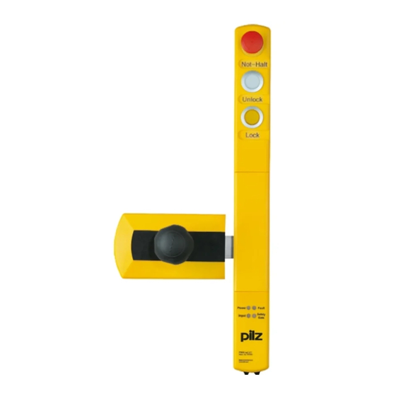
Escape release for fast manual release of the guard locking in emergency situations from within the danger zone (revolving gates and swing gates) Suitable for left and right hinged safety gates Note: The handle unit PSEN sg2c actuator is only suitable for revolving gates and swing gates. Plug-in spring-loaded terminals LED indicator for: –... -
Page 8: Safety
Are familiar with the basic regulations concerning health and safety / accident preven- tion Have read and understood the information provided in this description under "Safety" And have a good knowledge of the generic and specialist standards applicable to the specific application. Operating Manual PSEN sg2c 1003267-EN-04... -
Page 9: Warranty And Liability
The operator has to consider this in the hazard analysis and he must de- termine possible countermeasures. Operating Manual PSEN sg2c 1003267-EN-04... -
Page 10: Function Description
This enables easier access for cleaning staff once the shift has ended, for example. The guard locking element is disengaged from the bolt tongue as soon as there is a high signal at terminals X1-6 and X1-7 or X2-6 and X2-7. Operating Manual PSEN sg2c 1003267-EN-04... -
Page 11: Escape Release
[2] detaches from the locked position and lifts up- wards. The swivel piece [3] folds downwards. The bolt tongue [4] behind the swivel piece is released. The safety gate can be opened immediately, enabling the operator to leave the danger zone. Operating Manual PSEN sg2c 1003267-EN-04... - Page 12 Please note that the cover of the escape release has to be checked and re- installed after operation. Operating Manual PSEN sg2c 1003267-EN-04...
-
Page 13: Auxiliary Release
Please note that the cover of the escape release has to be checked and re- installed after operation. Operating Manual PSEN sg2c 1003267-EN-04... -
Page 14: Restart Interlock
(see illustration). As a result, the guard locking element cannot engage in the bolt tongue, the guard locking device is not activated and the machine is prevented from restarting. The padlock's shackle diameter may be max. 8 mm. Operating Manual PSEN sg2c 1003267-EN-04... -
Page 15: Holding Forces
The maximum holding forces that can be used to lock the safety gate are stated in the tech- nical details. A distinction is made between the following holding forces: Holding force in pan direction and Holding force in closing direction Holding force in closing direction Holding force in pan direction Operating Manual PSEN sg2c 1003267-EN-04... -
Page 16: Pushbutton
Operating a pushbutton switches the pushbutton output – The LEDs of the pushbuttons can be operated via the LED inputs. Further information on the different types can be found in the section entitled Device types [ 17]. Operating Manual PSEN sg2c 1003267-EN-04... -
Page 17: Device Types
Device types 21 different versions are available. They differ as follows: Number and quality of the pushbuttons Coded or uniquely coded With or without M12 connection for enabling switch PSEN sg2c-3xxx PSEN sg2c-5xxxxx PSEN sg2c-5xxxxx-M12/5 Operating Manual PSEN sg2c 1003267-EN-04... - Page 18 [2] Pushbutton 2: pushbutton for access request and release of the safety gate [3] E-STOP / or section stop pushbutton Type code: [1] [2] [3] PSEN sg2c - 3 L X X 2.2* 3 pushbuttons = 3 Pushbutton illuminated = L Pushbutton unilluminated = P...
- Page 19 [6] M12 connection for enabling switch Type code: [1] [2] [3] [4] [5] PSEN sg2c - 5 L X X L X - M12/5* 2.2* 5 pushbuttons = 5 Pushbutton illuminated = L Pushbutton unilluminated = P Key switch = B...
- Page 20 M12/5 ated switch illuminated pushbutton illuminated -5LPLLE Pushbut- Pushbut- Pushbut- Pushbut- E-Stop uniquely coded illuminated unillumin- illuminated illuminated ated -5LPKLE- Pushbut- Pushbut- Pushbut- E-Stop Yes uniquely M12/5 2.2 switch coded illuminated unillumin- illuminated ated Operating Manual PSEN sg2c 1003267-EN-04...
-
Page 21: Block Diagram
Function description Block diagram (Connector) 24 V 24 V Escape Release Pin Fig.: The connections shown in blue are available depending on the device type (see section entitled Device types [ 17]). Operating Manual PSEN sg2c 1003267-EN-04... -
Page 22: Wiring
The solenoid is no longer operated reliably. If the voltage for operating the solenoid is increased by the max. permitted tolerance to 26.4, there are still 20.4 V at the terminals of the last solenoid. The solenoid switches reliably. Operating Manual PSEN sg2c 1003267-EN-04... -
Page 23: Recommended Cable Cross Sections
(terminals X1-6 and X1-7) have to be carried individually, or several cables have to be used. If more than three safety switches are connected in series or cable runs over 60 m are required, please contact Pilz. The permitted conductor cross section is at least 0.25 mm². To have a higher conductor cross section, two cable cores can be inserted into a terminal. -
Page 24: Terminal Configuration
X1-10 E-STOP 1.1 E-STOP 1.1 E-STOP 1.1 X1-11 E-STOP 1.2 E-STOP 1.2 E-STOP 1.2 X1-12 E-STOP 2.1 E-STOP 2.1 E-STOP 2.1 X1-13 E-STOP 2.2 E-STOP 2.2 E-STOP 2.2 Operating Manual PSEN sg2c 1003267-EN-04... -
Page 25: Wiring The Connection Terminals
Strip the wire back 7 mm. Insert the screwdriver into the square hole. Insert the stripped wire into the square hole as far as it will go. Pull out the screwdriver. Check that the cable is firmly seated. Operating Manual PSEN sg2c 1003267-EN-04... -
Page 26: E-Stop Pushbutton Connection
INFORMATION Safety relays with a wide-range power supply or in AC device versions have internal potential isolation and are not suitable as evaluation devices. Only safety relays with a 24 VDC supply voltage are suitable. Operating Manual PSEN sg2c 1003267-EN-04... -
Page 27: Connection To Evaluation Devices
When the solenoid is operated in single-channel, only a safety level of PL d (Cat. 2)/SIL CL 2 can be achieved. To achieve PL e (Cat. 4/SIL CL 3, the solenoid must have dual-channel op- eration, e. g. via safe pulsed semiconductor outputs with high current load capacity (0.9 A for 50 ms). Operating Manual PSEN sg2c 1003267-EN-04... -
Page 28: Series Connection
To achieve PL e (Cat. 4)/SIL CL 3, the solenoid must have dual-channel op- eration. For applications with single-channel operation of the solenoid (up to PL d/SIL CL 2) a mo- mentarily overloadable safe output (1.8 A for 50 ms) can be used. Operating Manual PSEN sg2c 1003267-EN-04... - Page 29 Wiring The device can be switched in series with all safety switches from Pilz. In the connection example, the safety switch guard locking device is activated / deactivated via access re- quest (X1-5). The maximum switching current of the solenoid is present only while switch- ing the solenoids for about 50 ms.
-
Page 30: Installation
The handle unit should be protected from unauthorised removal and from contamination. CAUTION! Safety switch and handle unit – Should not be exposed to heavy shock or vibration – Should not be used as a limit stop Operating Manual PSEN sg2c 1003267-EN-04... -
Page 31: Initial Installation Of Safety Switch
Prepare 9 mm hole for the escape release and attach profile nuts to the aluminium pro- file (see also Dimensions for the drill holes [ 39]). The escape release does not require a drill hole. Operating Manual PSEN sg2c 1003267-EN-04... - Page 32 – If the actuator guide plate is installed using only the unprotected screws [1] accessible from the side, then one-way screws must be used for manipulation protection. – If the screws used under the bolt tongue [2] are protected against manipulation, then this is not necessary. Operating Manual PSEN sg2c 1003267-EN-04...
- Page 33 Position cable and screw on the strain relief plate (torque setting Ma 0.9 Nm +/- 0.1 (8 in-lbs)). Fix housing cover with screws (torque setting Ma 1.7 Nm +/- 0.1 (15 in-lbs)). Move the rubber seal along the cables and position it in the housing. Screw pressure screw on the thread. Operating Manual PSEN sg2c 1003267-EN-04...
- Page 34 Initial installation of handle unit [ INFORMATION If the escape or auxiliary release pin is not inserted into the swivel piece correctly, commissioning of the PSENsgate will be aborted and an error code will be issued. Operating Manual PSEN sg2c 1003267-EN-04...
- Page 35 45 mm and then be used for the auxiliary release. The auxiliary release pin is also avail- able as an accessory (see order references for Accessories [ 85]). NOTICE Please note that the escape release pin must not be shorter than 45 mm, to guarantee the full holding force. Operating Manual PSEN sg2c 1003267-EN-04...
-
Page 36: Initial Installation Of Handle Unit
Re-attach the screw with a torque setting of 2 Nm +/-0.1. Use an appropriate screw ad- hesive (e.g. Loctite 2700) to protect the screw from working loose. Fig.: Handle unit and actuator with screw Operating Manual PSEN sg2c 1003267-EN-04... -
Page 37: Labelling The Pushbuttons
Initial installation of handle unit [ Initial installation of safety switch [ 31]. Labelling the pushbuttons Colour covers are supplied with the PSEN sg2c Unit; these must be attached to the push- buttons, based on their function (see also order references for Accessories [ 85]). - Page 38 The fields below the pushbuttons can be used for inscribing the pushbuttons. The pushbut- tons can be written with a lettering device for 12 mm lettering band or with 32 x 10 mm la- bels (e.g. AVERY(R) article number: 3320). Operating Manual PSEN sg2c 1003267-EN-04...
-
Page 39: Dimensions In Mm
Drill holes (29,5) ± ± ø ± ± 22,5 ± 74,75 ± ± ± The bore diameter for all drill holes = M5. Exception: Drill hole for the escape release (see value stated in the drawing). Operating Manual PSEN sg2c 1003267-EN-04... -
Page 40: Psen Sg2C-3Xxx
Installation 6.5.2 PSEN sg2c-3xxx 74,5 46,3 49,7 108,2 44,2 ± 146,5 Operating Manual PSEN sg2c 1003267-EN-04... -
Page 41: Psen Sg2C-5Xxxxx
Installation 6.5.3 PSEN sg2c-5xxxxx 74,5 49,7 46,3 108,2 44,2 ± 146,5 Operating Manual PSEN sg2c 1003267-EN-04... -
Page 42: Psen Sg2C-5Xxxxx-M12/5
Installation 6.5.4 PSEN sg2c-5xxxxx-M12/5 74,5 49,7 46,3 18,2 108,2 44,2 ± 146,5 Operating Manual PSEN sg2c 1003267-EN-04... -
Page 43: Adjustment
Always check the function of the safety switch in conjunction with the handle unit with actuator, using one of the approved evaluation devices. Operating Manual PSEN sg2c 1003267-EN-04... -
Page 44: Maintenance
If necessary, re-adjust the handle unit with actuator. Otherwise no maintenance work needs to be performed on the interlocking and guard lock- ing system PSEN sg2c. Please return any faulty devices to Pilz. Operating Manual PSEN sg2c 1003267-EN-04... -
Page 45: Operation
Teaching in the actuator PSEN sg2c-xxx (coded version) Any corresponding Pilz actuator (see Technical details) is detected as soon as it is brought into the response range. PSEN sg2c-xxx 2.2 (uniquely coded version) The first corresponding actuator to be detected by the safety switch (see Technical de- tails) is taught in automatically as soon as it is brought into the response range. - Page 46 (see Terminal assignment) by applying an external +24 VDC. Pushbutton LED [4] can be used depending on the application. It is operated via the in- put (see Terminal assignment) by applying an external +24 VDC. Operating Manual PSEN sg2c 1003267-EN-04...
-
Page 47: Status Table
* The guard locking element can be engaged either by pressing the pushbutton key for ac- tivating the guard locking of the safety gate or by operating the input X 1-8. Legend LED on LED flashes LED off Operating Manual PSEN sg2c 1003267-EN-04... -
Page 48: Toggle Normal/Unlock Mode
After an error that was signalled by the red "Device" LED the device can be restarted by a reset: Rectify the error. Press the pushbutton for access request [2] and hold the pushbutton for at least 5 seconds. Operating Manual PSEN sg2c 1003267-EN-04... -
Page 49: Remedy
"Safety Gate" LED lights up Wrong actuator, e.g. 1.1- Insert correct actuator and guard locking element coded actuators with 2.2- is engaged, but the outputs coded safety switch are not switching. Operating Manual PSEN sg2c 1003267-EN-04... - Page 50 V DC At least one of the two safety out- Check the wiring of terminals X1-3 and puts X1-3 and X1-4 have voltage X1-4, rectify the wiring error, then reset applied during system run-up Operating Manual PSEN sg2c 1003267-EN-04...
-
Page 51: Technical Details Order No. 570800-570804
24 V DC 24 V DC 24 V DC Input current range 5 mA 5 mA 5 mA E-STOP 570800 570802 570804 Number of N/C contacts – E-STOP release type Turn release Turn release – Operating Manual PSEN sg2c 1003267-EN-04... - Page 52 24 V 24 V 24 V Max. current 0,1 A 0,1 A 0,1 A Electrical life 1,000,000 cycles 1,000,000 cycles 1,000,000 cycles Mechanical life 1,000,000 cycles 1,000,000 cycles 1,000,000 cycles Contact material AgNi AgNi AgNi Operating Manual PSEN sg2c 1003267-EN-04...
- Page 53 10 - 55 Hz 10 - 55 Hz Amplitude 1 mm 1 mm 1 mm Shock stress In accordance with the standard EN 60068-2-27 EN 60068-2-27 EN 60068-2-27 Acceleration Duration 11 ms 11 ms 11 ms Operating Manual PSEN sg2c 1003267-EN-04...
- Page 54 Valox 553 Valox 553 Actuator Stainless steel 1.4301 Stainless steel 1.4301 Stainless steel 1.4301 Dimensions Height 465 mm 465 mm 465 mm Width 200 mm 200 mm 200 mm Depth 108 mm 108 mm 108 mm Operating Manual PSEN sg2c 1003267-EN-04...
- Page 55 195 mm Depth 108 mm 108 mm 108 mm Weight of actuator 1.390 g 1.390 g 1.390 g Weight 2.570 g 2.570 g 2.570 g Where standards are undated, the 2013 latest editions shall apply. Operating Manual PSEN sg2c 1003267-EN-04...
-
Page 56: Technical Details Order No. 570806-570810
24 V DC 24 V DC 24 V DC Input current range 5 mA 5 mA 5 mA Section stop 570806 570808 570810 Number of N/C contacts – – Release type Turn release – – Operating Manual PSEN sg2c 1003267-EN-04... - Page 57 120 ms Delay-on de-energisation Inputs typ. 15 ms 15 ms 15 ms Inputs max. 20 ms 20 ms 20 ms Actuator typ. 30 ms 30 ms 30 ms Actuator max. 260 ms 260 ms 260 ms Operating Manual PSEN sg2c 1003267-EN-04...
- Page 58 Protection type Housing IP54 IP54 IP54 Mechanical data 570806 570808 570810 Escape release available yes Mechanical life 200,000 cycles 200,000 cycles 200,000 cycles Max. holding force in clos- ing direction 1000 N 1000 N 1000 N Operating Manual PSEN sg2c 1003267-EN-04...
- Page 59 195 mm Depth 108 mm 108 mm 108 mm Weight of actuator 1.390 g 1.390 g 1.390 g Weight 2.570 g 2.570 g 2.570 g Where standards are undated, the 2013 latest editions shall apply. Operating Manual PSEN sg2c 1003267-EN-04...
-
Page 60: Technical Details Order No. 570812-570816
24 V DC 24 V DC 24 V DC Input current range 5 mA 5 mA 5 mA E-STOP 570812 570814 570816 Number of N/C contacts – E-STOP release type Turn release Turn release – Operating Manual PSEN sg2c 1003267-EN-04... - Page 61 24 V 24 V 24 V Max. current 0,1 A 0,1 A 0,1 A Electrical life 1,000,000 cycles 1,000,000 cycles 1,000,000 cycles Mechanical life 1,000,000 cycles 1,000,000 cycles 1,000,000 cycles Contact material AgNi AgNi AgNi Operating Manual PSEN sg2c 1003267-EN-04...
- Page 62 10 - 55 Hz 10 - 55 Hz Amplitude 1 mm 1 mm 1 mm Shock stress In accordance with the standard EN 60068-2-27 EN 60068-2-27 EN 60068-2-27 Acceleration Duration 11 ms 11 ms 11 ms Operating Manual PSEN sg2c 1003267-EN-04...
- Page 63 Valox 553 Valox 553 Actuator Stainless steel 1.4301 Stainless steel 1.4301 Stainless steel 1.4301 Dimensions Height 555 mm 555 mm 555 mm Width 200 mm 200 mm 200 mm Depth 108 mm 108 mm 108 mm Operating Manual PSEN sg2c 1003267-EN-04...
- Page 64 195 mm Depth 108 mm 108 mm 108 mm Weight of actuator 1.390 g 1.390 g 1.390 g Weight 2.670 g 2.670 g 2.670 g Where standards are undated, the 2013 latest editions shall apply. Operating Manual PSEN sg2c 1003267-EN-04...
-
Page 65: Technical Details Order No. 570818-570822
Input current range 5 mA 5 mA 5 mA E-STOP 570818 570820 570822 Number of N/C contacts – – Section stop 570818 570820 570822 Number of N/C contacts – – Release type Turn release – – Operating Manual PSEN sg2c 1003267-EN-04... - Page 66 120 ms Delay-on de-energisation Inputs typ. 15 ms 15 ms 15 ms Inputs max. 20 ms 20 ms 20 ms Actuator typ. 30 ms 30 ms 30 ms Actuator max. 260 ms 260 ms 260 ms Operating Manual PSEN sg2c 1003267-EN-04...
- Page 67 Protection type Housing IP54 IP54 IP54 Mechanical data 570818 570820 570822 Escape release available yes Mechanical life 200,000 cycles 200,000 cycles 200,000 cycles Max. holding force in clos- ing direction 1000 N 1000 N 1000 N Operating Manual PSEN sg2c 1003267-EN-04...
- Page 68 195 mm Depth 108 mm 108 mm 108 mm Weight of actuator 1.390 g 1.390 g 1.390 g Weight 2.670 g 2.670 g 2.670 g Where standards are undated, the 2013 latest editions shall apply. Operating Manual PSEN sg2c 1003267-EN-04...
-
Page 69: Technical Details Order No. 570824-570828
24 V DC 24 V DC 24 V DC Input current range 5 mA 5 mA 5 mA E-STOP 570824 570826 570828 Number of N/C contacts – E-STOP release type Turn release Turn release – Operating Manual PSEN sg2c 1003267-EN-04... - Page 70 24 V 24 V 24 V Max. current 0,1 A 0,1 A 0,1 A Electrical life 1,000,000 cycles 1,000,000 cycles 1,000,000 cycles Mechanical life 1,000,000 cycles 1,000,000 cycles 1,000,000 cycles Contact material AgNi AgNi AgNi Operating Manual PSEN sg2c 1003267-EN-04...
- Page 71 10 - 55 Hz 10 - 55 Hz Amplitude 1 mm 1 mm 1 mm Shock stress In accordance with the standard EN 60068-2-27 EN 60068-2-27 EN 60068-2-27 Acceleration Duration 11 ms 11 ms 11 ms Operating Manual PSEN sg2c 1003267-EN-04...
- Page 72 Valox 553 Valox 553 Actuator Stainless steel 1.4301 Stainless steel 1.4301 Stainless steel 1.4301 Dimensions Height 568 mm 568 mm 568 mm Width 200 mm 200 mm 200 mm Depth 108 mm 108 mm 108 mm Operating Manual PSEN sg2c 1003267-EN-04...
- Page 73 195 mm Depth 108 mm 108 mm 108 mm Weight of actuator 1.390 g 1.390 g 1.390 g Weight 2.690 g 2.690 g 2.690 g Where standards are undated, the 2013 latest editions shall apply. Operating Manual PSEN sg2c 1003267-EN-04...
-
Page 74: Technical Details Order No. 570830-570834
24 V DC 24 V DC 24 V DC Input current range 5 mA 5 mA 5 mA Section stop 570830 570832 570834 Number of N/C contacts – – Release type Turn release – – Operating Manual PSEN sg2c 1003267-EN-04... - Page 75 120 ms Delay-on de-energisation Inputs typ. 15 ms 15 ms 15 ms Inputs max. 20 ms 20 ms 20 ms Actuator typ. 30 ms 30 ms 30 ms Actuator max. 260 ms 260 ms 260 ms Operating Manual PSEN sg2c 1003267-EN-04...
- Page 76 Protection type Housing IP54 IP54 IP54 Mechanical data 570830 570832 570834 Escape release available yes Mechanical life 200,000 cycles 200,000 cycles 200,000 cycles Max. holding force in clos- ing direction 1000 N 1000 N 1000 N Operating Manual PSEN sg2c 1003267-EN-04...
- Page 77 195 mm Depth 108 mm 108 mm 108 mm Weight of actuator 1.390 g 1.390 g 1.390 g Weight 2.690 g 2.690 g 2.690 g Where standards are undated, the 2013 latest editions shall apply. Operating Manual PSEN sg2c 1003267-EN-04...
-
Page 78: Technical Details Order No. 570880-570884
24 V DC 24 V DC 24 V DC Input current range 5 mA 5 mA 5 mA E-STOP 570880 570882 570884 Number of N/C contacts E-STOP release type Turn release Turn release Turn release Operating Manual PSEN sg2c 1003267-EN-04... - Page 79 120 ms Delay-on de-energisation Inputs typ. 15 ms 15 ms 15 ms Inputs max. 20 ms 20 ms 20 ms Actuator typ. 30 ms 30 ms 30 ms Actuator max. 260 ms 260 ms 260 ms Operating Manual PSEN sg2c 1003267-EN-04...
- Page 80 Protection type Housing IP54 IP54 IP54 Mechanical data 570880 570882 570884 Escape release available yes Mechanical life 200,000 cycles 200,000 cycles 200,000 cycles Max. holding force in clos- ing direction 1000 N 1000 N 1000 N Operating Manual PSEN sg2c 1003267-EN-04...
- Page 81 195 mm Depth 108 mm 108 mm 108 mm Weight of actuator 1.390 g 1.390 g 1.390 g Weight 2.570 g 2.670 g 2.690 g Where standards are undated, the 2013 latest editions shall apply. Operating Manual PSEN sg2c 1003267-EN-04...
-
Page 82: Safety Characteristic Data
Cat. 4 SIL CL 3 2,08E-09 – – cycles NOTICE Be sure that you observe the mechanical life. The safety characteristic data are only valid as long as the values of mechanical life are met. Operating Manual PSEN sg2c 1003267-EN-04... -
Page 83: Order Reference
PSEN sg2c-5LBKLE- Safety gate system (transponder technology) with safe inter- 570 826 M12/5 unit locking and guard locking, 2 pushbuttons illuminated, 1 key-op- erated pushbutton, 1 key switch, 1 E-STOP pushbutton, con- nection for enabling switch Operating Manual PSEN sg2c 1003267-EN-04... -
Page 84: Safety Switch
PSEN sg2c-5LBLLE Safety switch, 3 pushbuttons illuminated, 1 key-operated push- 570 815 switch button, 1 E-STOP pushbutton PSEN sg2c-5LPLLS Safety switch, 3 pushbuttons illuminated, 1 pushbutton unillu- 570 817 switch minated, 1 section stop pushbutton Operating Manual PSEN sg2c 1003267-EN-04... -
Page 85: Handle Unit With Actuator
18.3 Handle unit with actuator Product type Features Order No. PSEN sg2c actuator Handle unit with actuator 570 890 PSEN sg2c actuator 2.2 Handle unit with uniquely coded actuator 570 891 18.4 Accessories Product type Features Order No. PSEN sg2 cover... - Page 86 Order reference Product type Features Order No. PSEN sg auxiliary release Pin for auxiliary release 570 871 PSEN sg color covers Colour covers for illuminated buttons 570 875 (pushbutton) Operating Manual PSEN sg2c 1003267-EN-04...
-
Page 87: Supplementary Data
2) this product must accept any interference received, including interference that may cause undesired operation. Changes or modifications made to this product not expressly approved by Pilz may void the FCC authorization to operate this equipment. NOTE: This equipment has been tested and found to comply with the limits for a Class A digital device, pursuant to Part 15 of the FCC Rules. - Page 88 Front cover Support Technical support is available from Pilz round the clock. Americas Australia Scandinavia Brazil +61 3 95446300 +45 74436332 +55 11 97569-2804 Spain Canada Europe +34 938497433 +1 888-315-PILZ (315-7459) Austria Switzerland Mexico +43 1 7986263-0 +41 62 88979-30...
Need help?
Do you have a question about the PSEN sg2c and is the answer not in the manual?
Questions and answers