
Related Manuals for Aaeon PCM-3336


Summary of Contents for Aaeon PCM-3336
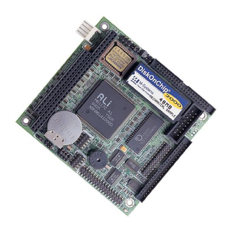
- Page 1 PCM-3336 386SX-40 PC/104 CPU Card With LCD & DiskOnChip® PCM-3336 Rev. A Manual Part No. 2007333603 Printed in Taiwan September 2003...
-
Page 2: Copyright Notice
AAEON assumes no liabilities resulting from errors or omissions in this document, or from the use of the information contained herein. AAEON reserves the right to make changes in the product design without notice to its users. -
Page 3: Packing List
IBM, PC/AT, PS/2, and VGA are trademarks of International Business Machines Corporation. Packing List Before you begin installing your card, please make sure that the following materials have been shipped: • 1 PCM-3336 PC/104 CPU Card • 1 Manual • Jumper Cap •... -
Page 4: Table Of Contents
P C / 1 0 4 C P U C a r d P C M - 3 3 3 6 Contents Chapter 1 General Information 1.1 Introduction ................1-2 1.2 Features................... 1-3 1.3 Specifications................1-4 Chapter 2 Quick Installation Guide 2.1 Safety Precautions.............. - Page 5 P C / 1 0 4 C P U C a r d P C M - 3 3 3 6 2.18 Parallel Port (CN8)..............2-13 2.19 Serial Port (CN9 & CN11)............ 2-14 2.20 Floppy Drive Connector (CN10).......... 2-15 Chapter 3 AMI BIOS Setup 3.1 System Test and Initialization.
-
Page 6: Chapter 1 General Information
P C / 1 0 4 C P U C a r d P C M - 3 3 3 6 Chapter General Information Chapter 1 General Information 1- 1... -
Page 7: Introduction
SPP, ECP and EPP modes, and IDE HDD interface and a floppy disk controller. With its industrial grade reliability, the PCM-3336 can operate continuously at temperature up to 140 ℉(60℃). The PCM-3336 is specially designed as a compact all-in-one... - Page 8 P C / 1 0 4 C P U C a r d P C M - 3 3 3 6 1.2 Features Onboard ALi M6117C, Intel 386SX-40 compatible CPU Onboard 8Mbytes EDO DRAM C&T 65545 LCD controller with 512KB display memory Chapter 1 General Information 1 - 3...
-
Page 9: Specifications
P C / 1 0 4 C P U C a r d P C M - 3 3 3 6 1.3 Specifications System ALi M6117C, Intel 80386SX-40 compatible Chipset ALi M6117C IO Chipset ITE-8661 BIOS AMI 128KB Flash BIOS. System Memory Onboard 8MB EDO DRAM Enhanced IDE... - Page 10 P C / 1 0 4 C P U C a r d P C M - 3 3 3 6 Support DiskOnChip up to 1GB 7 DMA channels (8237 equivalent) Interrupt 15 interrupt levels (8259 equivalent) Display Chipset C&T 65545 Display Memory 512KB Display Type...
-
Page 11: Chapter 2 Quick Installation Guide
P C / 1 0 4 C P U C a r d P C M - 3 3 3 6 Chapter Quick Installation Guide Chapter 2 Quick Installation Guide 2 - 1... -
Page 12: Safety Precautions
P C / 1 0 4 C P U C a r d P C M - 3 3 3 6 2.1 Safety Precautions Always completely disconnect the power cord from your board whenever you are working on it. Do not make connections while the power is on, because a sudden rush of power can damage sensitive electronic components. -
Page 13: Board Layout
P C / 1 0 4 C P U C a r d P C M - 3 3 3 6 2.2 Board Layout Chapter 2 Quick Installation Guide 2 - 3... -
Page 14: Board Dimension
P C / 1 0 4 C P U C a r d P C M - 3 3 3 6 2.3 Board Dimension Chapter 2 Quick Installation Guide 2 - 4... -
Page 15: List Of Jumpers
P C / 1 0 4 C P U C a r d P C M - 3 3 3 6 2.4 List of Jumpers The board has a number of jumpers that allow you to configure your system to suit your application. The table below shows the function of each of the board's jumpers: Jumpers Label... -
Page 16: List Of Connectors
P C / 1 0 4 C P U C a r d P C M - 3 3 3 6 2.5 List of Connectors The board has a number of connectors that allow you to configure your system to suit your application. The table below shows the function of each of the board's connectors: Connectors Label... -
Page 17: Setting Jumpers
P C / 1 0 4 C P U C a r d P C M - 3 3 3 6 2.6 Setting Jumpers You configure your card to match the needs of your application by setting jumpers. A jumper is the simplest kind of electric switch. It consists of two metal pins and a small metal clip (often protected by a plastic cover) that slides over the pins to connect them. -
Page 18: Hdd Led (J1)
P C / 1 0 4 C P U C a r d P C M - 3 3 3 6 2.7 HDD LED (J1) You can connect a LED to indicate that an IDE device is in use. Function -R/W IDE (LED Cathode) Pull high (LED Anode) 2.8 Reset Switch (J2) -
Page 19: Lcd Power Select (J4)
P C / 1 0 4 C P U C a r d P C M - 3 3 3 6 2.10 LCD Power Select (J4) You can use J4 jumper to select the voltage setting for the LCD power. To select a certain voltage level close the corresponding pin numbers with a pin cap. -
Page 20: Rs-232/422/485 Com2 Setting (J5 & J6)
P C / 1 0 4 C P U C a r d P C M - 3 3 3 6 2.13 RS-232/422/485 COM2 Setting (J5 & J6) Function 1-2, 4-5, 7-8, 10-11 RS-232 (Default) 2-3, 5-6, 8-9, 11-12 RS-422 2-3, 5-6, 8-9, 11-12 RS-485 2.14 IDE Hard Drive Connector (CN1) -
Page 21: Keyboard Connector (Cn2)
P C / 1 0 4 C P U C a r d P C M - 3 3 3 6 2.15 Keyboard Connector (CN2) Signal Signal KBDATA KBCLOCK KGND KVcc MSDATA MSCLOCK 2.16 Display Connector (CN4 & CN6) Signal Signal GREEN BLUE... -
Page 22: Power Supply Connector (Cn5)
P C / 1 0 4 C P U C a r d P C M - 3 3 3 6 LCD clock (SHCLK) FLM (V SYS) ACDCLK (M) LP (H SYS) ENABKL ASHCLK 2.17 Power Supply Connector (CN5) Signal +12V Chapter 2 Quick Installation Guide 2 - 12... -
Page 23: Parallel Port (Cn8)
P C / 1 0 4 C P U C a r d P C M - 3 3 3 6 2.18 Parallel Port (CN8) Signal Signal Strobe PERR PINIT PSLIN PACK PBUSY PSEL Chapter 2 Quick Installation Guide 2 - 13... -
Page 24: Serial Port (Cn9 & Cn11)
P C / 1 0 4 C P U C a r d P C M - 3 3 3 6 2.19 Serial Port (CN9 & CN11) COM1 Connector (CN9) Signal DLSD1 SIN1 TxD 1 DTR1 DSR 1 RTS 1 CTS 1 RI 1 COM2 Connector (CN11) -
Page 25: Floppy Drive Connector (Cn10)
P C / 1 0 4 C P U C a r d P C M - 3 3 3 6 2.20 Floppy Drive Connector (CN10) Signal Signal 1 ~ 33 DENSEL (odd) 4, 6 INDEX MTRA DRVB DRVA MTRB STEP WDATA WGATE... -
Page 26: Chapter 3 Ami Bios Setup
P C / 1 0 4 C P U C a r d P C M - 3 3 3 6 Chapter BIOS Setup Chapter 3 AMI BIOS Setup... -
Page 27: System Test And Initialization
The CMOS memory has lost power and the configuration information has been erased. The PCM-3336 CMOS memory has an integral lithium battery backup for data retention. However, you will need to replace the complete unit when it finally runs down. -
Page 28: Ami Bios Setup
P C / 1 0 4 C P U C a r d P C M - 3 3 3 6 3.2 AMI BIOS setup AMI BIOS ROM has a built-in Setup program that allows users to modify the basic system configuration. This type of information is stored in battery-backed CMOS RAM so that it retains the Setup information when the power is turned off. -
Page 29: Auto Configuration With Optimal Settings
P C / 1 0 4 C P U C a r d P C M - 3 3 3 6 Advanced Chipset Setup Use this menu to change the values in the chipset registers and optimize your system performance. PCI/Plug and Play Configurations This entry appears if your system supports PnP/PCI. -
Page 30: Standard Cmos Setup
P C / 1 0 4 C P U C a r d P C M - 3 3 3 6 3.3 Standard CMOS Setup When you choose the Standard CMOS Setup option from the INITIAL SETUP SCREEN menu, the screen shown below is displayed. -
Page 31: Advanced Cmos Setup
P C / 1 0 4 C P U C a r d P C M - 3 3 3 6 3.4 Advanced CMOS Setup By choosing the Advanced CMOS Setup option from the INITIAL SETUP SCREEN menu, the screen below is displayed. Chapter3 AMI BIOS Setup 3 - 6... -
Page 32: Advanced Chipset Setup
P C / 1 0 4 C P U C a r d P C M - 3 3 3 6 3.5 Advanced Chipset Setup By choosing the Advanced Chipset Setup option from the INITIAL SETUP SCREEN menu, the screen below is displayed. Chapter3 AMI BIOS Setup 3 - 7... -
Page 33: Pci/Plug And Play Setup
P C / 1 0 4 C P U C a r d P C M - 3 3 3 6 3.6 PCI/Plug and Play Setup By choosing the PCI/Plug and Play Setup from the INITIAL SETUP SCREEN menu, the screen below is displayed. Chapter3 AMI BIOS Setup 3 - 8... -
Page 34: Peripheral Setup
P C / 1 0 4 C P U C a r d P C M - 3 3 3 6 3.7 Peripheral Setup By choosing the Peripheral Setup from the INITIAL SETUP SCREEN menu, the screen below is displayed. Chapter3 AMI BIOS Setup 3 - 9...
Need help?
Do you have a question about the PCM-3336 and is the answer not in the manual?
Questions and answers