Table of Contents
Advertisement
Quick Links
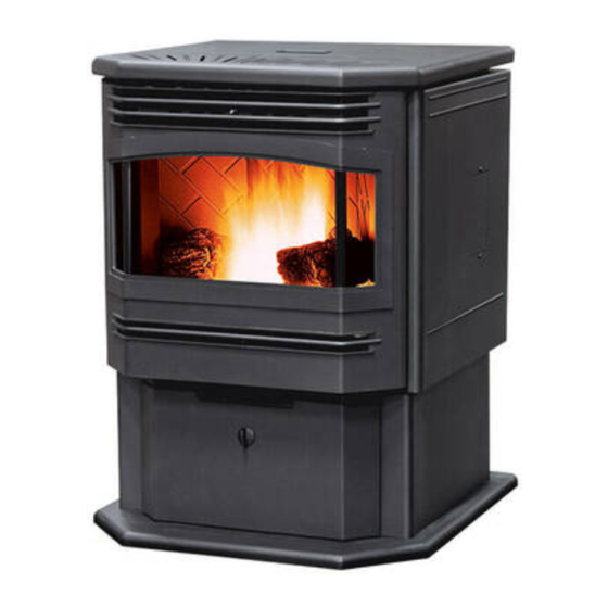
OLYMPIAN
F R E E - S T A N D I N G A N D F I R E P L A C E I N S E R T
TECHNICAL MANUAL
PLEASE READ THIS ENTIRE MANUAL BEFORE INSTALLATION AND USE OF THIS
PELLET-BURNING ROOM HEATER. FAILURE TO FOLLOW THESE INSTRUCTIONS
COULD RESULT IN PROPERTY DAMAGE, BODILY INJURY OR EVEN DEATH.
Contact your building or fire officials about restrictions and
installation inspection requirements in your area.
50-1739
Advertisement
Table of Contents

Related Manuals for Enviro OLYMPIAN


Summary of Contents for Enviro OLYMPIAN
- Page 1 OLYMPIAN F R E E - S T A N D I N G A N D F I R E P L A C E I N S E R T TECHNICAL MANUAL PLEASE READ THIS ENTIRE MANUAL BEFORE INSTALLATION AND USE OF THIS PELLET-BURNING ROOM HEATER.
-
Page 2: Table Of Contents
Table of Contents Safety Warnings & Recommendations....................3 Specifications..........................6 Rating Label Location......................6 Specifications........................6 Dimensions - Freestanding....................7 Dimensions - Fireplace Insert....................7 Installation.............................8 Deciding Where to Locate your Pellet Appliance..............8 Removing Pellet Stove From Pallet..................8 Clearances to Combustibles - Freestanding................9 Alcove Clearances - Freestanding..................9 Clearances to Combustibles - Fireplace Insert...............10 Installation of Pedestal and Leveling Legs - Fireplace Insert..........10 Installing Hopper Cover and Adjusting Hopper Height - Fireplace Insert.........10... -
Page 3: Safety Warnings & Recommendations
To prevent the possibility of a fire, ensure that the appliance is properly installed by adhering to the installation instructions. An ENVIRO dealer will be happy to assist you in obtaining information with regards to your local building codes and installation restrictions. - Page 4 GLASS: Do not abuse the glass by striking or slamming the door. Do not attempt to operate the stove with broken glass. The stove uses ceramic glass. Replacement glass must be purchased from an ENVIRO dealer. Do not attempt to open the door and clean the glass while the unit is in operation or if glass is hot.
- Page 5 Safety Warnings & Recommendations FRESH AIR: Outside Fresh Air connection is optional. Fresh Air must be connected to all units installed in “Air Tight Homes” or where required by local codes. Consider all large air moving devices when installing your unit and provide room air accordingly. NOTE: Extractor fans when operating in the same room or space as the appliance, may cause problems.
-
Page 6: Specifications
Specifications ating abel ocation Freestanding: The rating label is located on the inside of the hopper lid. Fireplace Insert and Built-In Heater: The rating label is located on the hopper cover. pecificationS... -
Page 7: Dimensions - Freestanding
Specifications imenSionS reeStanding " (826mm) " (632mm) Figure 1: Olympian Freestanding Dimensions. imenSionS ireplace nSert " (605mm) " " (326mm) (604mm) " (583mm) Figure 2: Olympian Fireplace Insert Dimensions. -
Page 8: Installation
Installation eciding here to ocate your ellet ppliance 1. Do not install the stove in a bedroom or room where people sleep in. 2. Locate the stove in a large and open room that is centrally located in the house. This will optimize heat circulation. -
Page 9: Clearances To Combustibles - Freestanding
6“ (150 mm) in front for ember protection. lcove learanceS reeStanding Minimum Width 36" (914mm) Minimum Height 48" (1219mm) Maximum Depth 30" (762mm) Figure 7: Alcove Clearances Freestanding Olympian. -
Page 10: Clearances To Combustibles - Fireplace Insert
There are two parts to the Olympian insert pedestal and they can be found inside the hopper. Place unit on its back. Two (2) hex head screws are used on each side of the pedestal (refer to Figure 8). Using a ”... -
Page 11: Mobile Home Installation - Freestanding
Installation Figure 10: Hopper Cover Screw Placement. Figure 11: Hopper Extension Screw Placement. obile nStallation reeStanding ● Secure the heater to the floor using the holes in the pedestal of the appliance. ● Ensure the unit is electrically grounded to the chassis of your home (permanently). WARNING: Do not install in a room people sleep in. -
Page 12: Vent Termination Requirements
Installation ermination equirementS IT IS RECOMMENDED THAT YOUR PELLET STOVE BE INSTALLED BY AN AUTHORIZED DEALER/INSTALLER. Table 2: Use in conjunction with Figure 13 for allowable exterior vent termination locations. Letter Minimum Clearance Description 24 in (61 cm) Above grass, top of plants, wood, or any other combustible materials. 48 in (122 cm) Beside/below any door or window that may be opened. -
Page 13: Exhaust And Fresh Air Intake Locations
" (473mm) " (87mm) " (332mm) " " 1" (277mm) (156mm) (25mm) Figure 15: Olympian Insert Inlet and Outlet Location. " " 1" (291mm) (170mm) (25mm) Figure 14: Olympian Freestanding Inlet and Outlet Location. EXHAUST Freestanding Insert Base of unit to center of flue 18 ⅝”... -
Page 14: Corner Through Wall Installation - Freestanding
Installation orner hrough nStallation reeStanding Fresh Air Intake 3" (7.5 cm) Wall thimble manufactured by pellet vent manufacturer. 3" (7.5 cm) Figure 17: Corner Installation. orizontal xhauSt hrough nStallation reeStanding Vent installation: install vent at clearances specified by the vent manufacturer. A chimney connector shall not pass through an attic or roof space, closet or similar concealed spaces, or a floor, or ceiling. - Page 15 Installation Exhaust Tube 3" (75mm) or 4" (100mm) "PL" or "L" vent Wall Thimble 45° Elbow with screen or Termination Cap Fresh Air Intake High Temperature RTV Silicone Required Figure 18: Straight through wall Installation. 9. Install a vertical pipe, or if all requirements for direct venting are met, install vent termination.The stainless steel cap termination manufactured by the vent manufacturer is recommended.
-
Page 16: Vertical Rise With Horizontal Termination Installation (Recommended) - Freestanding
Installation ) - f ertical iSe With orizontal ermination nStallation ecommended reeStanding Termination cap 90°elbow Wall framing A 45° elbow may be used in place of the termination cap (or stainless steel termination hood). Vertical section of vent pipe Wall strap Horizontal frame for thimble Clean... -
Page 17: Inside Vertical Installations - Freestanding
Installation nSide ertical nStallationS reeStanding 1. Choose a stove location that is ideal. See the section “I nStallatIon eCIdIng Here to oCate your ellet .” PPlIanCe 2. Place unit hearth pad (if installed on Rain cap - ensure cap is at a carpeted surface) and least 2 feet (610mm) above space the unit in a manner... -
Page 18: Outside Vertical Installations - Freestanding
Installation utSide ertical nStallationS reeStanding To accomplish a outside vertical pipe installation, follow steps 1 through 5 in the “I nSIde ertICal nStallatIonS ” section and then finish it by performing the following (refer to Figure 23). reeStandIng 1. Install a tee with clean out on the outside of the house. 2. -
Page 19: Hearth Mount Installation - Freestanding
Figure 24: Hearth Mount - Side View. Seal plate (cover plate) SEISMIC RESTRAINT: All installation scenarios for the Enviro Olympian require the use of hold-down Existing masonry anchors (one on each side) flue Fixing to Concrete Floor: Vent pipe (single... -
Page 20: Installation With Exterior Mounted Exhaust Blower - Freestanding
Olympian can be equipped with an externally mounted exhaust blower (PART #50-492). This optional kit will include all components necessary to install the exhaust blower on any external vertical wall surface. Choose a location for your stove that meets the requirements stated in this manual and allows installation with the least amount of interference to house framing, plumbing, wiring, etc. - Page 21 Installation NOTE: Ensure that all vent connections are installed by placing three (3) screws evenly spaced and a small bead of high temperature silicone at each chimney connection. Also ensure that all vertical vent sections are properly supported and that all clearances to combustibles are maintained in accordance with the vent manufacturer’s specifications.
-
Page 22: Through Wall Vertical Installation With Exhaust Blower - Freestanding
Installation hrough ertical nStallation xhauSt loWer reeStanding Refer to I and I nStallatIon nStallatIon WItH xterIor ounted xHauSt loWer reeStandIng nStallatIon . Ensure that vent pipe is properly secured to wall using wall utSIde ertICal nStallatIonS reeStandIng straps. Maintain clearances to combustibles on vent pipe as well as unit. Rain Cap Roof sheathing Storm collar... -
Page 23: Masonry Fireplace Insert Installation - Fireplace Insert
If the fireplace insert does not fit into a zero clearance fireplace we recommend you use an ENVIRO freestanding model and install as a hearth mounted unit. Install a 3” (76 mm) flex pipe from the stove to the top of the chimney (see “I ”). -
Page 24: Installation And Removal Of Control Panel In The Surround Panel - Fireplace Insert
Installation nStallation and emoval of ontrol anel in urround anel ireplace nSert When installing the circuit board control panel into the surround panel, the surround does not need to be assembled. The circuit board will be found in the firebox. Place the circuit board control panel on the backside of the right surround panel so the hinge is on the outside and the top and bottom holes on the control panel line up with those on the... -
Page 25: Plated Trim Installation
Installation lated nStallation TO AVOID PERSONAL INJURY DO NOT REMOVE OR REPLACE TRIMS WHEN PELLET STOVE IS HOT! KIT COMPONENTS: Upper Cabinet Trim Quantity Description Left Cabinet Side Upper Cabinet Trim Lower Cabinet Trim Top Trim Lower Louver Cabinet Trim #8 nut plated (spares) TOOLS REQUIRED: #8 Hex Nut (x8) -
Page 26: Plated Door Installation
#8 hex nuts around the inside of the glass retainer. Ensure the four screws are also hand tight and close door. Clean all plated surfaces before starting the stove. See in r in the leanIng lated urFaCeS outIne leanIng and aIntenanCe Owner’s Manual. Figure 37: Inner side of Olympian door. -
Page 27: Thermostat Installation
Installation hermoStat nStallation 1. Install the wall thermostat in a location that is not to close too the unit but will effectively heat the desired area. 2. Install a 12 or 24 Volt Thermostat using an 18 x 2 gauge wire from the unit to the thermostat. If the unit has been placed in the HI / LOW mode, the unit will be taken to a low or idle setting when the thermostat is not calling for heat. - Page 28 Installation The easiest way to make sure that an efficient flame is achieved is to understand the characteristics of the fire. • A tall, lazy flame with dark orange tips requires more air – Open slider (pull out) slightly. • A short, brisk flame, like a blowtorch, has too much air –...
-
Page 29: Troubleshooting
Troubleshooting DO NOT: ● Service the stove with wet hands. The stove is an electrical appliance, which may pose a shock hazard if handled improperly. Only qualified technicians should deal with possible internal electrical failures. ● Do not remove from the firebox any screws without penetrating oil lubrication. WHAT TO DO IF: 1. - Page 30 Troubleshooting Poor Quality Fuel – Insufficient energy in the fuel to produce enough heat to keep the stove burning or operational. Exhaust Temperature Sensor failure. – Bypass sensor located on Exhaust Blower if stove now operates properly, the unit may require cleaning or a new sensor. Contact your local dealer for service. Check the fuse on the circuit board.
- Page 31 Troubleshooting 7. The convection blower will not function normally. Clean all grill openings at the back and below unit . Press the fan button; does the fan come on? Press again to verify that the blower turns on; if, not contact your local dealer for service.
-
Page 32: Wiring Diagram
Wiring Diagram Armor Cable Supplied Grey Optional Exterior Vacuum Exhaust Blower Grey Switch Black White White Combustion Blue Brown Blower Exhaust Temperature Sensor Power Cord Brown Ground Black 115V 115V White Black Black White 220V 220V Brown Blue Thermostat Common 5 Amp Ignitor Fuse... -
Page 33: Parts List - Components
NZ Power Cord - 220V 20-011 IEC Power Cord - 220V Log Set Control Panel Door 20-040 60° Exterior Exhaust Adaptor 50-096 Enviro Logo Gel Decal 50-322 Control Panel Touch Latch 50-323 Circuit Board Stand Offs 50-331 External Exhaust Kit - 220V 50-492... - Page 34 EMI Filter - 220V [Electrical] 50-1584 Control Panel (Freestanding) 50-2405 Control Panel Decal 50-1967 EMI Filter - 220V 50-1584 Olympian Owner’s Manual 50-1738 Olympian Technical Manual 50-1739 Circuit Board with Thermostat Switch - 220V 50-1964 Control Panel (Insert) 50-2404 Stainless Steel Burn Pot Liner - NZ...
-
Page 35: Parts List - Options
Parts List - Options Reference # Description Part # Body Trim Kit - Pewter (Freestanding) 50-620 Body Trim Kit - Gold (Freestanding) 50-621 Body Trim Kit - Antique Copper (Freestanding) 50-622 Door Cover - Painted 50-683 Door Cover - Pewter 50-623 Door Cover - Gold 50-624... -
Page 36: Parts Diagram - Components
Parts Diagram - Components OLYMPIAN - Components January 2008... -
Page 37: Parts Diagram - Freestanding Steel
Parts Diagram - Freestanding Steel... -
Page 38: Parts Diagram - Insert Steel
Parts Diagram - Insert Steel... -
Page 39: Installation Data Sheet
Installation Data Sheet The following information must be recorded by the installer for warranty purposes and future reference. NAME OF OWNER: NAME OF DEALER: _________________________________________ _________________________________________ ADDRESS: ADDRESS: _________________________________________ _________________________________________ _________________________________________ _________________________________________ _________________________________________ _________________________________________ PHONE:___________________________________ PHONE:___________________________________ MODEL:___________________________________ NAME OF INSTALLER: SERIAL NUMBER:___________________________ _________________________________________ DATE OF PURCHASE: _____________...
Need help?
Do you have a question about the OLYMPIAN and is the answer not in the manual?
Questions and answers