
Related Manuals for HAMPTON BAY Winfield


Summary of Contents for HAMPTON BAY Winfield
- Page 1 247 343 Winfield Ceiling Fan Owner’s Manual Winfield Ventilador de Techo de 1,37 Manual del Propietario...
- Page 2 Winfield by Hampton Bay ®...
-
Page 3: Table Of Contents
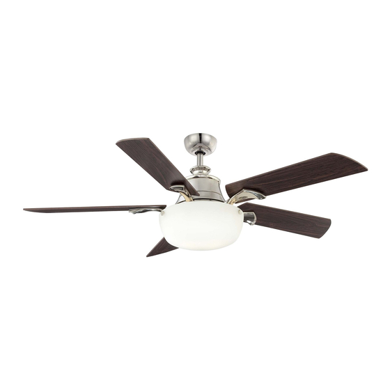
54” Winfield Thank you for purchasing our ceiling fan. This product has been manufactured with the highest standards of safety and quality. Ceiling Fan by Hampton Bay Date Purchased Table of Contents Store Purchased Safety Rules ....1 247-343 UL Model No. -
Page 4: Safety Rules
Safety Rules - Read and Save These Instructions To reduce the risk of electric shock, insure electricity has been turned off at the After making electrical connections, spliced conductors should be turned circuit breaker or fuse box before beginning. upward and pushed carefully up into outlet box. The wires should be spread apart with the grounded conductor and the equipment-grounding conductor All wiring must be in accordance with the National Electrical Code on one side of the outlet box and ungrounded conductor on the other side of... -
Page 5: Unpacking Your Fan
Unpacking Your Fan Unpack your fan and check the contents. You should have the following items: Set of blades (5) Mounting plate Blade Attachment Hardware (16 Screws, 16 Fiber Washers) Canopy assembly Light plate Ball/downrod assembly Glass shade Electrical Hardware Coupling cover 13 Watt GU24 CFL bulbs (2) (3 Plastic Wire Nuts) -
Page 6: Installing Your Fan
Installing Your Fan Provide Strong Support Figures 1~3 are examples of different ways to Tools Required mount the outlet box. Phillips screwdriver, straight slot screwdriver, step ladder and wire cutters. Recessed Ceiling Outlet Box Mounting Plate Mounting Options Figure 3 Outlet Box Note: You may need a longer downrod to If there isn't an existing ETL listed mounting box,... -
Page 7: Hanging The Fan
Hanging the Fan Align the holes at the bottom of the downrod Motor Wires with the holes in the coupling on top of the REMEMBER to turn off the power. Follow the motor housing (Figure 6). Carefully insert the Pin in Locked Ceiling Canopy clevis pin through the holes in the collar and Positioon... - Page 8 WARNING Installing Fan to ETL Listed Outlet Box THE TAB IN THE RING MUST REST IN THE the Electrical Box GROOVE OF THE HANGER BALL AS FIGURE 7. FAILURE TO PROPERLY SEAT THE TAB IN THE GROOVE COULD CAUSE DAMAGE TO WIRING. 120V WARNING Wires...
- Page 9 Making the Electrical WARNING SUPPLY CIRCUIT CHECK TO SEE THAT ALL CONNECTIONS ARE Connections TIGHT, INCLUDING GROUND, AND THAT NO BARE WIRE IS VISIBLE AT THE WIRE NUTS. EXCEPT FOR THE GROUND WIRE. Ground REMEMBER to disconnect the power. Conductor WARNING If you feel you do not have enough electrical wiring knowledge or experience, have your fan...
-
Page 10: Attaching The Fan Blades
Finishing the Fan Installation Outlet Box Screws Fiber Washers Blades Tuck connections neatly into ceiling outlet Ceiling box. Mounting Bracket Slide the canopy up to mounting bracket and place the key hole on the canopy over the screw on the mounting bracket, turn canopy Canopy Blade Arm until it locks in place at the narrow section of... - Page 11 Attaching the Mounting Blade Balancing Plate The following procedure should correct most fan Touching Ceiling wobble. Check after each step. Remove 1 of 3 screws from the mounting ring Check that all blade and blade bracket screws and loosen the other 2 screws. (Do not remove) are secure.
-
Page 12: Installing The Light Kit
Installing the Light Kit CAUTION BEFORE STARTING INSTALLATION, DISCONNECT THE POWER BY TURNING OFF THE CIRCUIT BREAKER OR REMOVING THE FUSE AT FUSE BOX. TURNING POWER OFF USING THE FAN SWITCH IS NOT SUFFICIENT TO PREVENT ELECTRIC SHOCK. While holding the light plate under your fan, locate two single white and black wires in the mounting plate labeled FOR LIGHT. -
Page 13: Operating Your Transmitter
Operating Your Transmitter Your DC brushless motor is equipped with a automatically learned type remote control. Restore power to ceiling fan and test the transmitter as below for proper operation: Install one 23A/12V battery (included). To prevent damage to transmitter, remove the battery if not used for long periods of time. - Page 14 E. SET code setting button: Follow the below steps to use the SET button Step 1 Turn on the AC power for the controller after finishing the fan installation. Step 2 Turn fan power on, press and hold SET button on the back of transmitter for 5 seconds within 60 seconds, the transmitter learning is completed after the light flashes twice.
- Page 15 NOTE Installing the Transmitter TO OPERATE THE REVERSE FUNCTION ON THIS Holder FAN, PRESS THE FOR/REV BUTTON WHILE THE FAN IS RUNNING. Remove the cover from the holder. Speed settings for warm or cool weather depend on factors such as the room size, ceiling height, Attach the holder to the wall with the two number of fans, and so on.
-
Page 16: Care Of Your Fan
Care of Your Fan Troubleshooting PROBLEM SOLUTION Here are some suggestions to help you maintain your fan. Fan will not start Check main and branch circuit fuses or breakers. Because of the fan's natural movement, some Check line wire connections to the fan and switch wire connections in connections may become loose. -
Page 17: Specifications
Specifications FAN SIZE SPEED VOLTS AMPS WATTS N.W. G.W. C.F. Minimum 0.06 2370.00 0.08 3006.00 8.71 kgs 10.06 kgs 54” 2.42’ 0.11 3493.00 Medium low (19.21 lbs) (22.19 lbs) Medium 0.16 12.1 3997.00 0.21 17.1 4647.00 Medium high 0.34 28.5 5671.00 HIGH These are approximate measures. -
Page 18: Warranty Information
Hampton Bay Lifetime Limited Warranty (lifetime warranty on motor) The Hampton Bay warrants the fan motor to be free from defects in workmanship and material present at time You must present a copy of the original purchase receipt to obtain warranty of shipment from the factory for a period of lifetime after the date of purchase by the original purchaser.
Need help?
Do you have a question about the Winfield and is the answer not in the manual?
Questions and answers