Table of Contents
Advertisement
Advertisement
Table of Contents

Subscribe to Our Youtube Channel
Related Manuals for Binary B-540-EXT-330-RS-IPW


Summary of Contents for Binary B-540-EXT-330-RS-IPW
- Page 1 HDBaseT EXTENDER B-540-EXT-330-RS-IPW INSTALLATION MANUAL Source | M (HDMI Ou...
- Page 2 IMPORTANT SAFETY INSTRUCTIONS To reduce the risk of fire or electric shock, read and follow all instructions and warnings in this manual. Keep this manual for future reference. 1. Do not expose this apparatus to rain or moisture. Do not expose this equipment to dripping or splashing, and ensure that no objects filled with liquids, such as vases, are placed on the equipment.
-
Page 3: Table Of Contents
3. Package Contents ................................4 4. Device Layout ..................................5 4.1. B-540-EXT-330-RS-IPW Transmitter .......................5 4.2. B-540-EXT-330-RS-IPW Receiver ......................6 5. Installation ..................................7 5.1. B-540-EXT-330-RS-IPW Transmitter Installation ................7 5.2. B-540-EXT-330-RS-IPW Receiver Installation ..................7 6. Applications ..................................8 6.1. HDBaseT Link (RJ45) Connection ......................8 6.2. IR Control Connections ..........................9 6.2.1. -
Page 4: Product Overview
1. PRODUCT OVERVIEW Welcome to Binary. This product is engineered to provide years of exceptional reliability. We appreciate your business, and we stand committed to providing our customers with the highest degree of quality and service in the industry. This device extends HDMI over a single category cable using HDBaseT technology allowing video and audio transmission to remote displays. -
Page 5: Device Layout
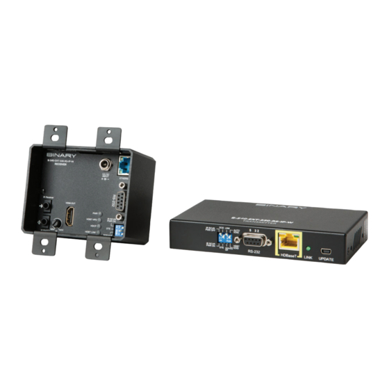
4. DEVICE LAYOUT 4.1. B-540-EXT-330-RS-IPW Transmitter Ethernet Front Back Back of Transmitter Front of Transmitter FIGURE 1: Transmitter Layout A. Thread-locking Power Connector Connect to the included 12V DC, 2A power Supply B. Power LED Lights up blue when the unit has power C. -
Page 6: B-540-Ext-330-Rs-Ipw Receiver
4.2. B-540-EXT-330-RS-IPW Receiver Front Back FIGURE 2: Receiver Layout A. HDMI Out HDMI Output to connect to the HDMI input of a sink(display) B. IR Receiver IR input to connect to IR Receiver or to output of a control system C. -
Page 7: Installation
N. HDBaseT (RJ45 ) To connect to the HDBaseT RJ45 port on transmitter 5. INSTALLATION 5.1. B-540-EXT-330-RS-IPW Transmitter Installation CAUTION: Do not connect power to the device until all other connections are made and the unit is installed. 1. Run category cable from the location of the transmitter to the remote location of the receiver. -
Page 8: Applications
PLAY HDMI Power B-540-EXT-330-RS- IPW Transmitter Ethernet Front Back B-540-EXT-330-RS-IPW Receiver CAT5 Back Front HDMI FIGURE 3 : Application Diagram Note: When a power supply is connected to either the transmitter or receiver, the HDBaseT link sends power to the other unit. Only one unit requires a power supply to be connected. -
Page 9: Ir Control Connections
HDMI Source IR Processor/ Controller PLAY IR Inputs IR Outputs B-540-EXT-330-RS-IPW Transmitter Front Back Front Back B-540-EXT-330-RS-IPW Receiver FIGURE 5: IR Connections Note: Arrow direction indicates signal flow. -
Page 10: Point-To-Point Ir Control - Stereo (3.5Mm) Ir Receiver
6.2.1. Point-to-Point IR Control — Stereo (3.5mm) IR Receiver When using a powered IR receiver, the DIP switch for IR RCVR PWR should be set to ON. In this case a 3.5mm (1/8") stereo jack has to be used to send 9V DC power to the receiver. CAUTION: DO NOT connect a mono cable to this connection as damage may occur. -
Page 11: Ir Flasher Out - Mono (3.5Mm)
Bidirectional RS-232 signals are transmitted between the device transmitter and receiver over the category cable. The transmitter may be connected to a control system, and the receiver may be connected to an RS-232 controllable device. B-540-EXT-330-RS-IPW Transmitter B-540-EXT-330-RS-IPW Receiver Back... -
Page 12: Rs-232 Control (Db-9) Connection
6.3.1. RS-232 Control (DB-9) Connection To eliminate the need to make crossover or null modem cables, the RS-232 pinouts can be configured for DCE or DTE. Set switch 2 to DCE if the connected device is DCE, and to DTE if the connected device is DTE. -
Page 13: Ip Control Connections
When a power supply is connected to either the transmitter or receiver, the HDBaseT link sends power to the other end. Power for the B-540-EXT-330-RS-IPW receiver can be supplied via a remote power source when use of the Latch-Locking Power Jack is not desired. The connection is a 2 conductor... -
Page 14: Optional Remote Power (Receiver Only)
CAUTION: DO NOT connect the power supply to the device until it is completely installed and all connections have been made. Power for the B-540-EXT-330-RS-IPW receiver can be supplied via a remote power source when use of either PoC or the Latch-Locking Power Jack is not desired. The connection is a 2 conductor removable plug located on the rear of the B-540-EXT-330-RS-IPW receiver. -
Page 15: Specifications
7. SPECIFICATIONS Technical Transmitter Receiver HDMI Compliance 4K Ultra HD with Full 3D Support HDCP Compliance Video Bandwidth 10.2 Gbps HDMI over UTP 1080i/720p 24-bit color: 330’ (Cat 5e/6/6a/7) Transmission Full HD 1080p 24-bit color: 330’ (Cat 5e/6/6a/7) Full HD 1080p 36-bit color: 330’ (Cat 5e/6/6a/7) Ultra HD 4K2K@30 Hz (4:4:4:) 230 ft (Cat 5e/6), 330 ft (Cat 6a/7) Ultra HD 4K2K@60 Hz (4:2:0:) 230 ft (Cat 5e/6), 330 ft (Cat 6a/7) Input TMDS Signal... -
Page 16: Support
9. WARRANTY 2-Year Limited Warranty This Binary product has a 2-Year limited warranty. This warranty includes parts and labor repairs on all components found to be defective in material or workmanship under normal conditions of use. This warranty shall not apply to products that have been abused, modified or disassembled.
Need help?
Do you have a question about the B-540-EXT-330-RS-IPW and is the answer not in the manual?
Questions and answers