
Related Manuals for Binary B-900-MOIP-4K


Summary of Contents for Binary B-900-MOIP-4K
- Page 1 MEDIA OVER IP SYSTEM All B-900-MOIP-4K Units INSTALLATION & SETUP GUIDE Source | M (HDMI O...
-
Page 3: Important Safety Instructions
IMPORTANT SAFETY INSTRUCTIONS To reduce the risk of fire or electric shock, read and follow all instructions and warnings in this manual. Keep this manual for future reference. 1. Do not expose to water. 2. Do not remove cover. No user serviceable parts inside. 3. -
Page 4: Getting Started
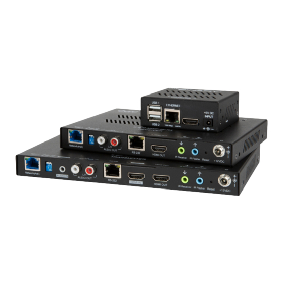
GETTING STARTED To get started, you will need: • 1× per source: MoIP Transmitter B-900-MOIP-4K-TX (or -2AC) • 1× per display: MoIP Receiver B-900-MOIP-4K-RX (or -2AC) • 1× MoIP Controller B-900-MOIP-4K-CTRL • 1× Layer 2 Managed switch • Sources, Displays, HDMI cables and category cabling... - Page 5 MoIP Transmitter B-900-MOIP-4K-TX A. Power Indicator On: Power on | Blink: Booting | Off: Power off B. System Status Light On: Connected to network with source present | Off: Not connected to network | Blinking: Connected to network and o source present C.
- Page 6 MoIP Transmitter B-900-MOIP-4K-TX-2AC A. Power Indicator On: Power on | Blink: Booting | Off: Power off B. System Status Light On: Connected to network with source present | Off: Not connected to network | Blinking: Connected to network and o source present C.
- Page 7 MoIP Receiver B-900-MOIP-4K-RX A. Power Indicator On: Power on | Blink: Booting | Off: Power off B. System Status Light On: Connected to network and not subscribed to transmitter stream | Off: Not connected to network | Blinking: Connected to network and subscribed to transmitter stream C.
- Page 8 MoIP Receiver B-900-MOIP-4K-RX-2AC A. Power Indicator On: Power on | Blink: Booting | Off: Power off B. System Status Light On: Connected to network and not subscribed to transmitter stream | Off: Not connected to network | Blinking: Connected to network and subscribed to transmitter stream C.
-
Page 9: Recommended Network Switches
This section details the networking requirements, recommendations and limitations when configuring a Binary B-900 Series Media over IP system (MoIP) system which can be used to deploy MoIP on any compatible network switch. Also, you will find the simple steps to configure... -
Page 10: Number Of Ports
LAN as MoIP as a best practice. This is not required; however, highly recommended. Number of Ports Given the flexibility and scalability of Binary’s B-900 Series Media over IP system, it is recommended that a switch with more Ethernet ports than needed for the MoIP system be used to allow quick addition of devices in the future. -
Page 11: Multiple Switches
MoIP System Network Setups Single switch MoIP network configurations are supported by Araknis 210 PoE and 310 PoE Series switches. Integrators familiar with the above requirements and the configuration of stackable and cascaded switches with multi-gigabit uplinks will be able to create very large MoIP deployments. - Page 12 have no impact on available bandwidth. The bandwidth requirements of other devices on the network should also be considered. Each MoIP Transmitter will consume 250-850 Mbps (4K) or 150-750 Mbps (1080p) of the available bandwidth. The lowest bandwidth link limitation applies no matter to which switch in the multiple switch setup the transmitter is connected.
-
Page 13: Enable Igmp Snooping
ARAKNIS 210/310 PoE SERIES CONFIGURATION 1. Configure Network Switch Steps below use an Araknis 210 PoE or 310 PoE Series switch as an example 1. Factory default the MoIP switch to be used for all MoIP Components (not necessary for new switches). - Page 14 3. Verify Jumbo Frame SETTINGS > PORTS, then verify Jumbo Frame Choose is set to greater than 8,000 Bytes. The default value is 9216 the maximum is acceptable. 4. Set up the MoIP Controller Claim MoIP controller on OvrC and access the local UI. IMPORTANT: REQUIRED This is...
-
Page 15: Powering Up The System
5. Access Local UI using Remote Access Connect the controller to the MoIP Switch, then use the external power supply to connect to an AC outlet. 1. Once connected, log into the MoIP Controller (username/pasword is binary/binary). You Configure> Account Management. - Page 16 9. Discover MoIP Transmitters and MoIP Receivers Access the local UI of the MoIP controller and click Discover and confirm to activate. The discovery process identifies all transmitters and receivers on the system and displays. Devices will be discovered and assigned a transmitter or receiver number. Transmitter and receiver numbers will correlate directly with the inputs or outputs respectively for control system integration, similar to traditional matrix switchers.
- Page 17 10. Update TX and RX Firmware (if necessary) 1. If a firmware update is required on any of the transmitters and receivers, a banner will appear on the MoIP controller main page. 2. Click UPDATE TX/RX. This will apply the firmware update to any or all devices as required. 3.
- Page 18 If one or more MoIP Transmitters are dedicated to the home theater, then those MoIP Transmitter Audio EDID settings should be configured for Pass-through. d. When using a transmitter with downmixing (B-900-MOIP-4K-TX-2AC), you can configure audio latency (up to 250 milliseconds.
- Page 19 TVs are hung upside down due to bezel logos. 5. When using a receiver with downmixing (B-900-MOIP-4K-RX- 2AC), you can configure dowmixing mode (Auto, 2CH, or Bypass) and...
- Page 20 Note: • The video output resolution can be set to 2160p (4K) at 30Hz or 25Hz or 1080p (2K) at 60Hz or 50Hz. • Since each receiver always outputs 4K 30Hz 4:4:4 8 bit color. 4K HDR will be limited to 8-bit color only;...
- Page 21 Create a Video Wall A video wall can be created with receivers currently discovered by the MoIP Controller. After creating the wall, it will be added to the Receiver list alongside the existing receivers. 4x4, 3x3 and 2x2 video walls can be created out of 16, 9 and 4 receivers. Each receiver can only be a member of a single video wall group.
- Page 22 Set up Control System Integrating MoIP with your chosen control system is very similar to the steps to integrate a matrix switcher. The Binary team has developed custom drivers and worked with control system manufacturers to certify. The following control system drivers, models and documentation are available: Please refer to individual driver support documents for specific features and capabilities.
- Page 23 End User App • Visit Configure -> Client Control App Settings via the controller UI to enable client control outside of a control system. This allows clients to easily change input sources for each video display from their tablet or mobile device. Configure scenes to create common display templates (i.e.
-
Page 24: Two (2) Year Limited Warranty
Two (2) Year Limited Warranty This Binary product has a Two-Year Limited Warranty. This warranty includes parts and labor repairs on all components found to be defective in material or workmanship under normal conditions of use. This warranty shall not apply to products that have been abused, modified or disassembled.
Need help?
Do you have a question about the B-900-MOIP-4K and is the answer not in the manual?
Questions and answers