Table of Contents
Advertisement
Quick Links
Advertisement
Table of Contents

Related Manuals for Edimax OAP900


Summary of Contents for Edimax OAP900
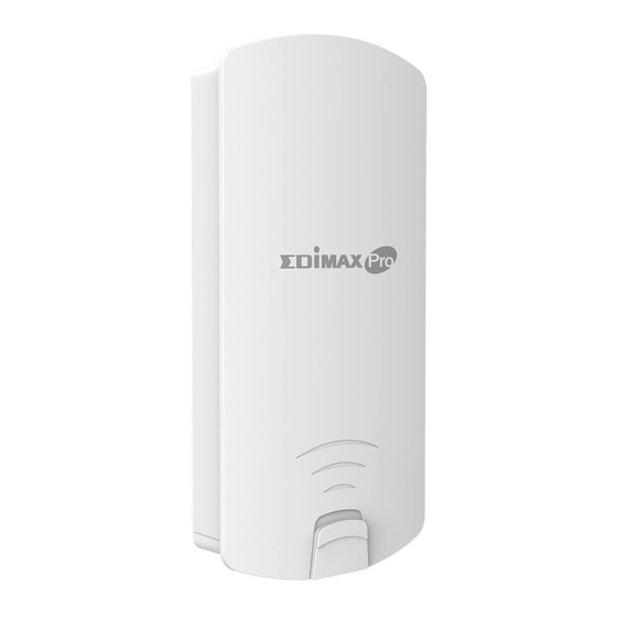
- Page 1 OAP900 User Manual 05-2016 / v1.0...
-
Page 2: Table Of Contents
II. Quick Setup ................... 8 II-1. Passive PoE Injector ......................8 II-2. AP Mode.......................... 10 II-3. Managed AP Mode: Edimax Pro NMS ................14 II-4. Client Bridge Mode ......................18 IV. Browser Based Configuration Interface ..........20 IV-1. Information ........................22 IV-1-1. - Page 3 IV-3-3-4. WDS ......................... 47 IV-3-3-5. Guest Network ......................49 IV-3-4. WPS ..........................51 IV-3-5. RADIUS ..........................53 IV-3-5-1. RADIUS Settings ....................... 54 IV-3-5-2. Internal Server ......................55 IV-3-5-3. RADIUS Accounts ..................... 57 IV-3-6. MAC Filter ........................59 IV-3-7. WMM ..........................61 IV-3-8.
- Page 4 Managed AP mode acts as a “slave” AP within the AP array (controlled by the AP Controller “master”). In Client Bridge mode the OAP900 connects wirelessly to an AP’s SSID while remaining in the same IP address range as that AP – the WAN and LAN are on...
-
Page 5: Product Information
I. Product Information 1. Access Point 7. Ethernet Cable 2. PoE Injector 8. Power Adapter 3. CD 9. Wall Mount Screw Set 4. Quick Installation Guide 10. Pole Mount Set 5. Wall Mount Screw Template 6. Power Cord... -
Page 6: I-2. System Requirements
I-2. System Requirements - Existing cable/DSL modem & router - Computer with web browser for access point configuration I-3. Hardware Overview C Reset D SMA A LAN1 (PoE) IN E PoE Out On/Off LAN1 port with Power over Ethernet (Passive PoE) IN. LAN2 port with Power over Ethernet (Passive PoE) OUT. -
Page 7: I-4. Led Status
I-4. LED Status LED Behavior The access point is on. Blue Power The access point is off. LAN port is connected. Blue LAN 1 & 2 Flashing Activity (transferring and receiving) LAN port is unconnected. Blue Wireless enabled. Wireless Excellent/Good/Medium/Bad for RSSI Signal (Client mode Flashing Strength. -
Page 8: I-6. Mounting
I-6. Mounting The access point includes a mount for wall or pole which requires some assembly. Wall Mount Attach the mount and access point to a wall using the included screws and plugs. - Page 9 Pole Mount Fix the mount and access point to a pole using the included pole mount straps.
-
Page 10: I-7. Safety Information
I-7. Safety Information In order to ensure the safe operation of the device and its users, please read and act in accordance with the following safety instructions. 1. Do not place the access point in or near hot/humid places, such as a kitchen or bathroom. -
Page 11: Ii. Quick Setup
II. Quick Setup The OAP900 Long Range 802.11ac Outdoor Access Point features a range of powerful functions: - 802.11ac high-speed wireless technology - 16 SSIDs for management - SNMP v1/v2c/v3 Your access point can be up and running in just a few minutes. It can function as a standalone access point (AP mode), as part of an AP array (Managed AP mode), or as a client bridge for WISP last-mile services (Client Bridge mode). - Page 12 Use an Ethernet cable to connect the access point’s LAN port to your network: router, access point or switch. If it’s more convenient for initial setup, you can connect a computer directly to the access point’s LAN port instead. Connect the PoE injector to a power source using the included power adapter.
-
Page 13: Ii-2. Ap Mode
II-2. AP Mode Enter the access point’s IP address into the URL bar of a web browser. The default IP is 192.168.2.2. If the AP is connected to a DHCP server, ensure you use the correct address. You will be prompted for a user name and password. Enter the default username “admin”... - Page 14 - LAN IP Address - 5GHz SSID & Security - Administrator Name & Password - Time & Date It is recommended you configure these settings before using the access point. To change the access point’s LAN IP address, go to “Network Settings” > “LAN-side IP Address”...
- Page 15 To configure the security of your access point’s 5GHz wireless network(s), go to “Wireless Settings” > “5GHz 11ac 11an” > “Security”. Select an “Authentication Method” and enter a “Pre-shared Key” or “Encryption Key” depending on your choice, then click “Apply”. If using multiple SSIDs, specify which SSID to configure using the “SSID”...
- Page 16 Complete the “Administrator Name” and “Administrator Password” fields and click “Apply”. To set the correct time for your access point, go to “Management” > “Date and Time Settings”. Set the correct time and time zone for your access point using the drop down menus.
-
Page 17: Ii-3. Managed Ap Mode: Edimax Pro Nms
128 access points with the APC 500 AP controller - reducing costs and facilitating efficient remote AP management. Edimax Pro NMS is simple to setup. An overview of the system is shown below: One AP (access point) is designated as the AP Controller (master) and other connected Edimax Pro APs are automatically designated as Managed APs (slaves). - Page 18 OAP900 as a Managed AP, you can configure the setting manually as below: Ensure all APs including your OAP900 are connected to an Ethernet or PoE switch which is connected to a gateway/router. You can use your router as a DHCP server or you can later configure your AP Controller as a DHCP server.
- Page 19 Ensure you have setup and designated one AP as the AP Controller which will manage all other connected APs (up to 128 depending on model). Connect a computer to the OAP900 via PoE switch using an Ethernet cable. Open a web browser and enter the OAP900’s IP address in the address...
- Page 20 Enter the username & password to login. The default username & password are admin & 1234. You will arrive at the Edimax Pro NMS Dashboard. Go to “Operation Mode” and select “Managed AP Mode” from the drop down menu.
-
Page 21: Ii-4. Client Bridge Mode
II-4. Client Bridge Mode Client Bridge mode enables the OAP900 to wirelessly connect to an AP’s SSID while remaining in the same IP address range as that AP – the WAN and LAN are on the same subnet. This is ideal for last-mile solutions. Settings here are saved as profiles. - Page 22 Click Scan to search for and display available SSIDs and click Select to connect to an available source SSID. Enter the encryption information for the SSID and then click Connect.
-
Page 23: Iv. Browser Based Configuration Interface
Controller AP to configure your Managed AP(s). The browser-based configuration interface enables you to configure the access point’s advanced features. The OAP900 features a range of advanced functions such as MAC filtering, MAC RADIUS authentication, VLAN configurations, up to 16 SSIDs and many more. To access the browser based configuration interface: Connect a computer to your access point using an Ethernet cable. - Page 24 Use the menu across the top and down the left side to navigate. Click “Apply” to save changes and reload the access point, or “Cancel” to cancel changes. Please wait a few seconds for the access point to reload after you “Apply”...
-
Page 25: Iv-1. Information
IV-1. Information Screenshots displayed are examples. The information shown on your screen will vary depending on your configuration. IV-1-1. System Information The “System Information” page displays basic system information about the access point. - Page 26 System Model Displays the model number of the access point. Product Name Displays the product name for reference, which consists of “AP” plus the MAC address. Uptime Displays the total time since the device was turned on. Boot From Displays information for the booted hardware, booted from either USB or internal memory.
- Page 27 Gateway gateway. IP address of DNS (Domain Name Server) DHCP Server IP address of DHCP Server. Wired LAN Port Settings Wired LAN Port Specifies which LAN port. Status Displays the status of the specified LAN port (connected or disconnected). VLAN Mode/ID Displays the VLAN mode (tagged or untagged) and VLAN ID for the specified LAN port.
- Page 28 VLAN Mode/ID Displays the VLAN ID for the specified WDS. See IV-3-1-4. WDS Refresh Click to refresh all information. Client Bridge Mode: Wireless 2.4GHZ (5GHz) / SSID Connection Status Current status of the repeater’s connection. Source SSID Displays the SSID name(s) for the repeater’s source.
-
Page 29: Iv-1-2. Wireless Clients
IV-1-2. Wireless Clients The “Wireless Clients” page displays information about all wireless clients connected to the access point on the 2.4GHz or 5GHz frequency. Refresh time Auto Refresh Time Select a time interval for the client table list to automatically refresh. Manual Refresh Click refresh to manually refresh the client table. - Page 30 Vendor The vendor of the client’s wireless adapter is displayed here.
-
Page 31: Iv-1-3. Wireless Monitor
IV-1-3. Wireless Monitor Wireless Monitor is a tool built into the access point to scan and monitor the surrounding wireless environment. Select a frequency and click “Scan” to display a list of all SSIDs within range along with relevant details for each SSID. Wireless Monitor Site Survey Select which frequency (or both) to scan, and... -
Page 32: Iv-1-4. Dhcp Client Table
IV-1-4. DHCP Client Table The DHCP client table displays information about DHCP clients when DHCP server is enabled. DHCP Client Table IP Address Displays the IP address of listed DHCP client. MAC Address Displays the MAC address of listed DHCP client. -
Page 33: Iv-1-5. Log
IV-1-5. The system log displays system operation information such as up time and connection processes. This information is useful for network administrators. When the log is full, old entries are overwritten. Use the Search function to quickly locate log entries. Save Click to save the log as a file on your local computer. - Page 34 The following information/events are recorded by the log: USB Mount & unmount Wireless Client Connected & disconnected Key exchange success & fail Authentication Authentication fail or successful. Association Success or fail WPS M1 - M8 messages WPS success ...
-
Page 35: Iv-2. Network Settings
IV-2. Network Settings Screenshots displayed are examples. The information shown on your screen will vary depending on your configuration. IV-2-1. LAN-Side IP Address The “LAN-side IP address” page allows you to configure your access point on your Local Area Network (LAN). You can enable the access point to dynamically receive an IP address from your router’s DHCP server or you can specify a static IP address for your access point, as well as configure DNS servers. - Page 36 Default Gateway For DHCP users, select “From DHCP” to get default gateway from your DHCP server or “User-Defined” to enter a gateway manually. For static IP users, the default value is blank. DHCP users can select to get DNS servers’ IP address from DHCP or manually enter a value.
-
Page 37: Iv-2-2. Lan Port
IV-2-2. LAN Port The “LAN Port” page allows you to configure the settings for your access point’s two wired LAN (Ethernet) ports. Wired LAN Port Identifies LAN port number. Enable Enable/disable specified LAN port. Speed & Duplex Select a speed & duplex type for specified LAN port, or use the “Auto”... -
Page 38: Iv-2-3. Vlan
IV-2-3. VLAN The “VLAN” (Virtual Local Area Network) enables you to configure VLAN settings. A VLAN is a local area network which maps workstations virtually instead of physically and allows you to group together or isolate users from each other. VLAN IDs 1 – 4095 are supported. VLAN IDs in the range 1 –... -
Page 39: Iv-3. Wireless Settings
IV-3. Wireless Settings Screenshots displayed are examples. The information shown on your screen will vary depending on your configuration. IV-3-1. Wireless Extender Only available in Client Bridge Mode The wireless extender page displays details about the APs wireless connection in client bridge mode and enables you to connect to a source SSID. - Page 40 Wireless 5GHz Select Click to select an SSID and display a new Create Profile window to enter security information (below). Channel Displays the channel number of listed SSID. SSID Displays the SSID. MAC Address Displays the MAC address of specified SSID. Security Displays the existing security type for listed SSID.
-
Page 41: Iv-3-2. Profile List
IV-3-2. Profile List Only available in Client Bridge Mode Client bridge mode settings are saved as profiles. Profiles can be edited and multiple profiles can be created to switch between profiles easily as required. Select an existing profile and click Edit or Connect. Wireless Create Profile SSID Displays the selected source SSID for this... -
Page 42: Iv-3-3. 5Ghz 11Ac 11An
IV-3-3. 5GHz 11ac 11an The “5GHz 11ac 11an” menu allows you to view and configure information for your access point’s 5GHz wireless network across five categories: Basic, Advanced, Security, WDS & Schedule. IV-3-3-1. Basic The “Basic” screen displays basic settings for your access point’s 5GHz Wi-Fi network (s). - Page 43 access point. Combinations of 802.11a, 802.11n & 802.11ac can be selected. Enable SSID Number Select how many SSIDs to enable for the 5GHz frequency from the drop down menu. A maximum of 16 can be enabled. SSID# Enter the SSID name for the specified SSID (up to 16).
-
Page 44: Iv-3-3-2. Advanced
BSS BasicRate Set Set a Basic Service Set (BSS) rate: this is a series of rates to control communication frames for wireless clients. IV-3-3-2. Advanced These settings are for experienced users only. Please do not change any of the values on this page unless you are already familiar with these functions. - Page 45 Fragment Set the fragment threshold of the wireless Threshold radio. The default value is 2346. Multicast Rate Set the transfer rate for multicast packets or use the “Auto” setting. Tx Power Set the power output of the wireless radio. You may not require 100% output power.
-
Page 46: Iv-3-3-3. Security
IV-3-3-3. Security The access point provides various security options (wireless data encryption). When data is encrypted, information transmitted wirelessly cannot be read by anyone who does not know the correct encryption key. It’s essential to configure wireless security in order to prevent unauthorised access to your network. -
Page 47: Iv-3-3-3-1. No Authentication
Wireless Client Enable or disable wireless client isolation. Isolation Wireless client isolation prevents clients connected to the access point from communicating with each other and improves security. Typically, this function is useful for corporate environments or public hot spots and can prevent brute force attacks on clients’ usernames and passwords. -
Page 48: Iv-3-3-3-3. Ieee802.1X/Eap
the default key. Encryption Key 1 – Enter your encryption key/password according to the format you selected above. IV-3-3-3-3. IEEE802.1x/EAP Key Length Select 64-bit or 128-bit. 128-bit is more secure than 64-bit and is recommended. IV-3-3-3-4. WPA-PSK WPA-PSK is a secure wireless encryption type with strong data protection and user authentication, utilizing 128-bit encryption keys. -
Page 49: Iv-3-3-3-6. Additional Authentication
Interval minutes. WPA-EAP must be disabled to use MAC-RADIUS authentication. IV-3-3-3-6. Additional Authentication Additional wireless authentication methods can also be used: WPS must be disabled to use additional authentication. See IV-3-4. for WPS settings. MAC Address Filter Restrict wireless clients access based on MAC address specified in the MAC filter table. -
Page 50: Iv-3-3-4. Wds
IV-3-3-4. WDS Wireless Distribution System (WDS) can bridge/repeat access points together in an extended network. WDS settings can be configured as shown below. When using WDS, configure the IP address of each access point to be in the same subnet and ensure there is only one active DHCP server among connected access points, preferably on the WAN side. - Page 51 5GHz WDS Mode WDS Functionality Select “WDS with AP” to use WDS with access point or “WDS Dedicated Mode” to use WDS and also block communication with regular wireless clients. When WDS is used, each access point should be configured with corresponding MAC addresses, wireless channel and wireless encryption method.
-
Page 52: Iv-3-3-5. Guest Network
IV-3-3-5. Guest Network You can setup an additional “Guest” Wi-Fi network so guest users can enjoy Wi-Fi connectivity without accessing your primary networks. Enable a guest network and then configure the settings. Guest Network 5GHz SSID Displays the guest network name (SSID). Guest Network Enable or disable the guest network. - Page 53 the Deny or Allow rule specified above and check the box for each IP address to be filtered.
-
Page 54: Iv-3-4. Wps
IV-3-4. WPS Wi-Fi Protected Setup is a simple way to establish connections between WPS compatible devices. WPS can be activated on compatible devices by pushing a WPS button on the device or from within the device’s firmware/configuration interface (known as PBC or “Push Button Configuration”). When WPS is activated in the correct manner and at the correct time for two compatible devices, they will automatically connect. - Page 55 IV-3-3-3-3 & IV.3-5). Product PIN Displays the WPS PIN code of the device, used for PIN code WPS. You will be required to enter this PIN code into another WPS device for PIN code WPS. Click “Generate PIN” to generate a new WPS PIN code.
-
Page 56: Iv-3-5. Radius
IV-3-5. RADIUS The RADIUS menu allows you to configure the access point’s external RADIUS server settings. A RADIUS server provides user-based authentication to improve security and offer wireless client control – users can be authenticated before gaining access to a network. The access point can utilize both a primary and secondary (backup) external RADIUS server. -
Page 57: Iv-3-5-1. Radius Settings
IV-3-5-1. RADIUS Settings Configure the RADIUS server settings for 5GHz. You can use an internal or external RADIUS server. RADIUS Type Select “Internal” to use the access point’s built-in RADIUS server or “external” to use an external RADIUS server. RADIUS Server Enter the RADIUS server host IP address. -
Page 58: Iv-3-5-2. Internal Server
the RADIUS server. Value must be between 1 – 65535. IV-3-5-2. Internal Server The access point features a built-in RADIUS server which can be configured as shown below used when “Internal” is selected for “RADIUS Type” in the “Wireless Settings” “RADIUS” “RADIUS Settings” menu. ... - Page 59 certificate. Shared Secret Enter a shared secret/password for use between the internal RADIUS server and RADIUS client. The shared secret should be 1 – 99 characters in length. This should match the “MAC-RADIUS” password used in IV-3-1-3-6 or IV-3-2-3. Session Timeout Set a duration of session timeout in seconds between 0 –...
-
Page 60: Iv-3-5-3. Radius Accounts
IV-3-5-3. RADIUS Accounts The internal RADIUS server can authenticate up to 256 user accounts. The “RADIUS Accounts” page allows you to configure and manage users. - Page 61 User Name Enter the user names here, separated by commas. Click “Add” to add the user to the user registration list. Reset Clear text from the user name box. Select Check the box to select a user. User Name Displays the user name. Password Displays if specified user name has a password (configured) or not (not configured).
-
Page 62: Iv-3-6. Mac Filter
IV-3-6. MAC Filter Mac filtering is a security feature that can help to prevent unauthorized users from connecting to your access point. This function allows you to define a list of network devices permitted to connect to the access point. Devices are each identified by their unique MAC address. - Page 63 commas, e.g. ‘aa-bb-cc-dd-ee-ff,aa-bb-cc-dd-ee-gg’ Click “Add” to add the MAC address to the MAC address filtering table. Reset Clear all fields. MAC address entries will be listed in the “MAC Address Filtering Table”. Select an entry using the “Select” checkbox. Select Delete selected or all entries from the table.
-
Page 64: Iv-3-7. Wmm
IV-3-7. WMM Wi-Fi Multimedia (WMM) is a Wi-Fi Alliance interoperability certification based on the IEEE 802.11e standard, which provides Quality of Service (QoS) features to IEE 802.11 networks. WMM prioritizes traffic according to four categories: background, best effort, video and voice. Configuring WMM consists of adjusting parameters on queues for different categories of wireless traffic. - Page 65 CWMin Minimum Contention Window (milliseconds): This value is input to the initial random backoff wait time algorithm for retry of a data frame transmission. The backoff wait time will be generated between 0 and this value. If the frame is not sent, the random backoff value is doubled until the value reaches the number defined by CWMax (below).
-
Page 66: Iv-3-8. Traffic Shaping
IV-3-8. Traffic Shaping The traffic shaping function allows you to regulate network data transfer to ensure or prioritize performance by limiting uplink and downlink speeds according to SSID. Enable Unlimited: 0 Check/uncheck to enable or disable unlimited Mbps transfer speed. Downlink/Uplink The maximum down/uplink capacity in Mbps. -
Page 67: Iv-3-9. Antenna
IV-3-9. Antenna The access point features a built-in internal antenna and can also be used with external antennas. Specify which type of antenna you are using. -
Page 68: Iv-4. Management
IV-4. Management Screenshots displayed are examples. The information shown on your screen will vary depending on your configuration. IV-4-1. Admin You can change the password used to login to the browser-based configuration interface here. It is advised to do so for security purposes. If you change the administrator password, please make a note of the new password. - Page 69 Account to Manage This Device Administrator Set the access point’s administrator name. Name This is used to log in to the browser based configuration interface and must be between 4-16 alphanumeric characters (case sensitive). Administrator Set the access point’s administrator password. Password This is used to log in to the browser based configuration interface and must be between...
- Page 70 Product Name Edit the product name according to your preference consisting of 1-32 alphanumeric characters. This name is used for reference purposes. HTTP Port Specify HTTP port number. HTTPS Port Specify HTTPS port number. Management Check/uncheck the boxes to enable/disable Protocol specified management interfaces (see below).
-
Page 71: Iv-4-2. Date And Time
IV-4-2. Date and Time You can configure the time zone settings of your access point here. The date and time of the device can be configured manually or can be synchronized with a time server. Date and Time Settings Local Time Set the access point’s date and time manually using the drop down menus. - Page 72 Server Name Enter the host name or IP address of the time server if you wish. Update Interval Specify a frequency (in hours) for the access point to update/synchronize with the NTP server. Time Zone Time Zone Select the time zone of your country/ region. If your country/region is not listed, please select another country/region whose time zone is the same as yours.
-
Page 73: Iv-4-3. Syslog Server
IV-4-3. Syslog Server The system log can be sent to a server or to attached USB storage. Syslog Server Settings Transfer Logs Check/uncheck the box to enable/disable the use of a syslog server, and enter a host name, domain or IP address for the server, consisting of up to 128 alphanumeric characters. -
Page 74: Iv-4-4. Ping Test
IV-4-4. Ping Test The access point includes a built-in ping test function. Ping is a computer network administration utility used to test whether a particular host is reachable across an IP network and to measure the round-trip time for sent messages. Destination Address Enter the address of the host. -
Page 75: Iv-5. Advanced
IV-5. Advanced Screenshots displayed are examples. The information shown on your screen will vary depending on your configuration. IV-5-1. LED Settings The access point’s LEDs can be manually enabled or disabled according to your preference. Power LED Select on or off. 5GHz Signal Strength Select on or off. -
Page 76: Iv-5-2. Update Firmware
Updated firmware versions often offer increased performance and security, as well as bug fixes. You can download the latest firmware from the Edimax website. Do not switch off or disconnect the access point during a firmware upgrade, as this could damage the device. -
Page 77: Iv-5-3. Save/Restore Settings
IV-5-3. Save/Restore Settings The access point’s “Save/Restore Settings” page enables you to save/backup the access point’s current settings as a file to your local computer or a USB device attached to the access point, and restore the access point to previously saved settings. - Page 78 Restore Settings from PC Restore Settings Click the browse button to find a previously saved settings file on your computer, then click “Restore” to replace your current settings. If your settings file is encrypted with a password, check the “Open file with password”...
-
Page 79: Iv-5-4. Factory Default
IV-5-4. Factory Default If the access point malfunctions or is not responding, then it is recommended that you reboot the device (see IV-5.5) or reset the device back to its factory default settings. You can reset the access point back to its default settings using this feature if the location of the access point is not convenient to access the reset button. -
Page 80: Iv-5-5. Reboot
IV-5-5. Reboot If the access point malfunctions or is not responding, then it is recommended that you reboot the device or reset the access point back to its factory default settings (see IV-5-4). You can reboot the access point remotely using this feature. -
Page 81: Iv-6. Operation Mode
Managed AP mode acts as a “slave” AP within the AP array (controlled by the AP Controller “master”). In Client Bridge mode the OAP900 connects wirelessly to an AP’s SSID while remaining in the same IP address range as that AP – the WAN and LAN are on the same subnet. -
Page 82: Appendix
V. Appendix V-1. Configuring your IP address The access point uses the default IP address 192.168.2.2. In order to access the browser based configuration interface, you need to modify the IP address of your computer to be in the same IP address subnet e.g. 192.168.2.x (x = 3 – 254). -
Page 83: V-1-1. Windows Xp
V-1-1. Windows XP Click the “Start” button (it should be located in the lower-left corner of your computer), then click “Control Panel”. Double-click the “Network and Internet Connections” icon, click “Network Connections”, and then double-click “Local Area Connection”. The “Local Area Connection Status” window will then appear, click “Properties”. -
Page 85: V-1-2. Windows Vista
V-1-2. Windows Vista Click the “Start” button (it should be located in the lower-left corner of your computer), then click “Control Panel”. Click “View Network Status and Tasks”, then click “Manage Network Connections”. Right-click “Local Area Network”, then select “Properties”. The “Local Area Connection Properties” window will then appear, select “Internet Protocol Version 4 (TCP / IPv4)”, and then click “Properties”. -
Page 87: V-1-3. Windows 7
V-1-3. Windows 7 Click the “Start” button (it should be located in the lower-left corner of your computer), then click “Control Panel”. Under “Network and Internet” click “View network status and tasks”. Click “Local Area Connection”. - Page 88 Click “Properties”.
- Page 89 Select “Internet Protocol Version 4 (TCP/IPv4) and then click “Properties”. Select “Use the following IP address”, then input the following values: IP address: 192.168.2.10 Subnet Mask: 255.255.255.0 Click ‘OK’ when finished.
-
Page 91: V-1-4. Windows 8
V-1-4. Windows 8 From the Windows 8 Start screen, you need to switch to desktop mode. Move your curser to the bottom left of the screen and click. In desktop mode, click the File Explorer icon in the bottom left of the screen, as shown below. - Page 92 Right click “Network” and then select “Properties”. In the window that opens, select “Change adapter settings” from the left side.
- Page 93 Choose your connection and right click, then select “Properties”. Select “Internet Protocol Version 4 (TCP/IPv4) and then click “Properties”.
- Page 94 Select “Use the following IP address”, then input the following values: IP address: 192.168.2.10 Subnet Mask: 255.255.255.0 Click ‘OK’ when finished.
-
Page 95: V-1-5. Mac
V-1-5. Mac Have your Macintosh computer operate as usual, and click on “System Preferences” In System Preferences, click on “Network”. Click on “Ethernet” in the left panel. Open the drop-down menu labeled “Configure IPv4” and select “Manually”. - Page 96 Enter the IP address 192.168.2.10 and subnet mask 255.255.255.0. Click on “Apply” to save the changes.
- Page 97 COPYRIGHT Copyright Edimax Technology Co., Ltd. all rights reserved. No part of this publication may be reproduced, transmitted, transcribed, stored in a retrieval system, or translated into any language or computer language, in any form or by any means, electronic, mechanical, magnetic, optical, chemical, manual or otherwise, without the prior written permission from Edimax Technology Co., Ltd.
-
Page 98: Federal Communication Commission Interference Statement
Federal Communication Commission Interference Statement This equipment has been tested and found to comply with the limits for a Class B digital device, pursuant to Part 15 of FCC Rules. These limits are designed to provide reasonable protection against harmful interference in a residential installation. - Page 99 EU Declaration of Conformity English: This equipment is in compliance with the essential requirements and other relevant provisions of Directive 1995/5/EC, 2009/125/EC, 2006/95/EC, 2011/65/EC. Français: Cet équipement est conforme aux exigences essentielles et autres dispositions de la directive 1995/5/CE, 2009/125/CE, 2006/95/CE, 2011/65/CE. Čeština: Toto zařízení...
-
Page 100: Declaration Of Conformity
Declaration of Conformity We, Edimax Technology Co., Ltd., declare under our sole responsibility, that the equipment described below complies with the requirements of the European R&TTE directives. Equipment: Outdoor Access Point Model No.: OAP900 The following European standards for essential requirements have been followed:... - Page 101 Notice According to GNU General Public License Version 2 This product includes software that is subject to the GNU General Public License version 2. The program is free software and distributed without any warranty of the author. We offer, valid for at least three years, to give you, for a charge no more than the costs of physically performing source distribution, a complete machine-readable copy of the corresponding source code.
- Page 102 work based on the Program (independent of having been made by running the Program). Whether that is true depends on what the Program does. 1. You may copy and distribute verbatim copies of the Program’s source code as you receive it, in any medium, provided that you conspicuously and appropriately publish on each copy an appropriate copyright notice and disclaimer of warranty;...
- Page 103 under this License. However, parties who have received copies, or rights, from you under this License will not have their licenses terminated so long as such parties remain in full compliance. 5. You are not required to accept this License, since you have not signed it. However, nothing else grants you permission to modify or distribute the Program or its derivative works.
Need help?
Do you have a question about the OAP900 and is the answer not in the manual?
Questions and answers