
Related Manuals for Mitsubishi D700 VFD


Summary of Contents for Mitsubishi D700 VFD
- Page 1 MACHMOTION Mitsubishi D700 VFD Installation Guide 3/12/2012 Everything you need to know to set up your Mitsubishi VFD. MachMotion Version 1.0.2...
- Page 2 P a g e Copyright © 2011, MachMotion.com All rights reserved. MachMotion www.machmotion.com 14518 County Road 7240, Newburg, MO 65550 (573) 368-7399 • Fax (573) 341-2672...
-
Page 3: Table Of Contents
P a g e Overview __________________________________________________________________________ 4 Wiring ____________________________________________________________________________ 5 Control Cable ____________________________________________________________________________ 5 Enable Circuit ____________________________________________________________________________ 6 Spindle Motor ____________________________________________________________________________ 7 Brake Resistor ____________________________________________________________________________ 8 Programming ______________________________________________________________________ 9 VFD Setup ________________________________________________________________________ 10 Standard Setup __________________________________________________________________________ 10 Auto Tuning _____________________________________________________________________________ 11 Brake Resistor ___________________________________________________________________________ 11 Mach3 Setup ______________________________________________________________________ 12 Turning on Your Spindle _____________________________________________________________ 15... -
Page 4: Overview
P a g e Overview This installation manual is designed for Mitsubishi Variable Frequency Drives (VFDs) purchased from MachMotion. It was written to interface VFDs with the Apollo I Breakout Board. It provides all the information from wiring your VFD to troubleshooting it. Much of the wiring and many of the settings should already be configured correctly for your spindle motor. -
Page 5: Wiring
Control Cable The VFD control cable is the Cat5 cable that runs from the breakout board to the Mitsubishi VFD. From the factory it is already wired correctly to the VFD. Plug the cable into the RJ45 connector labeled Spindle Control on the IO6 Breakout Board. -
Page 6: Enable Circuit
P a g e Enable Circuit To set up your VFD correctly, you only want power supplied to it while your control is enabled. Use the 24V enable signal (24-EN) from the breakout board, a 24V relay, and a contactor as shown below. If you purchased a drive enclosure, your enable circuit is already set up. -
Page 7: Spindle Motor
P a g e Spindle Motor Connect your spindle motor to the terminals labeled U, V, and W as shown below. If your spindle moves the wrong direction when you turn it on, just swap any two of the spindle motor wires. Figure 3 Spindle Motor... -
Page 8: Brake Resistor
P a g e Brake Resistor If you want a brake on your spindle, you will need a brake resistor. Use the table below to locate the correct resistor size. You can order them directly from Mitsubishi. Motor (Hp) Resistance (Ohms) -
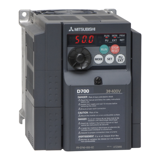
Page 9: Programming
P a g e Programming To setup your VFD, you will have to learn how to program it. The VFD user interface consists of a small screen, 5 buttons, a few status LEDs, and a scroll wheel as shown below. Figure 5 VFD User Interface To change any settings you must enter PU mode. -
Page 10: Vfd Setup
10 | P a g e VFD Setup To setup your VFD you will need to know your spindle motor’s frequency. It is also helpful to know the maximum current that your spindle motor should ever draw. You should be able to find both values on the motor’s nameplate. -
Page 11: Auto Tuning
Motor Capacity Rated Motor kW 0.1-7.5kW If you do not have a Mitsubishi spindle motor, just set parameter 71 to 13. Otherwise enter the motor code into the parameter. To auto tune your VFD, follow the instructions below. 1. Set parameter 96 to 11. - Page 12 12 | P a g e Test Run You can test your spindle motor directly from your VFD. Follow the sequence below. 1. Press PU/EXT to put the VFD into PU mode (make sure the PU LED is on). 2. Press the Mode button until the MON LED turns on. 3.
-
Page 13: Mach3 Setup
13 | P a g e Mach3 Setup With your spindle wired and programmed, it is time to set up Mach3. You must enter in your maximum RPM for the spindle motor so Mach3 knows how to scale the analog voltage output. If you have different gears, you can set up multiple maximum speeds. - Page 14 14 | P a g e You can also change pulleys by using M41-M45. The macros can be used to just change pulleys in Mach3, or you could use them to automatically change gears on your machine. Outputs 12-16 are configured to shift between gears 1 and 5.
-
Page 15: Turning On Your Spindle
15 | P a g e Turning on Your Spindle To turn on your spindle, begin by setting up your spindle speed. Navigate to Prog Run and click on the Spindle S: user input. Enter your speed and press Send as shown in Figure 8. Spindle Speed Press Send Figure 8 Setting up Spindle Speed... - Page 16 16 | P a g e Control the spindle by pressing the FWD and REV buttons. The button will turn red when you press it once. Pressing the button again turns the spindle back off. Figure 10 Spindle Buttons Note: If you don’t have the MachMotion screen set, turn on the spindle by pressing the button Spindle CW F5. When the button is flashing, the spindle should be on.
-
Page 17: Calibrating Your Spindle
17 | P a g e Calibrating Your Spindle For most systems you can completely skip this section. If your IO6 Breakout Board is not outputting the correct analog voltage, you can calibrate your spindle by using the procedure below. There are two different methods to use depending on if you know the spindle speed or not. -
Page 18: With Spindle Feedback
18 | P a g e With Spindle Feedback If you have spindle feedback or a tachometer, you can use the shorter method to calibrate your spindle. Simply find the values shown below. Current Velocity Use the velocity value found above from the Motor Tuning and Setup window. Commanded RPM Enter in a spindle speed as shown above. - Page 19 19 | P a g e Figure 14 Max Pulley Speed Your current pulley will be selected. Your Max Speed value is your pulley max needed for the spindle calibration. Max VFD Hz The maximum motor frequency is your Max VFD Hz (assuming your VFD is set up as shown above). Commanded RPM Enter in a spindle speed as shown above.
-
Page 20: Trouble Shooting
20 | P a g e Trouble Shooting If your spindle is not turning on, follow the procedure below. 1. Check the REV and FWD LEDs on the Apollo I Breakout Board. a. Neither REV nor FWD ever come on: i. -
Page 21: Alarm List
21 | P a g e Alarm List If your VFD has an alarm, use the lists below to figure out what to do. - Page 22 22 | P a g e...
-
Page 23: Warranty Information
When a product or part is exchanged, any replacement item becomes your property and the replaced item becomes MachMotion’s property. Congratulations on completing the Mitsubishi VFD Installation Guide. We hope that you have found this manual very helpful. Please let us know if you have any questions.
Need help?
Do you have a question about the D700 VFD and is the answer not in the manual?
Questions and answers