Table of Contents
Advertisement
Quick Links
Download this manual
See also:
User Manual
JY997D29801B
Side
B
Side
Side
A
B
JAPANESE
ENGLISH
FX
-64CCL
3U
INSTALLATION MANUAL
Manual Number
JY997D29801
Revision
B
Date
June 2008
This manual describes the part names, dimensions, and specifications of the
product. Before use, read this manual and manuals of relevant products fully to
acquire proficiency in handling and operating the product. Make sure to learn all
the product information, safety information, and precautions.
And, store this manual in a safe place so that you can take it out and read it
whenever necessary. Always forward it to the end user.
Registration
The company name and the product name to be described in this manual are
the registered trademarks or trademarks of each company.
Effective June 2008
Specifications are subject to change without notice.
©
2008 Mitsubishi Electric Corporation
Safety Precaution
(Read these precautions before use.)
This manual classifies the safety precautions into two categories:
and
.
Indicates that incorrect handling may cause hazardous
conditions, resulting in death or severe injury.
Indicates that incorrect handling may cause hazardous
conditions, resulting in medium or slight personal injury
or physical damage.
Depending on circumstances, procedures indicated by
cause severe injury.
It is important to follow all precautions for personal safety.
Associated Manuals
Manual name
Manual No.
Description
FX
Series
JY997D31301
Explains the FX
Series PLC
3G
3G
User's Manual
MODEL CODE:
specifications for I/O, wiring,
- Hardware Edition
09R521
installation, and maintenance.
FX
Series
JY997D16501
Explains the FX
Series PLC
3U
3U
User's Manual
MODEL CODE:
specifications for I/O, wiring,
- Hardware Edition
09R516
installation, and maintenance.
FX
Series
JY997D28701
Explains the FX
Series PLC
3UC
3UC
User's Manual
MODEL CODE:
specifications for I/O, wiring,
- Hardware Edition
09R519
installation, and maintenance.
FX
3G
/FX
3U
/FX
3UC
Series
JY997D16601
Describes PLC programming for
Programming Manual
MODEL CODE:
basic/applied instructions and
- Basic & Applied
09R517
devices.
Instruction Edition
JY997D30401
FX
-64CCL
Describes FX
-64CCL type
3U
3U
MODEL CODE:
User's Manual
CC-Link interface block details.
09R718
Manuals for the FX
PLC will be available in September 2008 or later.
3G
How to obtain manuals
For product manuals or documents, contact the Mitsubishi Electric dealer from
whom you purchased your product.
Certification of UL, cUL standards
FX
-64CCL units comply with the UL standards (UL, cUL).
3U
UL, cUL File Number: E95239
Regarding the standards that comply with the main unit, please refer to either
the FX series product catalog or consult with your nearest Mitsubishi product
provider.
Compliance with EC directive (CE Marking)
This note does not guarantee that an entire mechanical module produced in
accordance with the contents of this note will comply with the following standards.
Compliance to EMC directive and LVD directive for the entire mechanical module
should be checked by the user / manufacturer. For more information please consult
with your nearest Mitsubishi product provider.
Regarding the standards that comply with the main unit, please refer to either the FX
series product catalog or consult with your nearest Mitsubishi product provider.
Requirement for Compliance with EMC directive
The following products have shown compliance through direct testing (of the identified
standards below) and design analysis (through the creation of a technical construction
file) to the European Directive for Electromagnetic Compatibility (89/336/EEC) when
used as directed by the appropriate documentation.
Type:
Programmable Controller (Open Type Equipment)
Models:
MELSEC FX
series manufactured
3U
from March 1st, 2008
FX
-64CCL
3U
Standard
Remark
EN61131-2:2003
Compliance with all relevant aspects of the standard.
Programmable controllers
EMI
- Equipment
• Radiated Emissions
r e q u i r e m e n t s a n d
• Conducted Emissions
tests
EMS
• Radiated electromagnetic field
• Fast Transient burst
• Electrostatic discharge
• High-energy surge
• Voltage drops and interruptions
• Conducted RF
• Power frequency magnetic field
Caution for EC Directive
• Installation in Enclosure
Programmable logic controllers are open-type devices that must be installed
and used within conductive control cabinets. Please use the programmable
logic controller while installed within a conductive shielded control cabinet.
Please secure the cabinet door to the control cabinet (for conduction). Installa-
tion within a control cabinet greatly affects the safety of the system and aids in
shielding noise from the programmable logic controller.
• Control cabinet
- The control cabinet must be conductive.
- Ground the control cabinet with the thickest possible grounding cable.
- To ensure that there is electric contact between the control cabinet and its door,
may also
connect the cabinet and its doors with thick wires.
- In order to suppress the leakage of radio waves, the control cabinet structure
must have minimal openings. Also, wrap the cable holes with a shielding cover
or other shielding devices.
- The gap between the control cabinet and its door must be as small as possible
by attaching EMI gaskets between them.
Shielding cover
Shielded cable
EMI gasket
Wires*
* These wires are used to improve the conductivity between the door and control
cabinet.
• Configuration example inside control cabinet
L N
Power
cable
24V DC power
Ground
supply
cable
24+ 24-
Main unit
FX
-64CCL
3U
DA DB
DG
SLD
CC-Link dedicated cable
Cable clamp
(AD75CK,
MITSUBISHI)
Ground
cable
Conductive control cabinet
• Wiring simplified diagram
Termi-
Master
Other
nating
unit
station
FX
-64CCL
3U
resistor
(Blue)
DA
DA
(white)
DB
DB
(yellow)
DG
DG
CC-Link
CC-Link
SLD
SLD
Dedicated
Dedicated
FG
Cable
Cable
1. Introduction
The CC-Link interface block FX
-64CCL (hereinafter called 64CCL) is a special
3U
function block to connect the FX
/FX
/FX
Series programmable logic controller
3G
3U
3UC
to a CC-Link network.
The 64CCL works as an intelligent device station on a CC-Link network.
Only one 64CCL unit can be connected to a single programmable logic controller main
unit.
→ For system configuration, refer to the FX
-64CCL User's Manual.
3U
1.1 Major Features of the FX
-64CCL
3U
1) Compatible with CC-Link Ver. 2.00 and Ver. 1.10
The 64CCL is compatible with CC-Link Ver. 2.00, and enables expanded cyclic
transmission to facilitate the handling of applications requiring multiple data
processing.
In addition to Ver. 2.00, Ver. 1.10 is also supported with the 64CCL.
1.2 Incorporated Items
Check to ensure the following product and items are included in the package:
Product
Manual
Special Unit/Block
Dust proof
protection sheet
No. label
This
Manual
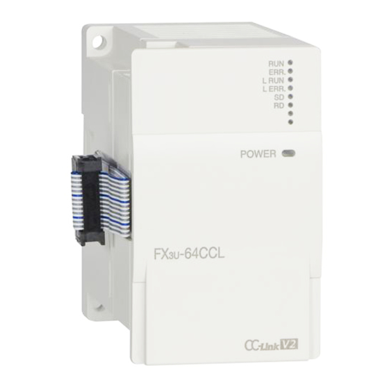
1.3 External Dimensions and Part Names
Without top cover
2-φ4.5 mounting holes
[1]
[2]
[3]
[4]
[5]
[8]
RUN
ERR.
L
RUN
L
ERR.
SD
RD
POWER
[6]
STATION
NO.
COM
SETTING
FX
-64CCL
3U
[7]
4(0.16")
9(0.36")
[13]
[12]
55(2.17")
87(3.43")
Unit: mm (inches)
MASS (Weight): 0.3kg (0.66lbs)
[1] Extension cable
[2] Direct mounting hole: 2 holes of
4.5 (0.18") (mounting screw: M4 screw)
[3] POWER LED (green)
[4] Status LEDs
[5] Name plate
[6] DIN rail mounting groove (DIN rail: DIN46277, 35mm (1.38") width)
[7] DIN rail mounting hook
[8] Power supply terminal block
[9] Extension connector
[10] CC-Link connection terminal block
[11] Number of occupied stations and expanded cyclic setting switch
[12] Transmission rate setting switch
[13] Station number setting switch
1.4 Power and status LEDs
Termi-
LED
nating
Color Status
display
resistor
DA
Power is not being supplied from the external power
OFF
DB
supply (24V DC).
POWER Green
DG
Power is being supplied from the external power
ON
SLD
supply (24V DC).
FG
OFF
64CCL has failed.
RUN
Green
ON
Under 64CCL normal operation.
OFF
No errors.
ERR.
Red
Error in the settings, error in the parameter details,
ON
error with the communication, errors with the H/W.
OFF
Offline.
L RUN
Green
ON
Data link is being executed.
OFF
No communication error.
The switch setting was changed after start.
Flicker
There is no terminating resistor.
L ERR.
Red
Influence from noise.
There is a data linking error.
ON
There is a setting error.
OFF
Data is not being sent.
SD
Green
ON
Data is being sent.
OFF
Data is not being received.
RD
Green
1
ON
Data is being received.
1.5 Terminal layout
Power supply
terminal block
[9]
CC-Link connection
10
1
X
X
terminal block
B RATE STATION
[10]
• Terminal screw and terminal block mounting screw size, and tightening torque
[11]
Power supply terminal block, CC-Link connection terminal block:
M3 screw, 42 to 58 N
•
cm
CC-Link connection terminal block mounting screw (black):
M3.5 screw, 66 to 91 N
•
cm
CC-Link connection terminal block can be detached or attached. Make sure to cut
off all phases of the power supply externally.
For details on the wiring and the types of connection cables needed to connect to
the terminal blocks shown in the figure above, refer to the following manual.
→ Refer to the FX
1.6 Switch setting
With regard to the switch setting for station number, transmission rate, hardware
test, number of occupied stations and expanded cyclic transmission, the switch
settings become valid after 64CCL startup.
If the switch settings are changed after 64CCL startup, the L ERR. LED will flicker.
To change the switch setting, power OFF the 64CCL once, and power it ON again.
For details on the switch setting, refer to the following manual.
→ Refer to the FX
1.6.1
Station number setting
Setting items
Range
× 10
0 to 6
1 to 64
0, 65 to 99 is the setting error.
× 1
0 to 9
Description
3U
-64CCL User's Manual.
3U
-64CCL User's Manual.
Description
Advertisement
Table of Contents

Subscribe to Our Youtube Channel
Related Manuals for Mitsubishi FX3U-64CCL


Summary of Contents for Mitsubishi FX3U-64CCL
- Page 1 0 to 9 UL, cUL File Number: E95239 MITSUBISHI) Ground Regarding the standards that comply with the main unit, please refer to either cable the FX series product catalog or consult with your nearest Mitsubishi product Conductive control cabinet provider.
- Page 2 PS1:1ms. Mitsubishi will not be held liable for damage caused by factors found not to be status changes (status control) to an operating PLC, thoroughly read the manual or impacts, or expose it to high temperature, condensation, or rain and wind.
- Page 3 (status control) to an operating PLC, thoroughly read the manual Mitsubishi will not be held liable for damage caused by factors found not to be or impacts, or expose it to high temperature, condensation, or rain and wind.
Need help?
Do you have a question about the FX3U-64CCL and is the answer not in the manual?
Questions and answers