Table of Contents
Advertisement
Advertisement
Chapters
Table of Contents

Related Manuals for Potterton HE Plus


Summary of Contents for Potterton HE Plus
- Page 1 Installation & Service Instructions Promax System HE Plus Range These instructions include the Benchmark Commissioning Checklist and should be left with the user for safe keeping. © Baxi Heating UK Ltd 2007 Supplied By www.heating spares.co Tel. 0161 620 6677...
- Page 2 Natural Gas Building Regulations and the Benchmark Commissioning Checklist Potterton Promax System 12 HE Plus G.C.N 41 591 90 Building Regulations (England & Wales) require notification of Potterton Promax System 15 HE Plus the installation of a heating appliance to the relevant Local G.C.N...
- Page 3 Installer Notification Guidelines Choose Building Regulations Notification Route Competent Person's Building Control Self Certification Scheme Contact your relevant Local Install and Commission this Authority Building Control appliance to manufacturer's (LABC) who will arrange instructions an inspection or contact a government approved inspector Complete the Benchmark Checklist...
-
Page 4: Systems
Legislation IMPORTANT - Installation, Commissioning, Service & Repair This company declare that no substances harmful to health are contained in the appliance or used during appliance This appliance must be installed in accordance with the manufacturer’s instructions and manufacture. the regulations in force. Read the instructions fully before installing or using the appliance. - Page 5 Safe Manual Handling General The following advice should be adhered to, from when first handling the boiler to the final stages of installation, and also during maintenance. Most injuries as a result of inappropriate handling and lifting are to the back, but all other parts of the body are vulnerable, particularly shoulders, arms and hands. Health &...
-
Page 6: Table Of Contents
CONTENTS Section Page Introduction General Layout Appliance Operation Technical Data Dimensions and Fixings System Details Site Requirements Flue Options Plume Displacement 10.0 Installation 11.0 Commissioning 12.0 Completion 13.0 Servicing 14.0 Changing Components 15.0 Combustion Check 16.0 Electrical 17.0 Short Parts List 18.0 Fault Finding Benchmark Checklist... -
Page 7: Introduction
1.0 Introduction Description 1. The Potterton Promax System HE Plus is a fully automatic gas fired wall mounted condensing system boiler. It is room sealed and fan assisted. Case Front Panel 2. The boiler is set to give a maximum output of :-... -
Page 8: General Layout
2.0 General Layout Layout Expansion Vessel Automatic Air Vent Circulation Pump Drain Off Point Pressure Relief Valve Selector Switch Central Heating System Pressure Gauge Control Box Gas Valve Condensate Trap Flame Sensing Electrode Spark Electrode Primary Heat Exchanger Fan Assembly On/Off/Reset Selector Switch Central Heating Temperature Control Calibration Control... -
Page 9: Appliance Operation
3.0 Appliance Operation Operating Mode (Fig. 2) Boiler Primary Circuit 1. With a demand for heating or hot water, the pump circulates water through the primary circuit. If the pressure is at least 0.5 bar and the ignition sequence will start. 2. -
Page 10: Technical Data
Installation Lift Weight 45kg Pump - Available Head SEDBUK Declaration For Promax System HE Plus The seasonal efficiency (SEDBUK) is:- 90.2% (15, 18 & 24) 90.1% (12 & 32) Band A This value is used in the UK Government’s Standard Assessment Procedure (SAP) for energy rating of dwellings. -
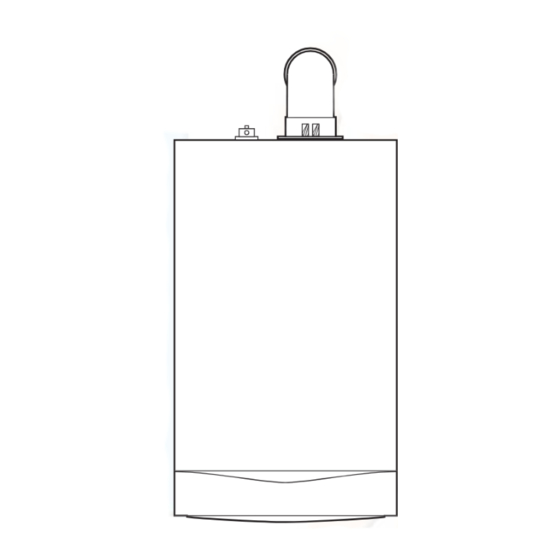
Page 11: Dimensions And Fixings
5.0 Dimensions and Fixings Dimensions A 780mm 1.5° to 3 B 345mm C 450mm D 116mm Ø Min. E 185mm (207mm for 80/125mm flue systems) F 145mm G 131mm 360° Orientation H 180mm Tube Ø 100mm Tap Rail 32.5 mm Condensate Drain 130 mm... -
Page 12: System Details
6.0 System Details Central Heating Circuit 1. The appliance is suitable for fully pumped SEALED SYSTEMS ONLY. Treatment of Water Circulating Systems • All recirculatory water systems will be subject to corrosion unless an appropriate water treatment is applied. This means that the efficiency of the system will deteriorate as corrosion sludge accumulates within the system, risking damage to pump and valves, boiler noise and circulation problems. - Page 13 6.0 System Details System Filling and Pressurising 1. A filling point connection on the central heating return pipework must be provided to facilitate initial filling and pressurising and also any subsequent water loss replacement/refilling. 2. The filling method adopted must be in accordance with all relevant water supply regulations and use approved equipment.
-
Page 14: Site Requirements
7.0 Site Requirements 450mm 5mm Min 5mm Min Location 1. The boiler may be fitted to any suitable wall with the flue 200mm Min passing through an outside wall or roof and discharging to (300mm Min if using 80/125mm atmosphere in a position permitting satisfactory removal of flueing system) combustion products and providing an adequate air supply. - Page 15 7.0 Site Requirements Ventilation of Compartments Gas Service Cock 1. Where the appliance is installed in a cupboard or compartment, no air vents are required. 2. BS 5440: Part 2 refers to room sealed appliances installed in compartments. The appliance will run sufficiently cool without ventilation.
- Page 16 7.0 Site Requirements Condensate Drain Termination to an internal soil and Boiler vent pipe FAILURE TO INSTALL THE CONDENSATE DISCHARGE PIPEWORK CORRECTLY WILL AFFECT THE RELIABLE OPERATION OF THE BOILER The condensate discharge pipe MUST NOT RISE at any point along its length.
- Page 17 Terminal Position with Minimum Distance (Fig. 9) (mm) 7.0 Site Requirements A a Directly below an opening, air brick, opening windows, etc. B a Above an opening, air brick, opening window etc. Flue C a Horizontally to an opening, air brick, opening window etc. D Below gutters, soil pipes or drain pipes.
-
Page 18: Flue Options
8.0 Flue Options Horizontal Flue Systems 1. The standard flue is suitable only for horizontal termination applications. 2. Maximum permissible equivalent flue lengths are:- 60/100 80/125 Horizontal Concentric 10 metres 20 metres 3. Any additional “in line” bends in the flue system must be taken into consideration. - Page 19 Vertical Flues 8.0 Flue Options (Twin Pipe) Twin & Vertical Flue Systems 1. Maximum permissible equivalent flue lengths are:- (60/100) (80/125) Vertical Concentric 10 metres 20 metres Vertical Twin Pipe 15 metres 2. Any additional “in line” bends in the flue system must be taken into consideration.
- Page 20 8.0 Flue Options Flue Accessories Accessory Size Code No FLUE GROUP A Concentric Flue System 100mm diameter Horizontal Flue Terminal (incl elbow) 5118489 Telescopic Flue (inc. elbow) 315-500mm 5119654 Telescopic Internal Flue Kit 315-500mm 5119654 Flue Extension 1000mm 5111074 Flue Bend 93°...
- Page 21 8.0 Flue Options For Twin Flue Systems fit the adaptors as follows:- Flue Duct Adaptor 1. Engage the flue duct adaptor on the boiler flue adaptor, making sure that it is pushed down as far as possible. Air duct adaptor 1.
- Page 22 8.0 Flue Options For Roof Terminals 1. In the case of a pitched roof 25 - 50 degrees, position the lead Approx tile to replace/flash over existing roof tiling. Make an aperture in 1425mm the roof suitable for the lower tube of the roof terminal and ensure the integrity of the roof cover is maintained.
-
Page 23: Plume Displacement
93° Elbow/Plume 9.0 Plume Displacement Outlet Assembly 60Ø Support Plume Displacement Kit (Fig. 14) O Ring Bracket Kit No 5118638 (5121367 without elbow) Content of kit 0.9 metres 0.9m 60/100 Concentric Flue 1m 60 Dia Exhaust Flue Pipe 60Ø Exhaust Adaptor Flue Pipe 60 Dia Support Brackets... - Page 24 45° Elbow 93° Elbow Flue Length - Worked Example 1 metre Extension Potterton Promax System 32 HE Concentric 60/100 Flue In Fig. 18 opposite an additional 93° bend and pair of 45° 1 metre supplied in kit bends have been included in the 60Ø exhaust.
- Page 25 9.0 Plume Displacement General Fitting Notes 1. Cut a hole in the external wall which the concentric flue assembly will pass through. The hole should allow the flue to fall back to the boiler at an angle of 3°. 2. When completed the terminal must be at least 2 metres above ground level (Fig.
- Page 26 9.0 Plume Displacement Plume Outlet Elbow General Fitting Notes (cont.) 15. For aesthetic purposes it is permissible to route the 60Ø exhaust in an enclosed box, but the air inlet and plume outlet MUST remain in free air. 16. It is also possible to separate the plume outlet from the 93°...
-
Page 27: Installation
10.0 Installation 10.1 Unpacking & Initial Preparation The gas supply, gas type and pressure must be checked for suitability before connection (see Section 7.4). 1. If pre-plumbing is required turn the unopened carton over and remove the staples. Open the flaps and remove the cardboard sheet, template and wall plate. - Page 28 10.0 Installation Wall Plate 10.3 Fitting The Boiler 1. Lift the boiler using the Lifting Points as shown by the shaded areas (Fig. 36). The boiler should be lifted by TWO PEOPLE. Engage the slots at the top rear of the boiler on the wall plate (Fig.
- Page 29 10.0 Installation 10.6 Fitting The Flue HORIZONTAL FLUE 1. The standard flue is suitable for lengths between 100mm minimum and 685mm maximum, as measured from the Fig. 39 edge of the flue elbow outlet to the joint between the terminal and air duct (Fig. 39). 2.
- Page 30 10.0 Installation Inner Flue Support Bracket 10.6 Fitting the Flue (Cont) 6. The inner flue duct support bracket may be in the waste portion of the flue. In this case retrieve the bracket before discarding the waste. 7. Take the inner flue support bracket (if not already fitted) Fig.
- Page 31 10.0 Installation 10.7 Making The Electrical Connections The boiler is fitted with a 1.3m length of 3 core of cable. This can be connected to the fused 3A 230V 50H supply. NOTE: Both the Live and Neutral connections are fused. To connect an external control proceed as follows:- 1.
-
Page 32: Commissioning
Heat Exchanger 11.0 Commissioning Automatic Air Vent Fig. 51 11.1 Commissioning the Boiler 1. Reference should be made to BS 5449 Section 5 when commissioning the boiler. IMPORTANT: The heat exchanger air vent on top of the boiler (Fig. 51) MUST be opened before filling the primary Screw system. - Page 33 11.0 Commissioning 11.2 Checking 1. The gas valve is factory set and the burner pressure cannot be measured as it is altered by suction of the fan and modulates as demand on the boiler alters. The gas supply pressure should be 20mb. 2.
-
Page 34: Completion
12.0 Completion 12.1 Completion Case Front Panel 1. Instruct the user in the operation of the boiler and system including the integral timer, explaining the operational sequence. 2. Set the central heating and hot water temperature control knobs to the requirements of the user. 3. -
Page 35: Servicing
13.0 Servicing 13 .1 Annual Servicing Case Front Panel 1. For reasons of safety and economy, it is recommended that the boiler is serviced annually. Servicing must be performed by a competent person. If a combustion analyser is available the CO can be checked and adjusted - see Section 15.0. - Page 36 13.0 Servicing 13.1 Annual Servicing (Cont) Burner Viewing Window 7. Undo the nut on the gas inlet pipe to the venturi (Fig. 65) and pull the sensing pipe off the fan. 7.5 ± 1 8. Disconnect the electrode leads, noting their position, and the fan electrical plugs (Fig.
-
Page 37: Changing Components
14.0 Changing Components IMPORTANT: When changing components ensure that both the gas and electrical supplies to the boiler are Bracket isolated before any work is started. When the component has been changed turn the selector switch fully anticlockwise against the spring pressure to the Igniter reset position and hold for 5 seconds to reset the boiler before recommissioning. - Page 38 14.0 Changing Components 14.3 Fan (Fig. 69) 1. Undo the nut on the gas inlet pipe to the venturi (Fig. 70) and pull the sensing pipe off the fan. 2. Disconnect the electrode leads, noting their position and disconnect the fan electrical plugs. 3.
- Page 39 14.0 Changing Components Cover 14.6 Burner (Fig. 72) Burner 1. Undo the screws securing the collector to the venturi and extension piece. Remove this extension piece from the Gasket cover (on 24 models). Extension Piece (Not on 28 model) 2. Withdraw the burner from the cover and replace with the new one.
- Page 40 14.0 Changing Components 14.8 Flue/Heat Exchanger Thermostat Sensor Electrical (Fig. 74) Plug Flue/Heat Exchanger Thermostat Sensor 1. Ease the retaining tab on the sensor away and disconnect the electrical plug. 2. Turn the sensor 90 anticlockwise to remove - it is a bayonet connection.
- Page 41 14.0 Changing Components 14.13 Pump - Head Only (Fig. 78) 1. Drain the primary circuit and remove the socket head screws securing the pump head to the body and draw the head away. 2. Undo the screw on the pump wiring cover and remove the cover.
- Page 42 14.0 Changing Components 14.16 Pressure Gauge (Figs. 81 & 82) Gauge Retaining Bracket 1. Drain the primary circuit and undo the nut on the pressure gauge capillary. 2. Undo the screws securing the gauge retaining bracket. 3. Remove the bracket and gauge assembly. Depress the barbs on the side of the gauge and remove the retaining bracket.
- Page 43 14.0 Changing Components 14.18 P.C.B. (Fig. 85) 1. Note the settings of the temperature control knobs, rotate them fully anticlockwise and carefully pull them off the drive pins. 2. Completely undo the screws securing the control box cover and release the cover retaining barbs from their slots. Disengage the rear of the cover from the control box hinge pin (Fig.
- Page 44 14.0 Changing Components 14.20 Gas Valve (Fig. 86) IMPORTANT: After replacing the valve the CO must be Venturi Inlet checked and adjusted as detailed in Section 15.0 Pipe Combustion Check. Only change the valve if a suitable calibrated combustion analyser is available Outlet Adaptor 1.
-
Page 45: Combustion Check
15.0 Combustion Check 15.1 Checking the CO IMPORTANT: The CO must be only be checked and adjusted if a suitable calibrated combustion analyser is available. 1. The combustion (CO ) may be checked after running the boiler for several minutes. To do this it is necessary to set the boiler to ‘Calibration Mode’. -
Page 46: Electrical
16.0 Electrical 16.1 Illustrated Wiring Diagram Central Heating NTC Sensor Overheat Stat Return Heating Water Pressure Temperature Sensor Flue Sensor Switch X400 X401 9 8 7 6 5 4 3 2 1 8 7 6 5 4 3 2 1 Control PCB X501 Pump... -
Page 47: Short Parts List
17.0 Short Parts List Short Parts List G.C. Description Manufacturers Part No. Flue Thermostat 5114747 Burner (12/15/18) 5122149 Burner (24) 5114697 Burner (32) 5114698 5114684 Igniter Electrode 5114702 Sensing Electrode 5114703 Pump 248042 Water Pressure Switch 5114748 Overheat Thermostat 5114729 NTC Sensor 5114725 Gas Valve... -
Page 48: Fault Finding
18.0 Fault Finding 18.1 Initial Fault Finding Checks NOTE: When instructed to turn the 1. Check that gas, water and electrical supplies are available selector to the reset position turn the at the boiler. selector switch fully anticlockwise against the spring pressure to the reset position 2. -
Page 49: Baxi Heating Uk Ltd
18.0 Fault Finding Refer to Section 16.0 “Illustrated Wiring Diagram” for position of terminals and components Central Heating - Follow operational sequence Turn selector switch to Go to section ‘A’ The display illuminates Error 110 flashing If the error 110 is still flashing. Turn the selector switch to Error 130 flashing reset position for 5 seconds... - Page 50 18.0 Fault Finding Fault Finding Solutions Sections Is there 230V at: Main terminals L and N Check electrical supply Main terminal fuse Replace fuse Display Replace PCB illuminated Check wiring PCB - X1 connector terminals 1,2 Is there 230V at: Pump If pump jammed, release Replace pump...
- Page 51 18.0 Fault Finding Temperature sensors faulty. Cold resistance approximately 10kΩ @ 25° C (DHW and CH sensors) Replace sensor 20kΩ @ 25° C (Flue sensor) (resistance reduces with increase in temp.) Check and correct the connection of the tube between the venturi and gas valve Gas at burner Ensure gas is on and purged PCB - X3 connector is 230V AC across...
- Page 52 18.0 Fault Finding Check the gas supply pressure: For Natural Gas greater than 10 - 11 mbar Check and correct if necessary 1. The mechanical set of the gas valve (CO2 values - see instruction) 2. Flame sensing electrode and lead connections 3.
- Page 53 19.0 Notes © Baxi Heating UK Ltd 2007 Supplied By www.heating spares.co Tel. 0161 620 6677...
- Page 54 5 1 1 4 4 4 2 BENCHMARK No. 1.0 Introduction GAS BOILER COMMISSIONING CHECKLIST C O L L E C T I V E M A R K BOILER SERIAL No. NOTIFICATION No. CONTROLS To comply with the Building Regulations, each section must have a tick in one or other of the boxes TIME &...
-
Page 55: Service Interval Record
SERVICE INTERVAL RECORD It is recommended that your heating system is serviced regularly and that you complete the appropriate Service Interval Record Below. Service Provider. Before completing the appropriate Service Interval Record below, please ensure you have carried out the service as described in the boiler manufacturer’s instructions. -
Page 56: Description
A Tr ad in g D i v i s io n of B axi He at i ng UK Lt d Brooks House, Coventry Road, Warwick. CV34 4LL After Sales Service 08706 017 017 Technical Enquiries 08706 049 049 Website www.potterton.co.uk e&oe 925.071.1... - Page 57 Promax System User’s Guide and HE Plus Important Warranty Information Range Please keep these instructions in a safe place. If you move house, please hand them over to the next occupier. © Baxi Heating UK Ltd 2007 Supplied By www.heating spares.co Tel. 0161 620 6677...
- Page 58 Contents Section Page Natural Gas Quick Reference Guide Potterton Promax System 12 HE Plus G.C.N 41 591 90 Troubleshooting Potterton Promax System 15 HE Plus G.C.N 41 591 91 Potterton Promax System 18 HE Plus Repressurising System G.C.N 41 591 92...
-
Page 59: Quick Reference Guide
1.0 Quick Reference Guide Reset ON/OFF/Reset Display Central Heating Calibration Control System Pressure Gauge Selector Switch Temperature Control Reset Reset Reset OFF Position Central Heating & Hot Water Reset The boiler will not operate. Both Heating & Hot Water will operate. Hold for approx 5 seconds and release. -
Page 60: Troubleshooting
Boiler not working 2.0 Troubleshooting START Make sure the gas supply is Is the ( ) light on and the Is the ON/OFF/Reset turned ON and check if other ) on ? Select Switch in the gas appliances are operating ) position and (e.g. - Page 61 2.0 Troubleshooting Is the Timer ON and calling for Is the Room Thermostat (if heat ? fitted) set high enough ? Typical examples of external timer CH ON CH OFF Turn Room Thermostat to maximum setting (typical example shown). Ensure timer is set for Central Heating ON (see any instructions supplied with timer).
-
Page 62: Repressurising System
3.0 Repressurising System Central Heating System Pressure 1. The normal operating water pressure is between 1 and 2.5 bar (Fig. 1). If the pressure exceeds 3 bar the safety pressure valve will operate and a fault is indicated. Contact your installer. Fig. -
Page 63: Clearances
4.0 Clearances For your Safety 450mm 5mm Min 5mm Min 1. This appliance must have been installed in accordance with the manufacturer’s instructions and the regulations in force. 200mm Min (300mm Min if 2. Any modification that may interfere with the normal using 80/125mm operation of the appliance without express written flueing system... -
Page 64: Care Of The Boiler
5.0 Care of the Boiler Cleaning the Outer case The painted panels should be wiped with a damp cloth and then dried completely. DO NOT USE ABRASIVE CLEANING AGENTS. Protection & Precaution 1. The boiler incorporates an integral frost protection feature that will operate when the selector switch is in the ( position. -
Page 65: Legislation
6.0 Legislation Installation, Commissioning, Service & Repair 1. This appliance must be install in accordance with the manufacturer’s instructions and the regulations in force. Read the instructions fully before installing or using the appliance. 2. In GB, this must be carried out by a competent person as stated in the Gas Safety (Installation &... -
Page 66: Notes
7.0 Notes © Baxi Heating UK Ltd 2007 Supplied By www.heating spares.co Tel. 0161 620 6677... -
Page 67: Emergency
8.0 Emergency Warning ! If you smell gas Turn off the gas supply at the meter and call your gas supplier immediately. It is possible to isolate the boiler and at the isolating valve (Fig. 8). In GB, Transco operate a 24 hour emergency service and the telephone number will be listed in your telephone directory. -
Page 68: Warranty & Service
To arrange an annual service After Sales Service 08706 017 017 Technical Enquiries 08706 049 049 from one of our Baxi Heating UK Ltd heating experts, please call to arrange a Website www.potterton.co.uk visit convenient to you. e&oe ompany 925.072.1...
Need help?
Do you have a question about the HE Plus and is the answer not in the manual?
Questions and answers