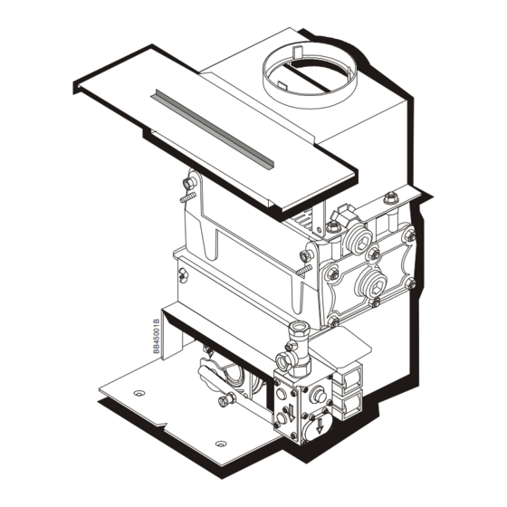
Potterton Housewarmer 45 Installation & Service Instructions Manual

Potterton Housewarmer 45 Installation & Service Instructions Manual

Advertisement

Installation & Service Instructions
THE GAS SAFETY (INSTALLATION AND USE) REGULATIONS 1994 (as amended).
'' In your own interest, and that of safety, it is law that all gas appliances are installed by competent persons,
in accordance with the above regulations. Failure to install appliances correctly could lead to prosecution.''
Installation must be in accordance with these installation & Service Instructions and the rules in force.
The polythene bags used for packaging are a potential hazard to babies and young children
LEAVE THESE INSTRUCTIONS WITH THE USER FOR USE ON FUTURE CALLS
For Use With Natural Gas
(G20) Only At 20mbar
For Use in GB & IE
Housewarmer 45 & 55
Gas Fired Electronic Back Boilers
and MUST BE DISPOSED OF IMMEDIATELY.
Potterton Housewarmer 45 - G.C. No. 44 590 18
Potterton Housewarmer 55 - G.C. No. 44 590 19
IMPORTANT
PLEASE READ THIS BOOK
BEFORE INSTALLING,
OPERATING OR SERVICING
THIS APPLIANCE.

Advertisement

Table of Contents
loading
Need help?

Need help?

Do you have a question about the Housewarmer 45 and is the answer not in the manual?

Questions and answers

Subscribe to Our Youtube Channel

Summary of Contents for Potterton Housewarmer 45

  • Page 1 Potterton Housewarmer 45 - G.C. No. 44 590 18 Potterton Housewarmer 55 - G.C. No. 44 590 19 Installation & Service Instructions Housewarmer 45 & 55 Gas Fired Electronic Back Boilers THE GAS SAFETY (INSTALLATION AND USE) REGULATIONS 1994 (as amended).
  • Page 2: Table Of Contents

    Instruct the User ........19 Gas Fires The Potterton Housewarmer 45 & 55 Back Boiler Units can be fitted with a variety of approved Potterton Housewarmer Gas Fires. The range comprises of Radiant, Live Fuel Effect and Inset Decorative Models. Accessories...
  • Page 3: Technical Data

    1. Technical Data – Page 3 Potterton Potterton Housewarmer 45 Housewarmer 55 Heat Input 16.8kW (57,300Btu/h) 20.4kW (69,620Btu/h) Heat Output 13.2kW (45,000Btu/h) 16.1kW (55,000Btu/h) Gas Rate 1.6m³/h (56.5ft³/h) 1.95m³/h (68.78ft³/h) Inlet Pressure 20mbar 20mbar Burner Pressure 13.4mbar (5.36in wg) 15.5mbar (6.20in wg)
  • Page 4: General

    Local Building Regulations Latest edition of I.E.E. Regulations This Potterton boiler is part of a combined back boiler and By-Laws of the Local Water Undertaking and the Current gas fire unit, which should be fitted in a fireplace or standard Edition of the following standards:- builder's opening, at the base of a chimney.
  • Page 5 Installation & Service Instructions or otherwise recommended in writing. Any direct connection of a control device not approved by Potterton Myson Ltd, could invalidate the CE Certification and normal appliance warranty.
  • Page 6: Installation Requirements

    3. Installation Requirements – Page 6 The System If a three port diverter valve is used as shown in Figs.5 & 6, a by-pass is not necessary since one circuit is always open. Where a pair of two port valves are used, a by-pass is The boiler must be used on INDIRECT hot water systems necessary.
  • Page 7 3. Installation Requirements – Page 7 To size the expansion vessel it is first necessary to calculate Cylinder the volume of water in the system in litres. The following The hot water cylinder must be an indirect coil type or a volumes may be used as a conservative guide to calculating direct cylinder fitted with an immersion calorifier suitable for the system volume.
  • Page 8 3. Installation Requirements – Page 8 An Anti Gravity Check Valve, Or Some Other Mechanical Device (E.G. Motorised Valve, By-pass Using Bathroom Gate Valve), Should Be Fitted Radiator Connection Into To The Radiator Circuit Where Gravity Circuit & Fitted It Is Required To Prevent With Two Lockshield Gravity Circulation When Valves To Be Installed...
  • Page 9 3. Installation Requirements – Page 9 Make Up F ully P umped Vessel S ealed S ystem Optional Pressure 3 Port Vent Gauge Valve Safety Alternative By-pass Valve Optional arrangement Using Zone The Bathroom Valves Radiator Fitted With Expansion Two Lockshield Valves Vessel Flow Filling...
  • Page 10: Fireplace Opening & Hearth

    3. Installation Requirements – Page 10 Fireplace Opening & Hearth For all installations the boiler requires a standard builder's The flat surface area and hearth requirements are shown in brickwork opening (fireplace recess) irrespective of the fire the Installation & Service Instructions supplied with the fire. model fitted.
  • Page 11: Chimneys & Flues

    3. Installation Requirements – Page 11 Chimneys & Flues Approved A flue system (lined throughout its Terminal length) must be provided to evacuate the flue products of combustion from the boiler. Reference should be made to the building regulations and BS 5440:1. and the flue system efficiency should be Cement Sealing...
  • Page 12: Electricity Supply

    3. Installation Requirements – Page 12 The recommendations of BS 6891 & BS 6400 must be Electricity Supply observed. Any part of the gas supply pipe running within the chimney recess, should be suitably protected, (e.g. coated or A 230-240v ~ 50 Hz, single phase electricity supply fused to wrapped with PVC tape).
  • Page 13 4. Installation – Page 13 Locate the boiler in the fireplace opening ensuring that Before Securing the 'V' in the front plate is about the centreline of the The Boiler Check opening and horizontally aligned with the front To See If It Is opening.
  • Page 14 4. Installation – Page 14 Loosely fit the gas service cock to the gas valve. Combustion Closed Open Chamber Re-fit the burner/gas valve assembly and secure with Main Burner (45 Model) the screw previously removed. Re-fit the combustion chamber front cover and secure using the wing nuts previously removed.
  • Page 15 4. Installation – Page 15 Illusion Bracket User Control Insert Screws Into User Control For Illusion, Illusion 2, Straton, Presence Presence 2, Firestar & Knightsbridge - See The Installation & Service Instructions Supplied With The Fire Fig. 16...
  • Page 16: Electrical Connections

    4. Installation – Page 16 4.3 Electrical Connections The boiler and all external control circuit wiring must be supplied from the same single isolating switch or plug and socket, and should be fused at 3A. Care must be taken to ensure that all wiring to the boiler will not contact any sharp edges or hot surfaces.
  • Page 17 4. Installation – Page 17...
  • Page 18: Commissioning

    Set the boiler be carried out by a suitably qualified personnel. switch to 'Off' and drain the system whilst still hot. Potterton Myson offer this service on a chargeable basis. Important Note: Should the boiler fail to operate correctly refer to the...
  • Page 19: Final Checks

    5. Commissioning – Page 19 Timer Switch Final Checks This switch is internally connected to the gas control valve OxyPilot Burner circuit and a timed pump over-run circuit. The pilot is pre-set and no adjustment is required. When lit At switch position '3' the main burner will remain off for the pilot flame envelope should just cover the electrode tip approximately 3 minutes following operation of the control and spark earthing post.
  • Page 20: Servicing & Replacement Of Parts

    6. Servicing & Replacement of Parts – page 20 WARNING: Before commencing work turn the fire off, turn the boiler switch to 'OFF'' and Isolate the electricity supply to the boiler. Allow the fire and boiler to cool. IMPORTANT: Always test for gas soundness after completing any replacement of gas carrying components and carry out functional checks of controls.
  • Page 21: Lint Guard

    6. Servicing & Replacement of Parts – page 21 Lint Guard Clip the cut-out under the bottom edge of the OxyPilot Assembly OxyPilot Pull the guard backwards horizontally. Assembly Clean the gauze using a brush or vacuum cleaner. Re-assemble in reverse order. Lint OxyPilot Guard...
  • Page 22: Gas Valve

    6. Servicing & Replacement of Parts – page 22 Gas Valve Gas Pressure Main Burner Adjusting (45 Model) Screw Perform section 6.2. Remove the screw securing the gas valve electrical plug to the valve. Pull off the Remove plug and remove the gasket. Remove the 4 bolts securing the burner feed pipe to the base of the gas valve.
  • Page 23 6. Servicing & Replacement of Parts – page 23 Control Gas Fire Stat Overheat Mounting Bracket Stat Legend/ Mainflame Shown Cable Clip Bracket Securing Wing (2 off) Securing Screw Electronic Securing Control Screws (2 off) User Gas Fire Controls Isolation Closed Fig.
  • Page 24: Fault Finding

    7. Fault Finding – Page 24 INVESTIGATE CAUSE OF LOCKOUT. START TURN BOILER STANDBY a. BLOCKED PILOT. SWITCH TO ON b. OVERHEAT. c. INADEQUATE ROOM VENTILATION. d. INADEQUATE FLUE DRAUGHT. IS INDICATOR SHOWING DOES LED INDICATOR MOMENTARILY PRESS RESET DOES THE LED EXTINGUISH? GREEN? BUTTON COME ON IMEDIATELY?
  • Page 25: Electrical Diagrams

    8. Electrical Diagrams – Page 25...
  • Page 26: Flow Diagrams

    9. Flow Diagrams – Page 26 Live Neutral Standby Room Stat Switch (User Ignition PL6-12 PL2-1 PL6-11 Control) Electrode Timer Main Gas Valve PL4-4 Gravity Spark Generator Link PL2-3 PL2-2 PL5-1 PL5-3 Stat PL4-5 PL4-3 PL2-4 T1-T5 Pilot Gas Valve Mains Transformer Tx1 PUMP Flame Sensing...
  • Page 27: Short List Of Spares

    10. Short List Of Spares – Page 27 Fig. 31 Item Description Potterton G.C. Part No. Part No. Gas Control Valve Kit - Incl. Item 2 930003 289 865 Double Solenoid Actuator - SIT 0.007.412 929097 397 764 OxyPilot Assembly - SIT...
  • Page 28 Part No. 966/9350/1 – 02 Potterton Housewarmer Illusion ASD - G.C. NO. 37 590 16 966 Inset DGF with ILLUSION FACIA Potterton Housewarmer Stratton ASD - G.C. NO. 37 590 17 966 Inset DGF with STRATTON FACIA Potterton Housewarmer Presence ASD - G.C. NO. 37 590 18 966 Inset DGF with PRESENCE FACIA Installation &...
  • Page 29 11.4 Lint Trap.................................. 16 11.5 Piezo Unit ................................16 11.6 Gas Tap.................................. 17 12. Short List of Spares................................ 19 If you have any problems or questions concerning this appliance, please contact the Potterton Myson Technical Help Line - Telephone (01926) 410044.
  • Page 30: Technical Data

    1. Technical Data - Page 3 Illusion Stratton Presence Weight - Packed - Fire 23.90kg (52.7lb). 23.90kg (52.7lb). 23.90kg (52.7lb). Weight - Unpacked - Fire 18.98kg (41.8lb). 18.98kg (41.8lb). 18.98kg (41.8lb). Weight - Packed - Facia 21.25kg (46.8lb). 17.00kg (37.5lb). 8.30kg (18.3lb).
  • Page 31: General

    The 966 is an inset decorative gas fire. It is lit by a piezo spark igniter so batteries or electricity are not required. When fitted with either the Illusion, Stratton or Presence Facia, this fire is only suitable for use with the Potterton Housewarmer 45 & 55 BBu's.
  • Page 32: Hearths, Walls, Fire Surrounds, Shelves & Clearances

    General - Page 5 3.2. Hearths, Walls, Fire Surrounds, Shelves & Clearances. Hearths The fire MUST be installed onto a non-combustible hearth. The hearth must be to the dimensions shown in Fig. 2. Walls If the wall against which the fire is to be mounted has a combustible cladding or surround, the following conditions must be met:- 1.
  • Page 33: Installation

    4. Installation - Page 6 4.1. Unpack the Fire The fire is supplied in 2 packs. Pack 2 of 2 contains:- The Convector Box. Burner Tray. Spillage Plate. Outer Metal Surround. Ceramics Pack. Control Board Mounting Bracket. Bag of Fittings. Poly Bag containing these Instructions and other literature.
  • Page 34 Installation - Page 7...
  • Page 35 Installation - Page 8...
  • Page 36 Installation - Page 9 4.4. Install the Convector Box a) Attach the self adhesive foam strip along the sides and top of the outer edge of the convector box at the rear. b) Hook the spillage plate over the top edge of the firebox as shown in figure 6 and secure using the 2 No.6 x 9.5mm screws from the bag of fittings.
  • Page 37: Check Gas Pressure & Operation Of The Fire

    6. Check Gas Pressure & Operation Of Fire - Page 10 The test point screw is located on the left hand side of the controls assembly near the gas tap. a) Remove the pressure test point screw and connect a pressure gauge. b) Push in and turn the control knob anti-clockwise to the ' ' (ignition/pilot) setting and the pilot should...
  • Page 38: Fitting The Facia

    8. Fitting The Facia - Page 11 a) Loosen the 2 facia fixing bracket screws (1 each side) located at the bottom of the convector box and slide the brackets towards the centre of the appliance. Temporarily re-tighten the screws. b) Lift the facia and position it centrally on the convector box ensuring that the 2 lugs at the top of the facia locate in the 2 holes at the top of the convector box.
  • Page 39: Complete The Installation

    9. Complete The Installation - Page 12 Locate the Plinth into position at the front of the appliance. In the interests of hygiene please wash your hands on completion of the installation. Leave the bag of vermiculite with the consumer to allow them to top up the burner tray.
  • Page 40: Servicing & Cleaning

    10 Servicing & Cleaning - Page 13 Refer to the separate boiler instructions supplied with the boiler for cleaning the boiler. To ensure continued efficient operation of the appliance, it is recommended that it is checked and cleaned as necessary at regular intervals.
  • Page 41: Replacement Of Parts

    11. Replacement of Parts - Page 14 11.1. General Access a) Carefully pull the plinth away from the fire. b) Remove the facia (2) by slackening off or removing the facia fixing brackets at the base of the facia. Lift the facia off the convector box.
  • Page 42 Replacement of Parts - Page 15 c) Close the gas fire isolation tap and undo the union. d) Loosen the 2 wing nuts securing the burner tray to the convector box, then carefully remove the burner tray. e) To avoid accidental spillage, carefully empty the vermiculite (Ash Effect) out of the burner tray into a suitable container and put somewhere safe.
  • Page 43: Burner Injector

    Replacement of Parts - Page 16 11.3. Burner Injector a) Perform General Access - 11.1. b) Disconnect the union nut securing the pipe to the injector carrier. c) Remove the screw securing the injector carrier to the injector box then carefully withdraw the injector carrier. d) Unscrew injector from the injector carrier.
  • Page 44: Gas Tap

    Replacement of Parts - Page 17 11.6. Gas Tap a) Perform General Access - 11.1. b) Pull the control knob off the gas tap. c) Remove the 2 screws securing the bezel around the tap. Remove the bezel. d) Pull the electrode lead off the piezo unit. e) Unscrew the thermocouple from the rear of the gas tap.
  • Page 45: Short List Of Spares

    12. Short List Of Spares - Page 18 Drg. G.C. Description Makers Ref. Part No. 389 583 Burner Injector - Bray CAT 28/340 966/705 158 582 Tap Assembly - Includes Drg. Ref. 3 364/1044 385 855 Piezo Unit 942/9387 127 293 Pilot Burner Assembly (Atmospheric Sensing Device) 960/1433 127 022...

This manual is also suitable for:

Housewarmer 55

Table of Contents

Save PDF