Table of Contents
Advertisement
Quick Links
Advertisement
Table of Contents

Related Manuals for Matrix mvBlueFOX3

Summary of Contents for Matrix mvBlueFOX3
- Page 1 ProductFeatures...
-
Page 3: Table Of Contents
5.2.3 Installing.........................18 5.2.4 Optimizing performance and life time ..............18 5.2.5 Connectors ......................18 5.2.6 Cleaning.........................18 5.2.7 Adjusting the C-mount (mvBlueFOX3-2xxx-1xxx) ..........18 5.2.8 Adjusting the C-mount (mvBlueFOX3-2xxx-2xxx) ..........19 5.3 European Union Declaration of Conformity statement ............20 5.4 Legal notice ........................26 5.4.1 For customers in the U.S.A..................26... - Page 4 Table of Contents 6 Introduction 6.3 What's inside and accessories ..................31 6.3.1 Accessories for the mvBlueFOX3................31 7 Quickstart............................33 7.1 Driver concept .........................33 7.1.1 LabVIEW support....................35 7.2 Windows.........................35 7.2.1 System requirements.....................35 7.2.2 Installing the mvGenTL-Acquire driver ..............35 7.2.3 Connecting the camera..................38 7.3 Linux..........................39...
- Page 5 16.3.1 Registering devices ....................132 16.3.2 Renaming devices ....................134 16.3.3 Make silent registration..................135 17 Troubleshooting........................137 17.1 There are Image Error Counts..................137 17.2 I cannot see the mvBlueFOX3 or I can see it but I cannot use it........137 17.3 I get an oscillating frame rate..................143...
- Page 6 18.10 Working with several camera simultaneously............245 18.10.1 Creating synchronized acquisitions using timers..........245 19 Glossary............................251 20 Appendix A.1 Pregius CMOS specific camera / sensor data ..........257 20.1 mvBlueFOX3-2024 (2.4 Mpix [1936 x 1216]) ..............257 20.1.1 Introduction......................257 20.1.2 Spectral Sensitivity .....................257 20.1.3 Timings .......................258...
- Page 7 Table of Contents 20 Appendix A.1 Pregius CMOS specific camera / sensor data 20.1.4 Device Feature And Property List..............261 20.2 mvBlueFOX3-2024a (2.4 Mpix [1936 x 1216]) ............357 20.2.1 Introduction......................357 20.2.2 Spectral Sensitivity .....................357 20.2.3 Timings .......................358 20.2.4 Device Feature And Property List..............361 20.3 mvBlueFOX3-2032 (3.2 Mpix [2064 x 1544]) .
- Page 8 Table of Contents 21 Appendix A.2 CMOS specific camera / sensor data 21.2 mvBlueFOX3-1012d (1.2 Mpix [1280 x 960]) ............1342 21.2.1 Introduction......................1342 21.2.2 Spectral Sensitivity ...................1343 21.2.3 Timings ......................1344 21.2.4 Device Feature And Property List..............1345 21.3 mvBlueFOX3-1013 (1.3 Mpix [1280 x 1024]) ............1438 21.3.1 Introduction......................1438...
-
Page 9: Imprint
MATRIX VISION website. MATRIX VISION cannot guarantee that the data is free of errors or is accurate and complete and, therefore, assumes no liability for loss or damage of any kind incurred directly or indirectly through the use of the information of this document. -
Page 10: Introduction
(http://www.libusb.org/), which comes under LGPL 2.1. The full license text is included in the Linux distribution of the mvBlueFOX driver package. The source code for the modified version of libusb can be obtained by contacting MATRIX VISION GmbH or it can be downloaded from here: http://gpl.matrix-vision.com (navigate to others/libusb). -
Page 11: Libusbk License
1 Imprint 1.6.1 libusbK license APPLICABLE FOR ALL LIBUSBK BINARIES AND SOURCE CODE UNLESS OTHERWISE SPECIFIED. PLEASE SEE INDIVI Note: Portions of dpscat use source code from libwdi which is licensed for LGPL use only. (See dpscat.c) libusbK-inf-wizard.exe is linked to libwdi which is licensed for LGPL use only. Redistribution and use in source and binary forms, with or without modification, are permitted provided that the following conditions are met: Redistributions of source code must retain the above copyright notice, this list of conditions... -
Page 12: Sha1 Algorithm
1 Imprint 1.8 SHA1 algorithm Parts of this framework make use of an open source implementation of the SHA1 algorithm written by Dominik Reichl (http://www.dominik-reichl.de). 1.9 Expat Expat is used to parse XML strings within the SDK. 1.9.1 Expat Copyright Copyright (c) 1998, 1999, 2000 Thai Open Source Software Center Ltd Permission is hereby granted, free of charge, to any person obtaining a copy of this software and associated documentation files (the "Software"), to deal in the Software without restriction, including... -
Page 13: Cppunit
1 Imprint All advertising materials mentioning features or use of this software must display the following acknowledgment: "This product includes software developed by the OpenSSL Project for use in the OpenSSL Toolkit. (http://www.openssl.org/)" The names "OpenSSL Toolkit" and "OpenSSL Project" must not be used to endorse or promote products derived from this software without prior written permission. - Page 14 1 Imprint This notice may not be removed or altered from any source distribution.
-
Page 15: Legal Notice
2 Legal notice 2.1 Introduction The firmware running on mvBlueCOUGAR-X, mvBlueCOUGAR-XD and mvBlueFOX3 devices make use of a couple of third party software packages that come with various licenses. This section is meant to list all these packages and to give credit to those whose code helped in the creation of this software. - Page 16 2 Legal notice any, must include the following acknowledgment: "This product includes software developed for the Unity Project, by Mike Karlesky, Mark VanderVoord, and Greg Williams and other contributors", in the same place and form as other third-party acknowledgments. Alternately, this acknowledgment may appear in the software itself, in the same form and location as other such third-party acknowledgments.
-
Page 17: Revisions
UseCases_section_HDR_1031C . Added sensor IMX267: mvBlueFOX3-2124a (12.4 Mpix [4112 04. August x 3008]) V1.26 Firmware: 2016 Added sensor IMX304: mvBlueFOX3-2089a (8.9 Mpix [4112 x 2176]) 1. August V1.25 Added Triggered frame burst mode 2016 24. June Updated use case V1.24... - Page 18 3 Revisions Added sensor IMX252: November V1.15 mvBlueFOX3-2032 (3.2 Mpix [2064 x 2015 1544]) 27. October Added Starting wxPropView via V1.14 2015 command line. Added sensor IMX250: 22. October V1.13 mvBlueFOX3-2051 (5.1 Mpix [2464 x 2015 2056]) Added power led states of...
- Page 19 V0.58b LAN Firmware: 1.6.393.0 2015 (2.4 Mpix [1936 x 1216]). Updated pixel clock of 21. May V0.57b LAN mvBlueFOX3-2024 (2.4 Mpix [1936 x 2015 1216]). 12. May V0.56b LAN Updated Order code nomenclature. 2015 Adapted the sensor resolution of 17.
- Page 20 V0.44b LAN Added additional I/O board for 2015 mvBlueFOX3-M to Accessories for the mvBlueFOX3 Corrected pixel clock value of sensor December V0.43b LAN mvBlueFOX3-1012b (1.2 Mpix [1280 x 2014 960]) (66 MHz). Added use case December V0.42b LAN UseCases_section_HDR_x04e. 2014...
- Page 21 12 Feb. V0.20b LAN Updated trigger modes of the sensors. 2014 Added description of sensor 07 Feb. V0.19b LAN mvBlueFOX3-1031 (3.2 Mpix [2048 x 2014 1536]). 31 Jan. Changed position of chapter "First V0.18b LAN 2014 Start" and renamed it to Quickstart.
- Page 22 Characteristics of the digital inputs. 19 Sep. V0.8b Added Image data flow. 2013 Added troubleshooting chapter: cannot see the mvBlueFOX3 or I can 06 Aug. V0.7b see it but I cannot use 2013 Added information about Status / Power LED.
-
Page 23: Graphic Symbols
In the context of the applicable statutory regulations, we shall accept no liability for direct damage, indirect damage or third-party damage resulting from the acquisition or operation of a MATRIX VISION product. Our liability for intent and gross negligence is unaffected. In any case, the extend of our liability shall be limited to the purchase price. - Page 24 4 Graphic Symbols...
-
Page 25: Important Information
We cannot and do not take any responsibility for the damage caused to you or to any other • equipment connected to the mvBlueFOX3 . Similarly, warranty will be void, if a damage is caused by not following the manual. -
Page 26: Handling And Cleaning
Do not use benzene, thinner, alcohol, liquid cleaner or spray-type cleaner. • 5.2.7 Adjusting the C-mount (mvBlueFOX3-2xxx-1xxx) The mvBlueFOX3-2xxx-1xxx does not support back focus adjustment. However, with the four screw locks at the front of the lens holder, it is possible to rotate the C-mount ring. Warning: In combination with mvBlueFOX3-2089 and mvBlueFOX3-2124 the C-mount lens holder has to look upwards during the adjusting. -
Page 27: Adjusting The C-Mount (Mvbluefox3-2Xxx-2Xxx)
5.2.8 Adjusting the C-mount (mvBlueFOX3-2xxx-2xxx) The mvBlueFOX3-2xxx-2xxx cameras allow a precise adjustment of the back focus of the C-mount by means of a back focus ring which is threaded into the C-mount and is secured by a lock nut ring which itself is secured by two screws. -
Page 28: European Union Declaration Of Conformity Statement
5 Important information Figure 2: mvBlueFOX3-2xxx-2xxx Lensholder with C-mount ring (1) and lock nut ring (2) How to proceed: Loosen screws (location as shown above by arrows) of the lock nut ring with an Allen key • (0.9 x 50). - Page 29 5 Important information MATRIX VISION corresponds to the EU guideline WEEE 2002/96/EG on waste electrical and electronic equipment and is registered under WEEE-Reg.-No. DE 25244305. RoHS All units delivered are RoHS compliant.
- Page 30 5 Important information...
- Page 31 5 Important information...
- Page 32 5 Important information...
- Page 33 5 Important information...
-
Page 34: Legal Notice
5 Important information 5.4 Legal notice 5.4.1 For customers in the U.S.A. Class B This equipment has been tested and found to comply with the limits for a Class B digital device, pursuant to Part 15 of the FCC Rules. These limits are designed to provide reasonable protection against harmful interference when the equipment is operated in a residential environment. -
Page 35: Introduction
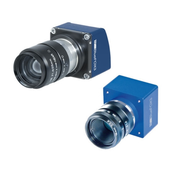
6 Introduction Figure 1: mvBlueFOX3-1 The mvBlueFOX3 is a compact USB 3.0 camera which is compliant to the brand new vision standard USB3 Vision. The mvBlueFOX3 offers a wide range of CMOS sensors, • high frame rates, • I/Os suitable for industrial applications, and •... -
Page 36: Order Code Nomenclature
6 Introduction The following figure shows the software concept of MATRIX VISION's camera devices: Figure 2: Software concept of mvBlueFOX3 As shown in figure 2, for the mvBlueFOX3 the mvIMPACT_Acquire interface is stacked on the USB3 Vision Genicam layers. The... - Page 37 6 Introduction mvBlueFOX3 - (M) A B C - (1)(2)(3)(4) - (M): Model, add "M" for single-board model - A: Sensor model 1012b: 1.2 Mpix, 1280 x 960, 1/3", CMOS 1012d: 1.2 Mpix, 1280 x 960, 1/3", CMOS 1013: 1.3 Mpix, 1280 x 1024, 1/1.8", CMOS 1020: 2.0 Mpix, 1600 x 1200, 1/1.8", CMOS...
-
Page 38: Ordering Code Samples
1: standard - (3): Case 1: standard - (4): I/O 1: standard; if I/O is needed, use separate article: mvBlueFOX3-IO The mvBlueFOX3-M2 nomenclature scheme is as follows: mvBlueFOX3-M2(A)(B) - (1)(2)(3)(4) - (A): Sensor model 024: 2.4 Mpix, 1936 x 1214, 1/1.2", CMOS 024a: 2.4 Mpix, 1936 x 1214, 1/1.2", CMOS... -
Page 39: What's Inside And Accessories
6.3 What's inside and accessories The mvBlueFOX3 is shipped without any accessories: Figure 3: mvBlueFOX3 - scope of supply For this reason, you will need at least a lens (by default, the mvBlueFOX3 is shipped without lens) and • a USB 3.0 cable •... - Page 40 MV-ZWISCHENRING Spacer for C-Mount lenses 5MM CMOUNT MV-Tripod Adapter BF3 1/4" tripod adapter including three suitable screws TRIPOD ADAPT BF3-2 Tripod adapter for mvBlueFOX3-2 mvBlueFOX3-IO I/O board for mvBlueFOX3-M (mvBlueFOX3-IO) mvBlueFOX3-IO NC I/O board for mvBlueFOX3-M (mvBlueFOX3-IO) without Hirose connector...
-
Page 41: Quickstart
7 Quickstart 7.1 Driver concept The driver supplied with the MATRIX VISION product represents the port between the programmer and the hardware. The driver concept of MATRIX VISION provides a standardized programming interface to all image processing products (excluding mvBlueLYNX) made by MATRIX VISION GmbH. - Page 42 7 Quickstart Figure 1: Driver concept 1 Part of any mvIMPACT Acquire driver installation package (Windows). • 2 Separately available for 32 bit and 64 bit. Requires at least one installed driver package. • 3 See 2, but requires an installed version of the mvBlueFOX driver. •...
-
Page 43: Labview Support
All necessary drivers for Windows are contained in the standard mvIMPACT CD-ROM or DVD-ROM. For newer driver versions we recommend to visit the MATRIX VISION website at www.matrix-vision.de, section "Products -> Cameras -> your interface -> your product -> Downloads". - Page 44 7 Quickstart mvGenTL_Acquire-x86_64-n.n.n.msi (for 64-bit systems), the installer will start • automatically: Figure 2: Driver installation - start window Now, follow the instructions of installation program • Figure 3: Driver installation - select installation folder...
- Page 45 • Figure 4: Driver installation - select features The installation will start and copies the data. At the end, MATRIX VISION's USB3 Vision • capture filter driver will be installed. A "Windows Security" dialog will appear.
-
Page 46: Connecting The Camera
/etc/FIRMWARE when working locally. 7.2.3 Connecting the camera After the driver installtion you have to connect the mvBlueFOX3 using a USB 3.0 cable. You can check connection by using tool mvDeviceConfigure. In the program's window, your camera should be listed:... -
Page 47: Linux
3.5.0 . Please refer to the documentation of your Linux distribution for information on how to update your system's Linux kernel. Following Kernels have been tested and verified by MATRIX VISION for seamless USB3 operation: Kernel 3.8.0 •... -
Page 48: Installing The Mvgentl-Acquire Driver
µPD720202 or µPD720200A. 7.3.2 Installing the mvGenTL-Acquire driver To use the mvBlueFOX3 camera within Linux (grab images from it and change its settings), a driver is needed, consisting of several libraries and several configuration files. These files are required during run time. -
Page 49: Connecting The Camera
"/etc/udev/rules.d" directory exists, which may contain several different files, each defining the behavior of a system device. In the specific case of the mvBlueFOX3 camera, if the camera has been installed through the respective installation script install_mvGenTL_Acquire.sh , a suitable set of rules has been installed automatically. -
Page 50: Optimizing Usb Performance
SUBSYSTEM!="usb|usb_device|plugdev", GOTO="mvbf_rules_end" ACTION!="add", GOTO="mvbf_rules_end" ATTRS{idVendor}=="164c", ATTRS{idProduct}=="5531", MODE="0664", GROUP="plugdev" LABEL="mvbf_rules_end" This step is only necessary if a mvBlueFOX3 in the "mvbootloader" state should be recognised by the system. Save the file(s) and exit your editor Note: The above 52-U3V.rules file provides the necessary access priviledges not only for mvBlueFOX cameras, but also for U3V-compliant cameras of any other vendor. - Page 51 7 Quickstart Passing parameters to the kernel at boot time is usually done by typing: systemModuleName.parameter=value . In our case this would be: usbcore.usbfs_memory_mb=256 How this can be done depends on the system bootloader. For systems using the GRUB2 bootloader the "/etc/default/grub"...
- Page 52 Set "usbcore.usbfs_memory_mb=256" (this will increase the buffer of the USB bus) Install the mvGenTL_Acquire driver. Now, the camera should work. If you could not find the mvBlueFOX3 driver, you would add the current user to the plugdev group: sudo usermod -a -G plugdev ubuntu...
-
Page 53: Relationship Between Driver, Firmware, Fpga File And User Settings
7.4 Relationship between driver, firmware, FPGA file and user settings To operate a GenICam based device like mvBlueFOX3 apart from the physical hardware itself 2 pieces of software are needed: A firmware running on the device. This firmware consists of •... - Page 54 7 Quickstart So assume a device with a certain firmware version is connected to a host system. During an explicit firmware update, the firmware file will be downloaded onto the device. In order to become active the device must be power-cycled: Figure 8: Firmware file will be downloaded during an firmware update...
- Page 55 7 Quickstart Figure 10: wxPropView - FPGA and Firmware version numbers Apart from the device driver and firmware relationship there are certain places where a device configuration can be stored when dealing with GenICam compliant devices: There may be User Sets which are stored in the device's non-volatile memory. User Sets •...
-
Page 56: Settings Behaviour During Startup
7 Quickstart 7.5 Settings behaviour during startup Settings contain all the parameters that are needed to prepare and program the device for the image capture. Every image can be captured with completely different set of parameters. In almost every case, these parameters are accessible via a property offered by the device driver. A setting e.g. - Page 57 7 Quickstart Whenever storing a product specific setting, the device specific setting of the device used for • storing will be deleted (if existing). So when the user is currently working with a device 'VD000001' belonging to the product group 'VirtualDevice' and there is a setting exclusively for this device storing a product specific setting now will automatically delete the setting for 'VD000001'.
- Page 58 7 Quickstart...
-
Page 59: Technical Data
Size of body (w x h x 39 x 39 x 24 mm Lens protrusion C-Mount CS-Mount 12.5 mm 7.5 mm 8.1.1.1 Mounting holes On the bottomside, the mvBlueFOX3 provides integrated tripod mounting holes. Figure 2: mvBlueFOX3 mounting holes... -
Page 60: Standard Model -2Xxx
8 Technical data Figure 3: Dimensional drawing of tripod adapter 8.1.2 Standard model -2xxx 8.1.2.1 Option -1xxx (lensholder without back focus adjustment) Figure 4: mvBlueFOX3-2xxx-1xxx dimensions and connectors mvBlueFOX3-2xxx-1xxx Size of body (w x h x 39.8 x 39.8 x 50.9 mm Lens protrusion 10.7... - Page 61 8 Technical data The mvBlueFOX3-2xxx-1xxx provides integrated mounting holes. Figure 5: mvBlueFOX3-2xxx-1xxx mounting holes 8.1.2.2 Option -2xxx (lensholder with back focus adjustment) Figure 6: mvBlueFOX3-2xxx-2xxx dimensions and connectors mvBlueFOX3-2xxx-2xxx Size of body (w x h x 39.8 x 39.8 x 37.7 mm...
-
Page 62: Model Without Housing (-M1)
In combination with the connectors, the mechanical stress needs to be limited. Figure 8: mvBlueFOX3-M dimensions and connectors 8.1.3.1 I/O board for mvBlueFOX3-M (mvBlueFOX3-IO) Figure 9: mvBlueFOX3-M dimensions of additional I/O board The following figure shows, how the additional I/O board gets connected correctly. Warning: Since the connector of the I/O board will also fit upside down, you have to be careful while connecting. -
Page 63: Model Without Housing (-M2)
Digital I/O). Note: It is also available to purchase the I/O board without Hirose connector as "mvBlueFOX3-IO NC" (NC = not connected). The pinning is provided in the figure: Figure 11: mvBlueFOX3-M dimensions of additional I/O board without Hirose connector. -
Page 64: Camera Interfaces
8 Technical data Figure 12: mvBlueFOX3-M2xxx-1xx2 dimensions and connectors 8.2 Camera interfaces 8.2.1 Circular connector male (Power / Digital I/O) Figure 13: Hirose 12-pin (male; top view), digital I/O, power mvBlueFOX3-1xxx | mvBlueFOX3-2xxx | Line in Cable KS-BCX-HR12 Pin. Signal... - Page 65 Main connector shield main shield Color assignment following international code for UL wiring. 8.2.1.2 Power Supply The mvBlueFOX3 is bus powered. Anyway, it is possible to power the mvBlueFOX3-2 externally with following specs: Input voltage range: • 12 .. 24V DC (typical) ♦...
-
Page 66: Characteristics Of The Digital Inputs
+3 to +24V (max. 30V) Low level 0V (min. -30V) to +0.7V Threshold (Low --> High / 2V +- 1V High --> Low) Figure 15: DigIn mvBlueFOX3 8.2.2.2 Switching characteristics Characteristics Symbol Test conditions Typ. Unit Minimum trigger pulse width Turn-On time... -
Page 67: Characteristics Of The Digital Outputs
Comment Min. Typ. Max. Unit load current = 7 mA CE(sat) Output Voltage Figure 16: DigOut mvBlueFOX3 8.2.3.2 Switching characteristics Characteristics Symbol Test conditions Typ. Unit Turn-On time = 100 Ohm, V 10V, I = 2mA Storage time Turn-Off time Turn-On time = 1.9 kOhm, V... -
Page 68: Standard Model -2Xxx
Bootloader was recognized and FPGA is booting-up or device is in standby 2. Red mode. 3. Green mvBlueFOX3 is running. 4. Green blink mvBlueFOX3 is busy (e.g. file upload). 8.3.2 Standard model -2xxx States Description 1. Off No power or no bootloader found. -
Page 69: Sensor Overview
9 Sensor overview 9.1 Image data flow The following block diagrams show the data flow of the image data after being read from the sensor chip in the camera. Figure 1: Block diagram 9.2 Output sequence of color sensors (RGB Bayer) -
Page 70: Cmos Sensors
• Trigger Snapshot mode starts with a trigger. This can be either a hardware or a software signal. The CMOS sensors used in mvBlueFOX3 cameras support the following trigger modes: Description Setting in GenICam Free running, no external trigger signal needed "TriggerSelector = FrameStart"... - Page 71 9 Sensor overview "ExposureMode = Timed" If an external trigger signal occurs (e.g. high or low), the sensor will start to expose and readout one image. Now, if the trigger signal is still available, the sensor will start to expose and readout the next image (see figure 12, upper part).
-
Page 72: Models
9 Sensor overview pixel. The pixel core is read out line-by-line after integration. 9.3.2 Models The CMOS sensor modules incorporate the following features: 1.2 Mpixels 1.2 Mpixels 1.3 Mpixels 2 Mpixels 2 Mpix Sensors: resolution CMOS resolution CMOS resolution CMOS resolution CMOS CMOS sensor (-x012b) -
Page 73: Supported Image Formats
Power consumption approx. 2.25 W approx. 2.3 W approx. 2.3 W approx. 2.25 W (since FW 2.5.146) mvBlueFOX3-1012b mvBlueFOX3-1012d mvBlueFOX3-1013 mvBlueFOX3-1020 More specific data (1.2 Mpix [1280 x (1.2 Mpix [1280 x (1.3 Mpix [1280 x (1.9 Mpix [1600 x... - Page 74 9 Sensor overview...
-
Page 75: Filters And Lenses
10 Filters and Lenses MATRIX VISION offers several filters for the mvBlueFOX3 camera. The hot mirror filter is part of the standard delivery condition. 10.1 Hot mirror filter The hot mirror filter FILTER IR-CUT 28X1 FE has great transmission in the visible spectrum and blocks out a significant portion of the IR energy. -
Page 76: Glass Filter
Surface quality polished on both sides P4 Surface irregularity 5/3x0.06 on both sides 10.4 Lenses MATRIX VISION offers a high-quality selection of lenses. If you have questions about our accessories, please contact our sales team: info@matrix-vision.com. -
Page 77: Gui
11.1 wxPropView wxPropView is an interactive GUI tool to acquire images and to configure the device and to display and modify the device properties of MATRIX VISION GmbH hardware. After the installation you can find wxPropView as an icon with the name "wxPropView" on the desktop (Windows) or •... - Page 78 11 GUI Figure 1: wxPropView started Depending on the camera spectrum (gray or color sensor), it will automatically pre-set the camera so that image quality is usually as best as possible. "For all cameras:" Image format is chosen as 10 bit (if possible) as a good compromise on image quality and speed. It will further set "Exposure"...
- Page 79 Toggling Color+ button switches both CCM and sRGB display matrix on and off. This optimizes the sensor color response for the human eye and goes in conjunction with a display color response.
- Page 80 11 GUI Use OK to use the values and settings of the Quick Setup Wizard and go back to the tree mode of wxPropView. Use Cancel to discard the Quick Setup Wizard values and settings and go back to wxPropView and use the former (or default) settings.
- Page 81 11 GUI Figure 2: wxPropView started "Menu Bar" • (to work with wxPropView using the menu) "Upper Tool Bar" • (to select and initialize a device, acquire images, play a recorder sequence) "Left Tool Bar" • (to hide and show parts of the GUI) "Status Tool Bar"...
- Page 82 Note: Please have a look at the troubelshooting chapter if you neither see the mvBlueFOX3 nor cannot use You've also got the possiblity to set your "User Experience". According to the chosen experience, the level of visibility is different: Beginner (basic camera settings/properties are visible) •...
- Page 83 11 GUI "To A File": As an XML file that can be used e.g. to transport a setting from one machine to • another or even to use the settings configured for one platform on another (Windows <-> Linux). During the startup of a device, all these setting possibilities show different behaviors. The differences are described in chapter Settings behaviour during startup Restoring of settings previously stored works in a similar way.
- Page 84 11 GUI devices all updated to the very same firmware version to avoid compatibility problems. With "Action -> Capture Settings -> Manage..." you can delete the settings which were saved on the system. Figure 4: wxPropView - Restoring settings 11.1.1.4 Properties All properties and functions can be displayed in the list control on the lower left side of the dialog.
- Page 85 11 GUI Figure 5: wxPropView - Restore the default value of a property Also the user might want to set all (or a certain range of) values for properties that store multiple values with a single operation. If supported by the property, this can also be achieved by right clicking on the PARENT grid element.
- Page 86 11 GUI Figure 6: wxPropView - Setting multiple property values It's possible to either set all (or a range of) elements of the property to a certain value OR to define a value range, that then will be applied to the range of property elements selected by the user. The following example will explain how this works:...
- Page 87 11 GUI Figure 7: wxPropView - Setting multiple property values within a certain value range In this sample the entries 0 to 255 of the property will be assigned the value range of 0 to 255. This will result in the following values AFTER applying the values:...
- Page 88 11 GUI Figure 8: wxPropView - After applying the value range to a property 11.1.1.5 Methods Method appears as entries in the tree control as well. However, their name and behavior differs significantly from the behavior of properties. The names of method objects will appear in 'C' syntax like e.g.
- Page 89 11 GUI Parameters can be passed to methods by selecting the edit control left of a method object. Separate the parameters by blanks. So to call a function expecting a string and an integer value you e.g. might enter "testString 0" into the edit control left of the method. The return value (in almost every case an error code as an integer) will be displayed in the lower right corner of the tree control.
- Page 90 11 GUI by starting wxPropView from the command line passing the file to open as a command line • parameter (under Windows® e.g. "wxPropView.exe MyImage.png" followed by [ENTER]) When importing a "*.raw" image file a small dialog will pop up allowing the user to define the dimensions and the pixel format of the image.
- Page 91 11 GUI Anyway, there is one restriction in the 8 bit display: If the pixel value is greater than 255, the pixel value will be clipped to 255. To describe this from a programmerâ™ s view; a represents the pixel value: a = ( a >...
- Page 92 Figure 13: Developers View 11.1.1.10 Accessing log files Since: mvIMPACT Acquire 2.11.9 Using Windows, it is possible to access the log files generated by MATRIX VISION via the Help menu. Sending us the log files will speed up support cases.
- Page 93 • create a zip file with all the logs, and to • open the systems default email client to send an email to support@matrix-vision.com. • See also: Accessing log files using Linux 11.1.1.11 Starting wxPropView via command line It is possible to start wxPropView via command line and controlling the starting behavior using parameters.
-
Page 94: How To Configure A Device
When the device has been opened successfully, the remaining buttons of the dialog will be enabled: Note: Following screenshots are representative and where made using a mvBlueFOX3 camera as the capturing device. For color sensors, it is recommended to perform a... - Page 95 11 GUI Figure 15: wxPropView - First started Now, you can capture an image ("Acquisition Mode": "SingleFrame") or display live images ("Continuous"). Just select an "Acquisition Mode" e.g. "SingleFrame" and • click the "Acquire" button. • Note: The techniques behind the image acquisition can be found in the developers sections.
- Page 96 11 GUI Figure 16: wxPropView - First image Three different acquisition modes are available: Continuous ("Live Mode") • MultiFrame ("Number of Single Snaps") • SingleFrame ("Single Snap") • The frame rate depends on the camera, • the pixel clock of the sensor and •...
- Page 97 11 GUI If you want to have a fixed frame rate using the "Continuous" mode, GenICam offers the property "Setting -> Base -> Camera -> GenICam -> Acquisition Control -> Acquisition Frame Rate" (from 5 fps to maximum of the camera in 0.1 increments). Just adapt this property to your needs. Alternatively, if you need frame rates below 5 fps, you can use Timers.
- Page 98 11 GUI 11.1.2.2 White balance of a camera device (color version) Start the wxPropView and initialize the device by clicking "Use" and start a "Continuous" acquisition. Figure 18: wxPropView - Continuous mode While using a color version of the camera, the PC will calculate a color image from the original gray Bayer mosaic data.
- Page 99 11 GUI Figure 20: wxPropView - White balance summary 11.1.2.3 Configuring different trigger modes To configure a device for a triggered acquisition, in wxPropView the property "Setting -> Base -> Camera -> GenICam -> Acquisition Control -> Trigger Selector" is available. Note: The supported trigger modes of each sensor are described in the sensor data...
- Page 100 Figure 21: wxPropView - Call refresh 11.1.2.5 Saving user settings in the non-volatile flash memory The mvBlueFOX3 camera offers the possiblity, to save up to 4 user sets in the camera's flash memory directly. This means that all camera specific settings you've adjusted via wxPropView be saved in a non-volatile memory.
-
Page 101: Mvdeviceconfigure
In the device list, new firmware versions, if available, will be marked in blue. To update the firmware on a MATRIX VISION device, the following steps are necessary: 11.2.1.1 Step 1: Device selection Select the device you want to set up. - Page 102 You have to close applications using the device and click Ok. • Figure 20: mvDeviceConfigure - Close all applications You have to select the update file • mvBlueFOX3: mvBlueFOX3_Update.mvu ♦ Afterwards, you have to select the GenICam file that came with the firmware •...
- Page 103 11 GUI Figure 21: mvDeviceConfigure - Select firmware file Warning: All current camera settings will be lost when updating the firmware. Network configuration settings (such as static IP settings etc.) on the other hand will not be affected. UserSets may or may not be lost, depending on the Persistent UserSet Settings parameter(more information on this can be found later in this chapter).
- Page 104 11 GUI Figure 23: mvDeviceConfigure - Progress of firmware update If the firmware update is successful, you will receive the following message: Figure 24: mvDeviceConfigure - Update successful Note: The firmware update is only necessary in some special cases (e.g. to benefit from a new functionality added to the firmware, to fix a firmware related bug or to update the kernel driver).
-
Page 105: Preserving Userset Settings When Updating The Firmware
11.2.2 Preserving UserSet settings when updating the Firmware For devices that are capable of storing UserSet settings on the device itself (mvBlueCOUGAR-X/XD, mvBlueFOX3, etc.) these settings will by default be preserved during firmware updates since mvIMPACT Acquire 2.9.1. This may lead to slightly longer firmware update times. -
Page 106: How To Disable Cpu Sleep States A.k.a. C States (Windows)
11 GUI Figure 25: mvDeviceConfigure - UserSet Persistence This will also accellerate the firmware update process. 11.2.3 How to disable CPU sleep states a.k.a. C states (Windows) Modern PC's, notebook's, etc. try to save energy by using a smart power management. For this several hardware manufacturers specified the ACPI standard. - Page 107 11 GUI Note: Modifying the sleep states using mvDeviceConfigure does only affects the current power scheme. For notebooks this will e.g. make a difference depending on whether the notebook is running on battery or not. E.g. if the sleep states have been disabled while running on battery and then the system is connected to an external power supply, the sleep states might be active again.
- Page 108 11 GUI...
-
Page 109: Genicam And Advanced Features
In wxPropView, you can see them in "Setting -> Base -> Camera -> GenICam": Figure 1: wxPropView - GenICam controls As you can see, there are some controls with and without the prefix "mv". "mv" prefix features are unique non-standard features developed by MATRIX VISION. •... -
Page 110: Device Control
DeviceManufacturerInfo deviceManufacturerInfo Manufacturer information about the device. DeviceFirmwareVersion deviceFirmwareVersion Device firmware version. DeviceTemperature deviceTemperature Device temperature. etc. related to the device and its sensor. MATRIX VISION offers also some information properties about the FPGA • mvDeviceFPGAVersion ♦ and the image sensor •... -
Page 111: Acquisition Control
Decimation Horizontal are used together this may cause artifacts and/or loss of image data! With the test image selector, for example, you can select the type of test image that is send by the device. Here, MATRIX VISON offers two special types: mvBayerRaw (the Bayer mosaic raw image) •... - Page 112 Sets the automatic exposure mode when ExposureMode etc. related to the image acquisition, including the triggering mode. Additionally, MATRIX VISION offers numerous additional features like: mvShutterMode • which selects the shutter mode of the CMOS sensors like rolling shutter or global shutter.
- Page 113 AutoControl AOI used for Auto Gain Control(AGC), Auto Exposure Control(AEC) and Auto White Balance(AWB). mvAcquisitionMemoryMode • MATRIX VISION offers three additional acquisition modes which use the internal memory of the mvBlueCOUGAR-X: mvRecord ♦ which is used to store frames in memory.
-
Page 114: Counter And Timer Control
12 GenICam and Advanced Features 12.5 Counter And Timer Control The "Counter And Timer Control" is a powerful feature which MATRIX VISION customers already know under the name Hardware Real-Time Controller (HRTC). mvBlueCOUGAR-X provides: 4 counters for counting events or external signals (compare number of triggers vs. number •... -
Page 115: Analog Control
Gamma gamma Controls the gamma correction of pixel intensity. etc. related to the video signal conditioning in the analog domain. Additionally, MATRIX VISION offers: "mv Balance White Auto" functions and • "mv Gain Auto" functions. • wxPropView just select in "Gain Auto"... -
Page 116: Mv Logic Gate Control
12 GenICam and Advanced Features Figure 3: Analog Control -> Gain Auto See also: Optimizing the color fidelity of the camera 12.7 mv Logic Gate Control The "mv Logic Gate Control" contains features like Feature name Property name (acc. to Description (acc. -
Page 117: Color Transformation Control
This control offers an enhanced color processing for optimum color fidelity using a color correction matrix (CCM) and enables 9 coefficients values (Gain00 .. Gain22) and • 3 offset values (Offset0 .. Offset2) •... -
Page 118: Mv Flat Field Correction Control
12 GenICam and Advanced Features Figure 4: Color correction sample Coeffients will be made available for sensor models and special requirements on demand. See also: Optimizing the color fidelity of the camera 12.9 mv Flat Field Correction Control The "mv Flat Field Correction Control" contains features like Feature name Property name (acc. -
Page 119: Chunk Data Control
12 GenICam and Advanced Features FrameTrigger Event. Returns the unique Identifier of EventFrameTrigger eventFrameTrigger the FrameTrigger type of Event. Returns the Timestamp of the EventFrameTriggerTimestamp eventFrameTriggerTimestamp AcquisitionTrigger Event. Returns the unique Identifier of the Frame (or image) that EventFrameTriggerFrameID eventFrameTriggerFrameID generated the FrameTrigger Event. -
Page 120: File Access Control
12 GenICam and Advanced Features Activates the inclusion of Chunk ChunkModeActive chunkModeActive data in the payload of the image. Selects which Chunk to enable ChunkSelector chunkSelector or control. Enables the inclusion of the ChunkEnable[ChunkSelector] chunkEnable selected Chunk data in the payload of the image. -
Page 121: Digital I/O Control
UserOutputValue. etc. related to the control of the general input and output pins of the device. Additionally, MATRIX VISION offers: "mv Line Debounce Time Rising Edge" and • "mv Line Debounce Time Falling Edge" functionality. •... -
Page 122: Lut Control
Considering a 10 -> 10 bit interpolated LUT with 256 nodes (as usually used in MATRIX VISION cameras), the user defines a 10 bit output value for 256 equidistant nodes beginning at input value 0, 4, 8, 12, 16 and so on. For input values... -
Page 123: Mvlutinputdata
This register describes the mapping of the currently selected LUT, e.g "map_10To10" means that a 10 bit input value is mapped to a 10 bit output values whereas "map_12To10" means that a 12 bit input value is mapped to a 10 bit output value. 12.14.4 LUT support in MATRIX VISION cameras -X100wG Luminance... - Page 124 12 GenICam and Advanced Features -X124G-POE -X1010G -X1010G-POE -X225G-POEI -X225aG -X225G -X225G-PLC -X225G-1211-ET -X100wC -X100wC-POE -X102bC -X102bC-POE -X102bC-POEI -X102dC -X102dC-POE -X102dC-POEI -X102eC -X104eC -X104eC-POE -X104eC-PLC -X102eC-POE -X102eC-POEI -X105C -X120aC -X120aC-POE Luminance Interpolated map_10To10 -X120bC Direct map_8To10 Bayer -X120bC-POE Green Direct map_8To10 Bayer -X120bC-PLC...
- Page 125 12 GenICam and Advanced Features -X125aG-POEI -X104C -X104C-POE -X104aC -X104a12C Direct map_10To10 Bayer -X104bC Green Direct map_10To10 Bayer -X104bC-POE Blue Direct map_10To10 Bayer -X125aC -X125aC-POE -X125aC-POEI -X104dG -X104fG -X104fG-POE -X104fG-POEI Luminance Direct map_12To9 Gray -X105bG -X105bG-POE -X104iG -X109bG -X1012bG -X104dC -X104fC -X105bC Direct...
- Page 126 Gray Blue(3rd head) Red(1st head) Interpolated map_12To12 Bayer Green(2nd mvBlueCOUGAR-3X123C Interpolated map_12To12 Bayer head) Interpolated map_12To12 Bayer Blue(3rd head) LUT input mvBlueFOX3 LUTSelector LUT type LUT mapping data -1100G -1140GW -1031G -1012dG -1012bG Luminance Direct map_10To12 Gray -1013G -1013GE -1020G...
-
Page 127: Sequencer Control
12 GenICam and Advanced Features -2089aG -2124G -2124aG -2024C -2024aC -2032C -2032aC Luminance Interpolated map_10To10 -2051C Direct map_10To9 Bayer -2051aC Green Direct map_10To9 Bayer -2089C Blue Direct map_10To9 Bayer -2089aC -2124C -2124aC See also: UseCases_section_LUTControl_LUTValueAll Optimizing the color fidelity of the camera 12.15 Sequencer Control The "Sequencer Control"... -
Page 128: Transport Layer Control
The sequence is configured by a list of parameters sets. Note: At the moment, the Sequencer Mode is only available for MATRIX VISION cameras with CCD sensors. Furthermore: - currently only the Exposure Time parameter is supported, with more features to follow soon. - Page 129 Transport Layer Control. In this section MATRIX VISION provides a bandwidth control feature . You have to select "mv Gev SCBW Control" in the GevStreamChannelSelector. A new property with the same name will appear. Here you can set the maximum bandwidth in KBps.
-
Page 130: User Set Control
12 GenICam and Advanced Features 12.17 User Set Control The "User Set Control" contains features like Property name (acc. to Feature name (acc. to SFNC) Description mvIMPACT Acquire) Selects the feature User Set to load, save or UserSetSelector userSetSelector configure. Loads the User Set specified by UserSetLoad[UserSetSelector] userSetLoad UserSetSelector to the device and makes it... -
Page 131: Mv High Dynanmic Range Control (Only With Specific Sensor Models)
12 GenICam and Advanced Features 12.19 mv High Dynanmic Range Control (only with specific sensor models) The "mv High Dynanmic Range Control" contains features like Property name Feature name (acc. to Description (acc. to SFNC) mvIMPACT Acquire) mvHDREnable Enables the High Dynamic Range Feature. mvHDRPreset Selects the HDR parameter set. - Page 132 12 GenICam and Advanced Features...
-
Page 133: Developers
The description for the mvIMPACT Acquire SDK for C developers is available as a separate file: mvIMPACT_Acquire_API_C_manual.chm which is either part of the installed package or • online from http://www.matrix-vision.com. • Here an online version of the documentation is available as well. - Page 134 13 C developers...
-
Page 135: Developers
The description for the mvIMPACT Acquire SDK for C++ developers is available as a separate file: mvIMPACT_Acquire_API_CPP_manual.chm which is either part of the installed package or • online from http://www.matrix-vision.com. • Here an online version of the documentation is available as well. - Page 136 14 C++ developers...
-
Page 137: Net Developers
The description for the mvIMPACT Acquire SDK for .NET developers is available as a separate file: mvIMPACT_Acquire_API_NET_manual.chm which is either part of the installed package or • online from http://www.matrix-vision.com. • Here an online version of the documentation is available as well. - Page 138 15 .NET developers...
-
Page 139: Directshow Interface
16.1.6 ISpecifyPropertyPages 16.2 Logging The DirectShow_acquire logging procedure is equal to the logging of the MATRIX VISION products which uses mvIMPACT Acquire. The log output itself is based on XML. If you want more information about the logging please have a look at the Logging chapter of the respective "mvIMPACT Acquire API"... -
Page 140: Registering Devices
16 DirectShow Interface 16.3.1 Registering devices To register a device/devices for access under DirectShow please perform the following registration procedure: Start mvDeviceConfigure. If no device has been registered the application will more or less (depending on the installed devices) look like this. Figure 1: mvDeviceConfigure - start window To register every installed device for DirectShow access click on the menu item "DirectShow"... - Page 141 16 DirectShow Interface Figure 2: mvDeviceConfigure - register all devices After a successful registration the column "registered for DirectShow" will display 'yes' for every device and the devices will be registered with a default DirectShow friendly name. Figure 3: mvDeviceConfigure - registered devices...
-
Page 142: Renaming Devices
16 DirectShow Interface 16.3.2 Renaming devices If you want to modify the friendly name of a device under DirectShow, please perform the follwing procedure: If mvDeviceConfigure is already not running, please start it. Now, select the device you want to rename, click the right mouse button and select "Set DirectShow friendly name": Figure 4: mvDeviceConfigure - set DirectShow friendly name Then, a dialog will appear. -
Page 143: Make Silent Registration
16 DirectShow Interface Figure 6: mvDeviceConfigure - renamed device Note: Please do not select the same friendly name for two different devices. In theory this is possible, however the mvDeviceConfigure GUI will not allow this to avoid confusion. 16.3.3 Make silent registration To make a silent registration without dialogs, the Windows tool "regsvr32"... - Page 144 16 DirectShow Interface...
-
Page 145: Troubleshooting
PCIe card, mouse, etc.) a USB3 Vision device is bound to the system via a driver. Because a device can only be bound to one driver in the system, it could be possible that the mvBlueFOX3 is bound to another USB3 Vision driver which is available on the system. - Page 146 17 Troubleshooting Figure 1: Unreachable devices However, you can change the bounding using the Windows "Device Manager": Note: Please be sure, that you have already installed the mvGenTL_Acquire driver.
- Page 147 Open the "Device Manager" from "Control Panel -> System -> Device • Manager". On this system, the mvBlueFOX3 is bound to the "NI Acquisition Device" driver Figure 2: mvBlueFOX3 as a NI Acquisition Device Right-click the device and select "Update Driver Software...".
- Page 148 17 Troubleshooting Figure 3: Browse my computer for driver software Click on "Let me pick from a list of device drivers on my computer": • Figure 4: Let me pick from a list of device drivers on my computer...
- Page 149 17 Troubleshooting Select the MATRIX VISON USB3 Vision driver called "USB3 Vision Device(Bound to • MATRIX VISION !GmbH driver using libusbK)" and click on "Next": Figure 5: Select the MATRIX VISION driver Afterwards, the driver will be switched. Finally, click on "Close":...
- Page 150 17 Troubleshooting Figure 6: Driver update was successful Now, you can see, that the mvBlueFOX3 is bound to the MATRIX VISION driver via • libusbK.
-
Page 151: I Get An Oscillating Frame Rate
17 Troubleshooting Figure 7: mvBlueFOX3 is bound to the MATRIX VISION driver via libusbK 17.3 I get an oscillating frame rate If your camera supports FrameRateExactness it is possible that you may receive an oscillating frame rate. This is due to the fact, that frames of different lengths are used to achieve an overall stable and exact frame rate. -
Page 152: Windows
17 Troubleshooting 17.4.1 Windows Since mvIMPACT Acquire driver version 2.11.9 you can access the log files in Windows using wxPropView. The way to do this is described in Accessing log files. 17.4.2 Linux Like in Windows, log files will be generated, if the activation flag for loggings called mvDebugFlags.mvd is available in the same folder as the application (however, using Windows log files will be generated automatically, because the applications are started from the same folder). -
Page 153: Use Cases
18 Use cases 18.1 GenICam to mvIMPACT Acquire code generator 18.1.1 Using the code generator As any GenICam™ compliant device for which there is a GenICam™ GenTL compliant capture driver in mvIMPACT Acquire can be used using the mvIMPACT Acquire interface and it can't be known which features are supported by a device until a device has been initialised and its GenICam™... - Page 154 18 Use cases Figure 1: wxPropView - Code Generation section To generate code first of all an appropriate file name should be selected. In order to prevent file name clashes the following hints should be kept in mind when thinking about a file name: If several devices from different families or different vendors shall later be included into an •...
- Page 155 18 Use cases Figure 2: wxPropView - GenerateCode() method The result of the code generator run will be written into the "LastResult" property afterwards:...
-
Page 156: Using The Result Of The Code Generator In An Application
18 Use cases Figure 3: wxPropView - LastResult property 18.1.2 Using the result of the code generator in an application Each header file generated by the code generator will include "mvIMPACT_CPP/mvIMPACT_acquire.h" thus when an application is compiled with files that have been automatically generated these header files must have access to this file. -
Page 157: Introducing Acquisition / Recording Possibilities
18 Use cases // all code will reside in this inner namespace } // namespace MATRIX_VISION_mvBlueIntelligentDevice_1 } // namespace DeviceSpecific } // namespace acquire } // namespace mvIMPACT In the application the generated header files can be used like normal include files: #include <string>... -
Page 158: Acquiring A Number Of Images
18 Use cases 18.2.1 Acquiring a number of images As described in chapter Acquisition Control, if you want to acquire a number of images, you can use as "Setting -> Base -> Camera -> Acquisition Control -> Acquisition Mode" "MultiFrame" and you have to set the "Acquisition Frame Count". -
Page 159: Recording Sequences In The Camera
18 Use cases Figure 2: wxPropView - Setting acquisition of a number of images started by an external signal A rising edge at line 4 will start the acquisition of 20 images. 18.2.2 Recording sequences in the camera 18.2.2.1 Introduction Beside the mvPretrigger, there are two further mv Acquisition Memory Mode available:... -
Page 160: Recording Sequences With Pretrigger
18 Use cases To use mvPlayback, just mv Acquisition Memory Mode mvPlayback. Start the camera with "Use" and "Acquire". The camera will playback (transfer) mv Acquisition Memory Max Frame Count images into the PC memory. Note: mv Acquisition Memory Max Frame Count can be increased by reducing the image height. - Page 161 18 Use cases Figure 1: wxPropView - setting pretrigger Afterwards, you have to define the "AcquisitionStart" or "AcquisitionActive" event. In figure 1 this is Line4 as trigger event, which starts the regular camera streaming. Now, start the camera by pressing "Live" and generate the acquisition event. The camera will output the number of pretrigger frames as fast as possible followed by the frames in live mode as fast as possible until the frame rate is in sync:...
-
Page 162: Working With Burst Mode Buffer
If you want to acquire a number of images at sensor's maximum frame rate while at the same time the image transfer should be at a lower frame rate, you can use the internal memory of the mvBlueFOX3 . Figure 1: Principle of burst mode buffering of images Note: The maximum buffer size can be found in "Setting ->... - Page 163 18 Use cases Figure 2: wxPropView - Setting the "Acquisition Frame Rate" Set bandwidth control to the desired MByte/s out value in "Setting -> Base -> Camera -> GenICam -> Transport Layer Control -> Gev Stream Channel Selector -> mv Gev SCBW Control".
- Page 164 18 Use cases Figure 3: wxPropView - Setting the bandwidth using "mvGevSCBW" Now, the camera will buffer burst number of images in internal memory and readout at frames per second out. 18.2.4.1 Triggered frame burst mode With the triggerSelector "FrameBurstStart", you can also start a frame burst acquisition by a trigger.
- Page 165 18 Use cases Figure 4: wxPropView - Setting the frame burst mode triggered by software...
-
Page 166: Using Vlc Media Player
18 Use cases Figure 5: Principle of FrameBurstStart 18.2.5 Using VLC Media Player With the DirectShow Interface MATRIX VISION devices become a (acquisition) video device for the VLC Media Player. - Page 167 • up-to-date VLC Media Player (smaller than 2.2.0; here: version 2.0.6) • up-do-date MATRIX VISION driver (here: version 2.5.6) • 18.2.5.2 Installing VLC Media Player Download the latest version of the VLC Media Player from the VLC Media Player website mentioned below.
- Page 168 18 Use cases Power the camera using the power supply and the hirose connector. Wait until the status LED turns blue. Open the tool mvDeviceConfigure set a friendly name register the MV device for DirectShow Note: In some cases it could be necessary to repeat step 5. 18.2.5.4 Working with VLC Media Player Start VLC Media Player.
-
Page 169: Using The Linescan Mode
(-1020) • 18.2.6.1 System requirements mvBlueCOUGAR-X • "firmware version" at least "1.6.32.0" ♦ mvBlueFOX3 • "firmware version" at least "1.6.139.0" ♦ mvBlueLYNX-X • free running linescan mode is available; the complete linescan functionality will be ♦... - Page 170 In the first scenario you can use the standard settings of the MATRIX VISION devices. Please have a look at the sample Triggered linescan acquisition with exposure time of 250 us which shows how you can set the linescan mode with continuous materials and signals from the encoder.
- Page 171 To adjust the opto-mechanics (focus, distance, illumination, etc.), you can use the area mode of the sensor. That's a main advantage of an area sensor with linescan mode compared to a linescan camera! You will need the following pins of the mvBlueFOX3 : Pin. Signal (Standard version)
- Page 172 18 Use cases...
- Page 173 18 Use cases Figure 2: Settings in wxPropView 18.2.6.4 Sample 2: Triggered linescan acquisition with a specified number of image blocks and pausing trigger signals This section will provide you with some information you have to keep in mind while working with pausing triggers and specified number of image blocks.
-
Page 174: Working With Event Control
18.2.7 Working with Event Control The mvBlueFOX3 camera generates Event notifications. An Event is a message that is sent to the host application to notify it of the occurrence of an internal event. With "Setting -> Base -> Camera ->... - Page 175 18 Use cases Figure 1: wxPropView - "Attach Callback" to Event Exposure End Frame ID Now, you can track the property modifications in the output window:...
-
Page 176: Improving The Acquisition / Image Quality
18.3.1 Correcting image errors of a sensor Due to random process deviations, technical limitations of the sensors, etc. there are different reasons that image sensors have image errors. MATRIX VISION provides several procedures to correct these errors, by default these are host-based calculations. - Page 177 There is a white paper about image error corrections with extended information available on our website: http://www.matrix-vision.com/tl_files/mv11/Glossary/art_image_errors_sensors_en.pdf 18.3.1.1 Defective Pixels Correction Due to random process deviations, not all pixels in an image sensor array will react in the same way to a given light condition.
- Page 178 18 Use cases exposed (e.g. caused by dust particles on the sensor) 18.3.1.1.1 Correcting leaky pixels To correct the leaky pixels following steps are necessary: Set gain ("Gain_dB = 0 dB") and exposure time "Expose_us = 360 msec" to the given operating conditions The total number of defective pixels found in the array depend on the gain and the exposure time.
- Page 179 18 Use cases Figure 2: Image corrections: DefectivePixelsFilter Note: Repeating the defective pixel corrections will accumulate the correction data which leads to a higher value in "DefectivePixelsFound". If you want to reset the correction data or repeat the correction process you have to set the (Filter-) "Mode = Reset Calibration Data".
- Page 180 18 Use cases temperature By cooling the sensor chips the dark current production can be highly dropped (approx. every 6 °C the dark current is cut in half) 18.3.1.2.1 Correcting Dark Current The dark current correction is a pixel wise correction where the dark current correction image removes the dark current from the original image.
- Page 181 18 Use cases Figure 3: Image corrections (screenshot mvBlueFOX): OffsetAutoCalibration = Off...
- Page 182 18 Use cases Figure 4: Image corrections: Offset histogram Figure 5: Image corrections: Dark current 18.3.1.3 Flat-Field Correction Each pixel of a sensor chip is a single detector with its own properties. Particularly, this pertains to the sensitivity as the case may be the spectral sensitivity. To solve this problem (inlcuding lens and illumination variations), a plain and equally "colored"...
- Page 183 18 Use cases and the future application you must not change the optic. To reduce errors while doing the flat-field correction, a saturation between 50 % and 75 % of the flat-field in the histogram is convenient. Note: Flat-field correction can also be used as a destructive watermark and works for all f-stops. To make a flat field correction following steps are necessary: You need a plain and equally "colored"...
-
Page 184: Optimizing The Color Fidelity Of The Camera
18 Use cases Figure 6: Image corrections: Host-based flat field correction 18.3.2 Optimizing the color fidelity of the camera Purpose of this chapter is to optimize the color image of a camera, so that it looks as natural as possible on different displays and for human vision. This implies some linear and nonlinear operations (e.g. - Page 185 18 Use cases Camera based settings are advantageous to achieve highest calculating precision, independent of the transmission bit depth, lowest latency, because all calculations are performed in FPGA on the fly and low CPU load, because the host is not invoked with these tasks. These camera based settings are gamma correction •...
- Page 186 18 Use cases Figure 2: SingleFrame snap without color optimization Figure 3: Corresponding histogram of the horizontal white to black profile As you can see, saturation is missing, • white is more light gray, • black is more dark gray, •...
- Page 187 (Brightness), make a White balance Improve the Contrast. Improve Saturation, and use a "color correction matrix" for both the sensor and / or the monitor. The following sections will describe the single steps in detail. 18.3.2.1 Step 1: Gamma correction (Brightness) First of all, a Gamma correction (Brightness) can be performed to change the image in a way how humans perceive light and color.
- Page 188 18 Use cases Figure 5: Selected LUT Selector and click on wizard will start wizard tool...
- Page 189 18 Use cases Figure 6: LUT Control Now, click on the "Gamma..." button and enter e.g. "2.2" as the Gamma value:...
- Page 190 18 Use cases Figure 7: Gamma Parameter Setup Then, click on "Copy to..." and select "All" and and click on "Enable All". Finally, click on Synchronize and play the settings back to the device (via "Cache -> Device"). Figure 8: Synchronize After gamma correction, the image will look like this:...
- Page 191 18 Use cases Figure 9: After gamma correction Figure 10: Corresponding histogram after gamma correction Note: As mentioned above, you can do a gamma correction via ("Setting -> Base -> ImageProcessing -> LUTControl"). Here, the changes will affect the 8 bit image data and the processing needs the CPU of the host system:...
- Page 192 18 Use cases Figure 11: LUTControl dialog Just set "LUTEnable" to "On" and adapt the single LUTs like (LUT-0, LUT-1, etc.). 18.3.2.2 Step 2: White Balance As you can see in the histogram, the colors red and blue are above green. Using green as a reference, we can optimize the white balance via "Setting ->...
- Page 193 18 Use cases Figure 12: Optimizing white balance Repeat this for "Red". After optimizing white balance, the image will look like this:...
- Page 194 18 Use cases Figure 13: After white balance Figure 14: Corresponding histogram after white balance 18.3.2.3 Step 3: Contrast Still, black is more a darker gray. To optimize the contrast you can use "Setting -> Base -> Camera -> GenICam -> Analog Control -> Black Level Selector": Select "DigitalAll"...
- Page 195 18 Use cases Figure 15: Back level adjustment The image will look like this now:...
- Page 196 Figure 16: After adapting contrast Figure 17: Corresponding histogram after adapting contrast 18.3.2.4 Step 4: Saturation and Color Correction Matrix (CCM) Still saturation is missing. To change this, the "Color Transformation Control" can be used ("Setting -> Base -> Camera -> GenICam -> Color Transformation Control"): Click on "Color Transformation Enable"...
- Page 197 18 Use cases Figure 18: Selected Color Transformation Enable and click on wizard will start wizard tool Now, you can adjust the saturation e.g. "1.1".
- Page 198 (sensor), the output side (monitor) and the saturation itself using this wizard. Select the specific input and output matrix and click on "Enable". As you can see, the correction is done by the host by default ("Host Color Correction Controls").
- Page 199 18 Use cases Figure 20: After adapting saturation Figure 21: Corresponding histogram after adapting saturation Note: As mentioned above, you can change the saturation and the color correction matrices via ("Setting -> Base -> ImageProcessing -> ColorTwist"). Here, the changes will affect the 8 bit image data and the processing needs the CPU of the host system:...
- Page 200 18 Use cases Figure 22: ColorTwist dialog...
-
Page 201: Reducing Noise By Frame Averaging
• compensate motion in an image. • MATRIX VISION implemented one version of the frame averaging: "mvNTo1". • This mode is a FPGA function which will not need any CPU of the host system. However, this mode... - Page 202 18 Use cases 18.3.3.2 mvNTo1 To get an averaged pixel, this mode takes the gray value of each pixel of the specified number of subsequent frames ("mv Frame Average Frame Count") and calculates the average. E.g. Averaging of pixel [0,0] using 8 frames ("mv Frame Average Frame Count = 8") will be as follows: Gray_value[0,0,image1] + Gray_value[0,0,image2] + ...
- Page 203 18 Use cases Figure 1: wxPropView: Setting frame average mode "mvNTo1" 18.3.3.3 "mvDynamic" This mode uses an adaptive recursive filter with an average slope. The slope sets the amount of new image versus averaged image in relation to the gray scale variation of the pixel. With it, static noise can be removed at full bit depth and full frame rate:...
- Page 204 18 Use cases Figure 2: Frame average: Functional principle This method is well known and is used in the same or a similar way in all flat screen televisions. The amount of de-noising can be set with the slope factor: the smaller the value, the greater the feedback and therefore the de-noising but also the motion blur in the image: Slope: 256 = 100 % pixel_difference = 100 % signal_in Figure 3: Frame average: Slope...
-
Page 205: Setting A Flicker-Free Auto Expose And Auto Gain
18 Use cases Figure 4: wxPropView: Setting frame average mode "mvDynamic" For "static images", setting average slope to small numbers (10 .. 1000) gives the best noise enhancement at the expense of motion blur. Figure 5: wxPropView - noisy image For "dynamic images", setting average slope to higher values (1000 .. - Page 206 18 Use cases It is not enough to use "Setting -> Base -> Camera -> GenICam -> Acquisition Control -> Acquisition Frame Rate" for this, as there are small fluctuations in this frame rate if the exposure time changes. These fluctuations lead to oscillations (see settings marked with red boxes in Figure 1).
- Page 207 18 Use cases Figure 1: wxPropView - Auto expose is turned on and the frame rate is set to 25 fps...
- Page 208 18 Use cases 18.3.4.2 Example of using a timer for external trigger Figure 2 shows how to generate a 25 Hz signal, which triggers the camera: "Setting -> Base -> Camera -> GenICam -> Counter & Timer Control -> Timer Selector -> •...
- Page 209 18 Use cases Figure 2: wxPropView - 25 Hz timer for external trigger No oscillation occurs, regardless of DC ambient vs. AC indoor light. This operation mode is known as flicker-free or flicker-less operation. What it mainly does is to adjust the frame frequency to precisely the frequency of the power line. Usually the line frequency is very stable and therefore is the harmonic frequency difference of the two signals are very slow;...
-
Page 210: Minimizing Sensor Pattern Of Mvbluefox3-1100G
AC light can be set in the software and the software adapts the camera to this specific environment. 18.3.5 Minimizing sensor pattern of mvBlueFOX3-1100G Sometimes the gray scale version of Aptina's sensor MT9J003 shows structures comparable with... - Page 211 18 Use cases Figure 1: Bayer pattern like structures of the MT9J003(gray scale version) To minimized this pattern, you can balance the sensor patterns since Firmware version 2.3.70.0. This procedure works like the white balancing used with color sensors. For this reason the same terms are used (red, blue, green).
- Page 212 18 Use cases Figure 2: Balance White Auto After balancing, we recommend to save these settings to a UserSet.
-
Page 213: Working With Triggers
18 Use cases Figure 3: Calibrated sensor 18.4 Working with triggers There are several use cases concerning trigger: 18.4.1 Getting a trigger with an incremental encoder If you want to sychronize image with an incremental encoder • you can use a Counter and CounterEnd as the trigger event. The following figure shows the principle of an incremental encoder:... - Page 214 To create an external trigger event by an incremental encoder, please follow these steps: Connect the incremental encoder output signal A, for example, to the digital input 0 ("Line4") of the mvBlueFOX3 . This line counts the forward pulses of the incremental encoder.
-
Page 215: Generating A Pulse Width Modulation (Pwm)
18 Use cases Figure 2: wxPropView setting To reset "Counter1" at Zero degrees, you can connect the digital input 1 ("Line5") to the encoder Z signal. 18.4.2 Generating a pulse width modulation (PWM) - Page 216 18 Use cases 18.4.2.1 Basics To dim a laser line generator, for example, you have to generate a pulse width modulation (PWM). For this, you will need 2 timers and • the active signal of the second timer at an output line •...
- Page 217 18 Use cases Figure 1: Timers The timers are defined, now you have to set the digital output, e.g. "Line 0": // Set Digital I/O GenICam::DigitalIOControl io(pDev); io.lineSelector.writeS( "Line0" ); io.lineSource.writeS( "Timer2Active" ); See also: Digital I/O Control This signal has to be connected with the digital inputs of the application. 18.4.2.3 Programming the pulse width modulation with wxPropView The following figures show, how you can set the timers using the GUI tool wxPropView...
-
Page 218: Outputting A Pulse At Every Other External Trigger
18 Use cases Setting of Timer2 (purple on the master camera): Figure 3: wxPropView - Setting of Timer2 Assigning timer to DigOut (orange box in Figure 2). 18.4.3 Outputting a pulse at every other external trigger To do this, please follow these steps: Switch "Trigger Mode"... - Page 219 18 Use cases Figure 1: wxPropView - Setting the sample The "Timer1" appears every second image. Now, you can assign "Timer1Active" to a digital output e.g. "Line3":...
-
Page 220: Creating Different Exposure Times For Consecutive Images
18 Use cases Figure 2: Assigning the digital output Note: You can delay the pulse if needed. 18.4.4 Creating different exposure times for consecutive images If you want to create a sequence of exposure times, you have to trigger the camera "externally" via pulse width: Use Timer and Counter to build a sequence of different pulse widths. - Page 221 18 Use cases Figure 1: wxPropView - Logic gate principle You can set this sample in wxPropView. E.g. the sensor makes 22.7 frames per second in Continuous Mode. This means that the sensor needs 44 ms to output the complete image. --------- = approx.
- Page 222 18 Use cases Figure 2: wxPropView - Logic gate setting Note: Because there are 4 counters and 2 timers you can only add one further exposure time using one counter as a timer. So if you want other sequences, you have to use the counters and timers in a flexible way as show in the next sample:...
- Page 223 18 Use cases 18.4.4.1 Sequence with 4 times exposure A followed by 1 time exposure B If you have an external trigger, you can use the counter and timer to create longer exposure sequences. For example, if you want a sequence with 4 times exposure A followed by 1 time exposure B you can count the trigger events.
- Page 224 18 Use cases Figure 3: wxPropView - Logic gate setting 2...
-
Page 225: Detecting Overtriggering
18 Use cases 18.4.5 Detecting overtriggering 18.4.5.1 Scenario The image acquisition of a camera consists of two steps: exposure of the sensor and • readout of the sensor data • During these steps, a trigger signal will be skipped: Figure 1: Trigger counter increases but the start exposure counter not To notice overtriggering, you can use counters: One counter counts the incoming trigger signals, the •... - Page 226 18 Use cases Trigger Activation RisingEdge Exposure Mode Timed This trigger will start an acquisition after a rising edge signal on line 4 (= DigIn0). Now, set the two counters. Both counters (Counter1 and Counter2) will be reset and start after the acqusition (AcquisitionStart) has started.
- Page 227 18 Use cases Figure 3: Setting Counter2 Now, you can check if the trigger signal is skipped (when a rising edge signal is active during readout) or not by comparing the two counters. Enable the inclusion of the selected chunk data ("Chunk Mode Active = 1") in the payload of the image in "Setting ->...
- Page 228 18 Use cases Figure 4: Enable chunk data Activate the info overlay in the display area. Right-click on the live display and select: "Request Info Overlay" Figure 5: Show chunk data The following figure shows that no trigger signal is skipped:...
- Page 229 18 Use cases Figure 6: Trigger Signal counter equals ExposureStart counter The following figure shows that the acquisition is overtriggered:...
-
Page 230: Triggering Of An Indefinite Sequence With Precise Starting Time
18 Use cases Figure 7: Trigger Signal counter is higher than ExposureStart counter 18.4.6 Triggering of an indefinite sequence with precise starting time 18.4.6.1 Scenario Especially in the medical area, there are applications where a triggered acquisition is started, for example, with a foot switch. - Page 231 18 Use cases It is not known, when the user stops the acquisition (indefinite sequence). • Using AcquisitionStart as the trigger source, it could take between 10 and 40 ms until the camera acquires the first frame. That's not really an immediately acquisition start. It is recommended to use FrameStart as the trigger source instead.
- Page 232 18 Use cases Afterwards, we have to set the logical gates in "Setting -> Base -> Camera -> GenICam -> mv Logic Gate Control" with following settings: Property name Setting wxPropView mv Logic Gate AND mvLogicGateAND1 Selector mv Logic Gate AND Line4 Source 1 mv Logic Gate AND...
-
Page 233: Working With I/Os
There are several use cases concerning I/Os: 18.5.1 Controlling strobe or flash at the outputs Of course, the mvBlueFOX3 supports strobe or flash lights. However, there are several things you have to keep in mind when using strobes or flash:... -
Page 234: Compensating Delay Of Strobe Or Flash
18 Use cases Be sure that the illumination fits with the movement of the device under test. Bright illumination and careful control of exposure time are usually required. To compensate blur in the image, short exposure times are needed. Alternatively, you can use flash with short burn times. For this, you can control the flash using the camera. - Page 235 18 Use cases Figure 2: Flash delay with "ExposureActive" To solve this issue, you can use following procedure: Do not use "ExposureActive" for triggering strobe. Build flash signal with Timer, trigger Timer with external trigger (e.g. "Line5"). Use "Trigger Delay" to delay exposure of the sensor accordingly. wxPropView it will look like this:...
-
Page 236: Creating A Debouncing Filter At The Inputs
18 Use cases Figure 3: Working with Timer and "Trigger Delay" 18.5.3 Creating a debouncing filter at the inputs In some cases, it is necessary to eliminate noise on trigger lines. This can become necessary when either the edges of a trigger signal are not perfect in terms of slope or •... - Page 237 To address problems that can arise from these kinds of trigger signals MATRIX VISION offers debouncing filters at the digital inputs of a device.
-
Page 238: Working With Hdr (High Dynamic Range Control)
18 Use cases Each digital input (LineMode equals Input) that can be selected via the LineSelector property will offer its own property to configure the debouncing time for falling edge trigger signals (mvLineDebounceTimeFallingEdge) and rising edge (mvLineDebounceTimeRisingEdge) trigger signals. The line debounce time can be configured in micro-seconds with a maximum value of up to 5000 micro-seconds. -
Page 239: Working With Luts
• mvBlueFOX-M, • mvBlueFOX-MLC, • mvBlueFOX3, and • mvBlueCOUGAR-X • currently offer 512 bytes of user accessible non-volatile memory of which 12 bytes are needed to store header information leaving 500 bytes for user specific data. One entry will currently consume: 1 + <length_of_name (up to 255 chars)>... - Page 240 18 Use cases • "CreateUserDataEntry" • "DeleteUserDataEntry" • "WriteDataToHardware" Figure 1: wxPropView - section "UserData -> Entries" To create a user data entry, you have to Right click on "CreateUserDataEntry" • Select "Execute" from the popup menu. • An entry will be created. In "Entries"...
-
Page 241: Creating User Set Entries
In this case you have to program the handling of the user data. See also: mvIMPACT::acquire::UserDataEntry in mvIMPACT_Acquire_API_CPP_manual.chm. 18.8.2 Creating user set entries With mvBlueFOX3 it is possible to store up to five configuration sets (4 user plus one factory default) in the camera. This feature is simliar to the storing settings functionality, which saves the settings in the registry. - Page 242 18 Use cases 18.8.2.1 Working with the user sets You can find the user set control in "Setting -> Base -> Camera -> GenICam -> User Set Control": Figure 1: User Set Control With "User Set Selector" you can select the user set ("Default", "UserSet1 - UserSet4"). To save or load the specific user set, you have two functions: "int UserSetLoad()"...
-
Page 243: Working With The Userfile Section (Flash Memory)
18 Use cases 18.8.3 Working with the UserFile section (Flash memory) The mvBlueFOX3 offers a 64 KByte section in the Flash memory that can be used to upload a custom file to (UserFile). To read or write this file you can use the following GenICam... - Page 244 18 Use cases Figure 1: wxPropView - UserFile wizard Click on the "Wizard" button. Now, a dialog appears where you can choose either to upload or download a file.
- Page 245 18 Use cases Figure 2: wxPropView - Download / Upload dialog Make your choice and click on "OK". Now, a dialog appears where you can select the File. Figure 3: wxPropView - Download / Upload dialog Select "UserFile" follow the instructions. 18.8.3.2 Manually control the file access from an application (C++) The header providing the file access related classes must be included into the application: #include <mvIMPACT_CPP/mvIMPACT_acquire_GenICam_FileStream.h>...
-
Page 246: Working With Device Features
18 Use cases // uploading a file mvIMPACT::acquire::GenICam::ODevFileStream file; file.open( pDev, fileNameDevice.c_str() ); if( !file.fail() ) // Handle the successful upload. else // Handle the error. A read access will look like: const string fileNameDevice("UserFile"); // downloading a file works in a similar way mvIMPACT::acquire::GenICam::IDevFileStream file;... - Page 247 18 Use cases Figure 1: wxPropView - Setting the sample Note: Be aware of the drift of the individual timestamps. The timestamp is generated via FPGA in the camera which itself is clocked by a crystal oscillator. This is done independently in each camera and by default not synchronized among cameras or the host system.
-
Page 248: Synchronizing Camera Timestamps Without Ieee 1588
First of all the standard does not provide hardware means to reset the timestamp in a camera other than plug off and on again. Therefore MATRIX VISION has created its own mechanism mvTimestampReset to reset the timestamp by a hardware input. - Page 249 We thus have achieved a synchronized timestamp with the precision of the master camera among all connected cameras. Settings required are shown using MATRIX VISIONâ™ s wxPropView tool: Figure 2: Reset the timestamp every second If one wants to eliminate the (unknown) drift of the master cameraâ™...
-
Page 250: Using The Standby Mode
"mvIMPACT Acquire driver version" at least "2.17.1" • 18.9.3.2 Introduction It is possible to switch the mvBlueFOX3 into a power down mode (standby) either by changing the property "mvDevicePowerMode" to "mvStandby" or • by enabling the automatic power down mode by setting the property •... - Page 251 18 Use cases Note: As soon as the device stays open by an active driver instance, the driver will periodically read small chunks of data from the device to keep it open when auto standby is active. However if the application terminates or crashes the device will automatically move into standby mode after the specified timeout has elapsed.
- Page 252 18 Use cases Figure 1: wxPropView: mvDevice Power Mode Or switch to the power down mode automatically via "mv Device Standby Timeout": Start wxPropView connect to the camera. Then in "Setting -> Base -> Camera -> GenICam -> Device Control" you can enable the standy timeout "mv Device Standby Timeout Enable"...
-
Page 253: Working With Several Camera Simultaneously
18 Use cases Figure 2: wxPropView: mv Device Standby Timeout Enable 18.10 Working with several camera simultaneously There are several use cases concerning several cameras: 18.10.1 Creating synchronized acquisitions using timers 18.10.1.1 Basics Getting images from several cameras exactly at the same time is a major task in 3D image acquisitions •... - Page 254 (if more than one camera is required to span over the complete image, like in the textile and printing industry). To solve this task, the mvBlueFOX3 offers timers that can be used to generate pulse at regular intervals. This pulse can be connected to a digital output. The digital output can be connected digital to the digital input of one or more cameras to use it as a trigger.
- Page 255 18 Use cases // Master: Set timers to trig image: Start after queue is filled GenICam::CounterAndTimerControl catcMaster(pDev); catcMaster.timerSelector.writeS( "Timer1" ); catcMaster.timerDelay.write( 0. ); catcMaster.timerDuration.write( 1000000. ); catcMaster.timerTriggerSource.writeS( "Timer1End" ); catcMaster.timerSelector.writeS( "Timer2" ); catcMaster.timerDelay.write( 0. ); catcMaster.timerDuration.write( 10000. ); catcMaster.timerTriggerSource.writeS( "Timer1End" ); See also: Counter And Timer Control Note:...
- Page 256 18 Use cases Acquisition Control Now, the two timers will work like the following figure illustrates, which means Timer1 is the trigger event and • Timer2 the trigger pulse width: • Figure 2: Timers By the way, this is a simple "pulse width modulation (PWM)" example. 18.10.1.4 Setting the synchronized acquisition using wxPropView The following figures show, how you can set the timers and trigger using the GUI tool wxPropView...
- Page 257 18 Use cases Figure 3: wxPropView - Setting of Timer1 on the master camera Setting of Timer2 (purple box) on the master camera:...
- Page 258 18 Use cases Figure 4: wxPropView - Setting of Timer2 on the master camera Setting the trigger slave camera(s) - The red box in Figure 5 is showing "Master - Slave"), which means that the master is triggered internally and the slave camera is set as shown in Figure 4. Assigning timer to DigOut (orange box in Figure 3).
-
Page 259: Glossary
19 Glossary Application programming interface (API). The standard API for MATRIX VISION products is called mvIMPACT_Acquire. Common internet file system (CIFS) replaced Samba in 2006. CIFS It gets rid of NetBIOS packets an introduced Unix features like soft/hard links and allows larger files. - Page 260 This driver supplied with MATRIX VISION products represents the port between the programmer and the hardware. The driver concept of MATRIX VISION provides a standardized programming interface to all image processing products (excluding standard mvBlueLYNX) made by MATRIX VISION GmbH.
- Page 261 19 Glossary By default, the steps exposure and readout out of an image sensor are done one after the other. By design, CCD sensors support overlap capabilities also combined with • trigger (see figure). In contrast, so-called pipelined CMOS sensors only support the overlapped •...
- Page 262 19 Glossary The file is called "GenICam Standard Features Naming Convention (PDF)" In computing, a shell is a piece of software that provides an interface for users. Command-line shells provide a command-line interface (CLI) to the operating system. The primary purpose of the shell is to invoke or "launch"...
- Page 263 19 Glossary Configure Connection (user login root in Data) and click Open. A console will open, where you have to enter "root" as password. Afterwards, you will be connected to the mvBlueCOUGAR. A closed source framework, defined and administered by the Automated Imaging USB3 Association (AIA), for transmitting video and related control data over USB 3.0.
- Page 264 19 Glossary Computing to remotely control another computer. Over a network, it (VNC) transmits the mouse and keyboard events from one computer to another, relaying the graphical screen updates back in the other direction. To access the camera's desktop from a PC via VNC, you have to know the IP address of the remote system.
-
Page 265: Appendix A.1 Pregius Cmos Specific Camera / Sensor Data
20 Appendix A.1 Pregius CMOS specific camera / sensor data 20.1 mvBlueFOX3-2024 (2.4 Mpix [1936 x 1216]) 20.1.1 Introduction The sensor uses a global shutter, i.e. light exposure takes place on all pixels in parallel, although subsequent readout is sequential. -
Page 266: Timings
20 Appendix A.1 Pregius CMOS specific camera / sensor data Figure 1: Spectral sensitivity mvBlueFOX3-2024G Figure 2: Spectral sensitivity mvBlueFOX3-2024C 20.1.3 Timings Name Value InternalLineLength VerticalBlankLines... - Page 267 Frame rate calculator Mode: Overlapping exposure and readout Product: mvBlueFOX3 10 bit / 8 bit Image bit depth: 12 bit Pixel clock: 74.25 MHz...
- Page 268 20 Appendix A.1 Pregius CMOS specific camera / sensor data The following trigger modes are available: Mode / Setting Setting (GenICam) (obsolete "Device Description Specific") "TriggerSelector = Continuous Free running, no external trigger signal needed. FrameStart" "TriggerMode = Off" "TriggerSelector = FrameStart"...
-
Page 269: Device Feature And Property List
20 Appendix A.1 Pregius CMOS specific camera / sensor data "TriggerSource = <desired Line>" "TriggerActivation = RisingEdge" "ExposureMode = Timed" "TriggerSelector = FrameStart" "TriggerMode = On" Start the exposure of a frame when the trigger "TriggerSource = OnAnyEdge input level changes from high to low or from low to <desired Line>"... - Page 270 20 Appendix A.1 Pregius CMOS specific camera / sensor data Feature Name Valid Values A categ DeviceControl informa Selects the dev tempera Mainboard, measur DeviceTemperatureSelector Sensor Mainbo the dev Sensor: image s Device degrees INT_MIN(As INT_MAX(As measur DeviceTemperature Float) Float) selected DeviceT Selects...
- Page 271 20 Appendix A.1 Pregius CMOS specific camera / sensor data DeviceRegistersStreamingStart@i DeviceRegistersStreamingEnd@i mvDeviceProcessingUnitSelector mvDeviceProcessingUnit mvFrameAverage mvDeviceStatusLEDEnable mvActive, mvDevicePowerMode mvStandby mvDeviceStandbyTimeoutEnable mvDeviceStandbyTimeout...
- Page 272 20 Appendix A.1 Pregius CMOS specific camera / sensor data Selects DeviceLinkSelector device t Indicate DeviceLinkSpeed INT_MAX transmi the spe Controls DeviceL is active lower le features control enabled Off, DeviceL DeviceLinkThroughputLimitMode controls through Off: Dis DeviceL feature. On: Ena DeviceL feature.
- Page 273 20 Appendix A.1 Pregius CMOS specific camera / sensor data DeviceUserID ASCII, DeviceCharacterSet UTF8, UTF16 WriteMemACKLengthWritten, Endianess, SBRM, FamilyName, DeviceSupportedOptionSelector Timestamp, MessageChannel, Heartbeat, UserDefinedName DeviceSupportedOption...
- Page 274 20 Appendix A.1 Pregius CMOS specific camera / sensor data or not. Selects DeviceManifestEntrySelector referenc This is a indicate DeviceManifestXMLMajorVersion number selected This is a indicate DeviceManifestXMLMinorVersion number selected This is a indicate DeviceManifestXMLSubMinorVersion 0 65535 version file of th entry.
- Page 275 20 Appendix A.1 Pregius CMOS specific camera / sensor data DeviceTLVersionMajor 65535 DeviceTLVersionMinor 65535 DeviceGenCPVersionMajor 65535 DeviceGenCPVersionMinor 65535 DeviceStreamChannelCount UINT_MAX Timestamp INT64_MAX 1 TimestampLatch@i TimestampIncrement INT64_MAX 1 Feature Name Inc Valid Values Documentation A category for ImageFormatControl Image Format Control features. Maximum width of the image (in pixels).
- Page 276 20 Appendix A.1 Pregius CMOS specific camera / sensor data Maximum height of the image (in pixels). This dimension is calculated after vertical binning, decimation or any other function changing the vertical dimension of the image. Effective width of SensorWidth INT_MIN INT_MAX 1 the sensor in pixels.
- Page 277 20 Appendix A.1 Pregius CMOS specific camera / sensor data bit. Mono16: Mono 16 bit. Mono12p: Mono 12 bit packed. This feature allows to manually select the resolution of the device's ADC. Auto: When the selected pixel format has 12 bits or more the ADC will work with 12 bits.
- Page 278 20 Appendix A.1 Pregius CMOS specific camera / sensor data source. This feature is deprecated (See TestPattern). Selects the type of test image that is sent by the device. Off, TestImageSelector Off: Image is mvBayerRaw coming from the sensor. mvBayerRaw: This feature is deprecated (See TestPattern).
- Page 279 20 Appendix A.1 Pregius CMOS specific camera / sensor data BayerGR: Bayer Green Red filter. BayerBG: Bayer Blue Green filter. Feature Name Valid Values AcquisitionControl Continuous, AcquisitionMode MultiFrame, SingleFrame Timed, ExposureMode TriggerWidth ExposureTime 10.000 1000000.000 - ExposureAuto Off, Continuous...
- Page 280 20 Appendix A.1 Pregius CMOS specific camera / sensor data mvExposureAutoLowerLimit 10.000 1000000.000 - mvExposureAutoUpperLimit 10.000 1000000.000 - mvExposureAutoAverageGrey Off, mvExposureAutoHighlightAOI mvFull, mvExposureAutoAOIMode mvCenter, mvUser mvExposureAutoOffsetX 1936 mvExposureAutoOffsetY 1216 mvExposureAutoWidth 1936...
- Page 281 20 Appendix A.1 Pregius CMOS specific camera / sensor data mvExposureAutoHeight 1216 FrameStart, AcquisitionStart, AcquisitionEnd, TriggerSelector AcquisitionActive, mvTimestampReset, FrameBurstStart, FrameBurstActive Off, TriggerMode TriggerSource Line4, Line5, Timer1Start, Timer2Start, Timer1End, Timer2End,...
- Page 282 20 Appendix A.1 Pregius CMOS specific camera / sensor data Timer1Active, Timer2Active, mvLogicGateOR1Output, mvLogicGateOR2Output, mvLogicGateOR3Output, mvLogicGateOR4Output, UserOutput0, UserOutput1, UserOutput2, UserOutput3, Counter1End, Counter2End, Counter3End, Counter4End, Counter1Active, Counter2Active, Counter3Active, Counter4Active, Software,...
- Page 283 20 Appendix A.1 Pregius CMOS specific camera / sensor data LevelHigh, TriggerActivation LevelLow, mvNone TriggerDelay 0.000 UINT_MAX TriggerSoftware@i mvAcquisitionFrameRateLimitMode mvDeviceLinkThroughput, mvDeviceMaxSensorThrou...
- Page 284 20 Appendix A.1 Pregius CMOS specific camera / sensor data AcquisitionFrameRateEnable Off, mvAcquisitionFrameRateEnable AcquisitionFrameRate 0.100 4000.000 AcquisitionFrameCount 65534 mvAcquisitionMemoryMode Default mvPretriggerFrameCount mvAcquisitionMemoryMaxFrameCount INT_MIN INT_MAX mvAcquisitionMemoryFrameCount mvAcquisitionMemoryAOIParameterChanged INT_MIN INT_MAX...
- Page 285 20 Appendix A.1 Pregius CMOS specific camera / sensor data AcquisitionBurstFrameCount 65534 mvResultingFrameRate 0.100 49.600 Feature Name Valid Values Documentation A category that contains CounterAndTimerControl the Counter and Timer control features. Selects which Counter to configure. Counter1: Selects the Counter1, counter 1.
- Page 286 20 Appendix A.1 Pregius CMOS specific camera / sensor data number of Counter End. Timer1End: Counts the number of Timer End pulses generated. Timer2End: Counts the number of Timer End pulses generated. TimestampTick: Counts the number of clock ticks of the Timestamp clock. Can be used to create a programmable timer.
- Page 287 20 Appendix A.1 Pregius CMOS specific camera / sensor data Counter1End, with the reception of the Counter2End, Acquisition End. Counter3End, FrameStart: Resets with Counter4End, the reception of the Timer1End, Frame Start. Timer2End, FrameEnd: Resets with mvLogicGateOR1Output, the reception of the mvLogicGateOR2Output, Frame End.
- Page 288 20 Appendix A.1 Pregius CMOS specific camera / sensor data UserOutput0: Resets by the chosen User Output bit. UserOutput1: Resets by the chosen User Output bit. UserOutput2: Resets by the chosen User Output bit. UserOutput3: Resets by the chosen User Output bit.
- Page 289 20 Appendix A.1 Pregius CMOS specific camera / sensor data mvLogicGateOR4Output, Exposure Start. mvReadOutActive, ExposureEnd: Starts with ExposureActive the reception of the Exposure End. Line4: Starts when the specified CounterTriggerActivation condition is met on the chosen I/O Line. Line5: Starts when the specified CounterTriggerActivation condition is met on the...
- Page 290 20 Appendix A.1 Pregius CMOS specific camera / sensor data AnyEdge, start the Counter. LevelHigh, RisingEdge: Starts LevelLow counting on the Rising Edge of the selected trigger signal. FallingEdge: Starts counting on the Falling Edge of the selected trigger signal. AnyEdge: Starts counting on the Falling or rising Edge of the selected...
- Page 291 20 Appendix A.1 Pregius CMOS specific camera / sensor data Timer2 configure. Timer1: Selects the Timer 1. Timer2: Selects the Timer 2. TimerTriggerSource Off, Selects the source of the AcquisitionStart, trigger to start the Timer. AcquisitionEnd, Off: Disables the Timer FrameStart, trigger.
- Page 292 20 Appendix A.1 Pregius CMOS specific camera / sensor data can retrigger itself to achieve a free running Timer. Timer2End: Starts with the reception of the Timer End. Note that a timer can retrigger itself to achieve a free running Timer.
- Page 293 20 Appendix A.1 Pregius CMOS specific camera / sensor data LevelHigh: Counts as long as the selected trigger signal level is High. LevelLow: Counts as long as the selected trigger signal level is Low. Sets the duration (in TimerDuration 0.000 UINT_MAX - microseconds) of the Timer pulse.
- Page 294 20 Appendix A.1 Pregius CMOS specific camera / sensor data Controls the selected gain as an absolute physical value in Gain 0.000 48.000 dB. This is an amplification factor applied to the video signal. (dB) Sets the automatic gain control (AGC) mode. The exact algorithm used to implement AGC is Off,...
- Page 295 20 Appendix A.1 Pregius CMOS specific camera / sensor data Gain Control(AGC), Auto Exposure Control(AEC) and Auto White Balancing. Common AOI X-Offset used for Auto Gain Control(AGC), mvGainAutoOffsetX 1936 Auto Exposure Control(AEC) and Auto White Balance(AWB). Common AOI Y-Offset used for Auto Gain Control(AGC), mvGainAutoOffsetY 1216...
- Page 296 20 Appendix A.1 Pregius CMOS specific camera / sensor data Feature Name Min Max Inc Valid Values Documentation Contains features to control mvLogicGateControl the devices Logic Gate Control parameters. This enumeration selects the AND gate to configure. mvLogicGateAND1: Selects mvLogicGateAND1, the AND gate to configure.
- Page 297 20 Appendix A.1 Pregius CMOS specific camera / sensor data mvLogicGateANDSelector. Timer1Active: Selects the first input signal of the AND gate selected by mvLogicGateANDSelector. Timer2Active: Selects the first input signal of the AND gate selected by mvLogicGateANDSelector. Counter1Active: Selects the first input signal of the AND gate selected by mvLogicGateANDSelector.
- Page 298 20 Appendix A.1 Pregius CMOS specific camera / sensor data UserOutput3, selected by Timer1Active, mvLogicGateANDSelector. Timer2Active, Line4: Selects the second Counter1Active, input signal of the AND gate Counter2Active, selected by Counter3Active, mvLogicGateANDSelector. Counter4Active, Line5: Selects the second AcquisitionActive, input signal of the AND gate FrameActive, selected by LineActive,...
- Page 299 20 Appendix A.1 Pregius CMOS specific camera / sensor data AND gate selected by mvLogicGateANDSelector. AcquisitionActive: Selects the second input signal of the AND gate selected by mvLogicGateANDSelector. FrameActive: Selects the second input signal of the AND gate selected by mvLogicGateANDSelector.
- Page 300 20 Appendix A.1 Pregius CMOS specific camera / sensor data Selects the first input signal of the OR gate selected by mvLogicGateORSelector. Off: Selects the first input signal of the OR gate selected by mvLogicGateORSelector. This enumeration can be used to select the second input signal of the OR gate selected by mvLogicGateORSelector.
- Page 301 20 Appendix A.1 Pregius CMOS specific camera / sensor data of the OR gate selected by mvLogicGateORSelector. mvLogicGateAND4Output: Selects the third input signal of the OR gate selected by mvLogicGateORSelector. Off: Selects the third input signal of the OR gate selected by mvLogicGateORSelector.
- Page 302 20 Appendix A.1 Pregius CMOS specific camera / sensor data PixelFormat, Width: Width Timestamp, Height: Height LineStatusAll, PixelFormat: Pixel Format CounterValue, Timestamp: Timestamp TimerValue, LineStatusAll: Line Status All ExposureTime, CounterValue: Counter Value SequencerSetActive TimerValue: Timer Value ExposureTime: Exposure Time SequencerSetActive: Selects which Chunk to enable or control.
- Page 303 20 Appendix A.1 Pregius CMOS specific camera / sensor data FileAccessOffset into FileAccessBuffer. Write: Writes FileAccessLength bytes taken from the FileAccessBuffer into the device storage at the file relative offset FileAccessOffset. MvFlashWrite: Selects the target operation for the selected file in the device.
- Page 304 20 Appendix A.1 Pregius CMOS specific camera / sensor data FileAccessBuffer. (B) Controls the Length of the mapping between FileAccessLength INT_MIN INT_MAX 1 the device file storage and the FileAccessBuffer. (B) Represents the file operation execution status. Success, Success: File FileOperationStatus Failure Operation was...
- Page 305 20 Appendix A.1 Pregius CMOS specific camera / sensor data Line5 and a to us mvLineCaps INT_MIN INT_MAX 1 Invis Cont used LineMode Output Outp is us signa Retu LineStatus selec LineSource Off, Selec ExposureActive, or I/O UserOutput0, the s UserOutput1, be O UserOutput2,...
- Page 306 20 Appendix A.1 Pregius CMOS specific camera / sensor data one or many FrameActive doing the ca mvReadOut internal acqu signal to out Line. LineActive: D doing the ca mvExposure Selects whic or I/O source the selected FrameTrigge currently wa trigger.
- Page 307 20 Appendix A.1 Pregius CMOS specific camera / sensor data Retu avail pollin Selec Outp User User UserOutput0, the U UserOutput1, UserOutputSelector User UserOutput2, the U UserOutput3 User the U User the U Sets UserOutputValue by U Sets UserOutputValueAll INT_MIN INT_MAX 0x1 - User to the Sets...
- Page 308 20 Appendix A.1 Pregius CMOS specific camera / sensor data Feature Name Min Max Inc Valid Values Documentation A category for the SequencerControl Sequencer Control features. Controls if the sequencer mechanism is active. Off, Off: Disables the SequencerMode sequencer. On: Enables the sequencer.
- Page 309 20 Appendix A.1 Pregius CMOS specific camera / sensor data SequencerMode is off, this will change the device state to the configuration of the selected set. Saves the current device state to the sequencer SequencerSetSave@i set selected by the SequencerSetSelector. Selects to which SequencerPathSelector branching path further...
- Page 310 20 Appendix A.1 Pregius CMOS specific camera / sensor data Describes the mapping of the LUT mvLUTMapping map_12To9 map_12To9: The LUT maps 12 bit input data to 9 bit output data. Valid Feature Name Documentation Values TestControl A category for Test Control features. Tests the device's pending acknowledge feature.
- Page 311 20 Appendix A.1 Pregius CMOS specific camera / sensor data Loads the User Set specified by UserSetLoad@i UserSetSelector to the device and makes it active. Save the User Set specified by UserSetSave@i UserSetSelector to the non-volatile memory of the device. Selects the feature User Set to load and make active by default when the Default,...
- Page 312 20 Appendix A.1 Pregius CMOS specific camera / sensor data is enabled. Valid Feature Name Documentation Values A category that contains all the EventTestData data features related to the EventTest event. Returns the unique identifier of the Event Test type of event generated using the TestEventGenerate command.
- Page 313 20 Appendix A.1 Pregius CMOS specific camera / sensor data event occurred. Returns the index of the stream channel that EventExposureEndStreamChannelIndex 0 UINT_MAX generated the EventExposureEnd Event. Returns the unique Identifier of the Frame (or image) EventExposureEndFrameID INT64_MAX 1 that generated the ExposureEnd Event.
- Page 314 20 Appendix A.1 Pregius CMOS specific camera / sensor data Returns the unique Identifier of the Line 5 Rising Edge type of Event. Returns the Timestamp EventLine5RisingEdgeTimestamp INT64_MAX 1 of the Line 5 Rising Edge Event. Returns the index of the stream channel that EventLine5RisingEdgeStreamChannelIndex 0 UINT_MAX...
- Page 315 20 Appendix A.1 Pregius CMOS specific camera / sensor data 20.1.4.2 Color version Feature Valid Documentation Name Values This list has been created with driver version '2.17.2' and Firmware version '2.13.460.0'. This does NOT ProductFeatures imply that all these features will only be available since these versions.
- Page 316 20 Appendix A.1 Pregius CMOS specific camera / sensor data camera Returns DeviceClockFrequency INT_MIN INT_MAX selected Clock fr sensor mvDeviceClockFrequency kHz_74250 kHz_74 of the im camera Version DeviceFirmwareVersion device. The bui mvDeviceFirmwareBuildDate the firm Scan ty DeviceScanType Areascan the dev Areasca Shows mvDeviceSensorName...
- Page 317 20 Appendix A.1 Pregius CMOS specific camera / sensor data mvActive, mvDevicePowerMode mvStandby mvDeviceStandbyTimeoutEnable mvDeviceStandbyTimeout DeviceLinkSelector DeviceLinkSpeed INT_MAX Off, DeviceLinkThroughputLimitMode...
- Page 318 20 Appendix A.1 Pregius CMOS specific camera / sensor data Limits th bandwid DeviceLinkThroughputLimit 625000000 will be s device o (Bps) This is a DeviceVendorName is a strin name o This is a DeviceModelName is a strin device m This is a DeviceFamilyName is a strin device f...
- Page 319 20 Appendix A.1 Pregius CMOS specific camera / sensor data FamilyName, Timestamp, MessageChannel, Heartbeat, UserDefinedName DeviceSupportedOption DeviceManifestEntrySelector DeviceManifestXMLMajorVersion DeviceManifestXMLMinorVersion DeviceManifestXMLSubMinorVersion 0 65535 DeviceManifestSchemaMajorVersion 0...
- Page 320 20 Appendix A.1 Pregius CMOS specific camera / sensor data manifes This is a indicate DeviceManifestSchemaMinorVersion 0 number the XML manifes This is a This en the file t entry po Uncomp enumer Uncompressed, DeviceManifestFileType that this uncomp XML file ZIP: Th indicate points to...
- Page 321 20 Appendix A.1 Pregius CMOS specific camera / sensor data DeviceStreamChannelCount UINT_MAX Timestamp INT64_MAX 1 TimestampLatch@i TimestampIncrement INT64_MAX 1 Feature Name Valid Values Documentation A category for Image ImageFormatControl Format Control features. Maximum width of th image (in pixels). Th dimension is calcula after horizontal binn WidthMax...
- Page 322 20 Appendix A.1 Pregius CMOS specific camera / sensor data PixelFormat BayerRG8, Format of the pixels BayerRG10, provided by the device. BayerRG12, It represents all the BayerRG16, information provided by RGB8Packed, PixelSize, BGR8Packed, PixelColorFilter BGRA8Packed, combined in a single BGR10V2Packed, feature.
- Page 323 20 Appendix A.1 Pregius CMOS specific camera / sensor data the pixels provided b the device. YUV411_8_UYYVYY Format of the pixels provided by the devi BayerRG12p: Forma the pixels provided b the device. This feature allows t manually select the resolution of the device's ADC.
- Page 324 20 Appendix A.1 Pregius CMOS specific camera / sensor data This feature is deprecated (See TestPattern). Selects the type of test image that is sent by the Off, TestImageSelector device. mvBayerRaw Off: Image is coming from the sensor. mvBayerRaw: This feature is deprecated (See TestPattern).
- Page 325 20 Appendix A.1 Pregius CMOS specific camera / sensor data Feature Name Valid Values AcquisitionControl Continuous, AcquisitionMode MultiFrame, SingleFrame Timed, ExposureMode TriggerWidth ExposureTime 10.000 1000000.000 - Off, ExposureAuto Continuous mvExposureAutoLowerLimit 10.000 1000000.000 -...
- Page 326 20 Appendix A.1 Pregius CMOS specific camera / sensor data mvExposureAutoUpperLimit 10.000 1000000.000 - mvExposureAutoAverageGrey Off, mvExposureAutoHighlightAOI mvFull, mvExposureAutoAOIMode mvCenter, mvUser mvExposureAutoOffsetX 1936 mvExposureAutoOffsetY 1216 mvExposureAutoWidth 1936 mvExposureAutoHeight 1216...
- Page 327 20 Appendix A.1 Pregius CMOS specific camera / sensor data FrameStart, AcquisitionStart, AcquisitionEnd, TriggerSelector AcquisitionActive, mvTimestampReset, FrameBurstStart, FrameBurstActive Off, TriggerMode TriggerSource Line4, Line5, Timer1Start, Timer2Start, Timer1End, Timer2End, Timer1Active, Timer2Active, mvLogicGateOR1Output, mvLogicGateOR2Output,...
- Page 328 20 Appendix A.1 Pregius CMOS specific camera / sensor data mvLogicGateOR3Output, mvLogicGateOR4Output, UserOutput0, UserOutput1, UserOutput2, UserOutput3, Counter1End, Counter2End, Counter3End, Counter4End, Counter1Active, Counter2Active, Counter3Active, Counter4Active, Software,...
- Page 329 20 Appendix A.1 Pregius CMOS specific camera / sensor data RisingEdge, FallingEdge, TriggerActivation AnyEdge, mvNone TriggerDelay 0.000 UINT_MAX TriggerSoftware@i mvAcquisitionFrameRateLimitMode mvDeviceLinkThroughput, mvDeviceMaxSensorThrou...
- Page 330 20 Appendix A.1 Pregius CMOS specific camera / sensor data AcquisitionFrameRateEnable Off, mvAcquisitionFrameRateEnable AcquisitionFrameRate 0.100 4000.000 AcquisitionFrameCount 65534 mvAcquisitionMemoryMode Default mvPretriggerFrameCount mvAcquisitionMemoryMaxFrameCount INT_MIN INT_MAX mvAcquisitionMemoryFrameCount mvAcquisitionMemoryAOIParameterChanged INT_MIN INT_MAX AcquisitionBurstFrameCount 65534...
- Page 331 20 Appendix A.1 Pregius CMOS specific camera / sensor data mvResultingFrameRate 0.100 34.000 Feature Name Valid Values Documentation A category that contains CounterAndTimerControl the Counter and Timer control features. Selects which Counter to configure. Counter1: Selects the Counter1, counter 1. Counter2, Counter2: Selects the CounterSelector...
- Page 332 20 Appendix A.1 Pregius CMOS specific camera / sensor data number of Counter End. Timer1End: Counts the number of Timer End pulses generated. Timer2End: Counts the number of Timer End pulses generated. TimestampTick: Counts the number of clock ticks of the Timestamp clock. Can be used to create a programmable timer.
- Page 333 20 Appendix A.1 Pregius CMOS specific camera / sensor data Counter1End, with the reception of the Counter2End, Acquisition End. Counter3End, FrameStart: Resets with Counter4End, the reception of the Timer1End, Frame Start. Timer2End, FrameEnd: Resets with mvLogicGateOR1Output, the reception of the mvLogicGateOR2Output, Frame End.
- Page 334 20 Appendix A.1 Pregius CMOS specific camera / sensor data UserOutput0: Resets by the chosen User Output bit. UserOutput1: Resets by the chosen User Output bit. UserOutput2: Resets by the chosen User Output bit. UserOutput3: Resets by the chosen User Output bit.
- Page 335 20 Appendix A.1 Pregius CMOS specific camera / sensor data mvLogicGateOR4Output, Exposure Start. mvReadOutActive, ExposureEnd: Starts with ExposureActive the reception of the Exposure End. Line4: Starts when the specified CounterTriggerActivation condition is met on the chosen I/O Line. Line5: Starts when the specified CounterTriggerActivation condition is met on the...
- Page 336 20 Appendix A.1 Pregius CMOS specific camera / sensor data AnyEdge, start the Counter. LevelHigh, RisingEdge: Starts LevelLow counting on the Rising Edge of the selected trigger signal. FallingEdge: Starts counting on the Falling Edge of the selected trigger signal. AnyEdge: Starts counting on the Falling or rising Edge of the selected...
- Page 337 20 Appendix A.1 Pregius CMOS specific camera / sensor data Timer2 configure. Timer1: Selects the Timer 1. Timer2: Selects the Timer 2. TimerTriggerSource Off, Selects the source of the AcquisitionStart, trigger to start the Timer. AcquisitionEnd, Off: Disables the Timer FrameStart, trigger.
- Page 338 20 Appendix A.1 Pregius CMOS specific camera / sensor data can retrigger itself to achieve a free running Timer. Timer2End: Starts with the reception of the Timer End. Note that a timer can retrigger itself to achieve a free running Timer.
- Page 339 20 Appendix A.1 Pregius CMOS specific camera / sensor data LevelHigh: Counts as long as the selected trigger signal level is High. LevelLow: Counts as long as the selected trigger signal level is Low. Sets the duration (in TimerDuration 0.000 UINT_MAX - microseconds) of the Timer pulse.
- Page 340 20 Appendix A.1 Pregius CMOS specific camera / sensor data applied to all analog channels or taps. DigitalAll: Gain will be applied to all digital channels or taps. Controls the selected gain as an absolute physical value in dB. Gain 0.000 48.000 This is an amplification factor applied to the...
- Page 341 20 Appendix A.1 Pregius CMOS specific camera / sensor data Balancing. mvFull: Common AutoControl AOI used for Auto Gain Control(AGC), Auto Exposure Control(AEC) and Auto White Balancing. mvCenter: Common AutoControl AOI used for Auto Gain Control(AGC), Auto Exposure Control(AEC) and Auto White Balancing.
- Page 342 20 Appendix A.1 Pregius CMOS specific camera / sensor data taps. DigitalAll: Selects which Black Level is controlled by the various Black Level features. Controls the analog black level as an absolute physical value. BlackLevel 0.000 100.000 - This represents a DC offset applied to the video signal.
- Page 343 20 Appendix A.1 Pregius CMOS specific camera / sensor data Once: White balancing is automatically adjusted once by the device. Once it has converged, it automatically returns to the Off state. Continuous: White balancing is constantly adjusted by the device. Common AutoControl AOI used for Auto Gain Control(AGC), Auto...
- Page 344 20 Appendix A.1 Pregius CMOS specific camera / sensor data Balance(AWB). Common AOI Height used for Auto Gain Control(AGC), Auto mvBalanceWhiteAutoHeight 1216 Exposure Control(AEC) and Auto White Balance(AWB). Valid Feature Name Documentation Values Contains features to control mvCustomData custom data. Sensor register address to mvSensorRegister 0x0 UINT_MAX 0x1 -...
- Page 345 20 Appendix A.1 Pregius CMOS specific camera / sensor data mvTemperatureOutOfRange first input signal of the AND gate selected by mvLogicGateANDSelector. UserOutput0: Selects the first input signal of the AND gate selected by mvLogicGateANDSelector. UserOutput1: Selects the first input signal of the AND gate selected by mvLogicGateANDSelector.
- Page 346 20 Appendix A.1 Pregius CMOS specific camera / sensor data input signal of the AND gate selected by mvLogicGateANDSelector. FrameTriggerWait: Selects the first input signal of the AND gate selected by mvLogicGateANDSelector. mvTemperatureOutOfRange: Selects the first input signal of the AND gate selected by mvLogicGateANDSelector.
- Page 347 20 Appendix A.1 Pregius CMOS specific camera / sensor data Timer2Active: Selects the second input signal of the AND gate selected by mvLogicGateANDSelector. Counter1Active: Selects the second input signal of the AND gate selected by mvLogicGateANDSelector. Counter2Active: Selects the second input signal of the AND gate selected by mvLogicGateANDSelector.
- Page 348 20 Appendix A.1 Pregius CMOS specific camera / sensor data This enumeration can be used to select the first input signal of the OR gate selected by mvLogicGateORSelector. mvLogicGateAND1Output: Selects the first input signal of the OR gate selected by mvLogicGateORSelector.
- Page 349 20 Appendix A.1 Pregius CMOS specific camera / sensor data selected by mvLogicGateORSelector. This enumeration can be used to select the third input signal of the OR gate selected by mvLogicGateORSelector. mvLogicGateAND1Output: Selects the third input signal of the OR gate selected by mvLogicGateORSelector.
- Page 350 20 Appendix A.1 Pregius CMOS specific camera / sensor data mvLogicGateORSelector. Off: Selects the fourth input signal of the OR gate selected by mvLogicGateORSelector. Feature Name Min Max Inc Valid Values Documentation A category that contains the ChunkDataControl Chunk Data control features. Activates the inclusion of Chunk ChunkModeActive - data in the payload of the image.
- Page 351 20 Appendix A.1 Pregius CMOS specific camera / sensor data Delete FileOperationExecute feature is called. Open: Opens the file selected by FileSelector in the device. The access mode in which the file is opened is selected by FileOpenMode. Close: Closes the file selected by FileSelector in the device.
- Page 352 20 Appendix A.1 Pregius CMOS specific camera / sensor data Write: This mode selects write-only open mode. ReadWrite: This mode selects read and write open mode. Defines the intermediate access buffer that allows the FileAccessBuffer exchange of data between the device file storage and the application.
- Page 353 20 Appendix A.1 Pregius CMOS specific camera / sensor data Feature Name Valid Values A cat DigitalIOControl digita featu Selec of the or the Laye Line0 and a to us Line1 Line0, and a Line1, to us Line2, Line2 LineSelector Line3, and a Line4,...
- Page 354 20 Appendix A.1 Pregius CMOS specific camera / sensor data LineActive, UserOutput2 mvExposureAndAcquisitionActive, Output Bit st FrameTriggerWait, current User mvTemperatureOutOfRange, UserOutput3 mvLogicGateOR1Output, Output Bit st mvLogicGateOR2Output, current User mvLogicGateOR3Output, Timer1Activ mvLogicGateOR4Output, is in active s mvExposureActive Timer2Activ is in active s Counter1Ac counter is in (counting).
- Page 355 20 Appendix A.1 Pregius CMOS specific camera / sensor data mvLo which sourc selec mvLo which sourc selec mvEx intern signa Line. Cont LineInverter signa outpu Sets mvLineDebounceTimeRisingEdge 0 5000 seco trans Sets mvLineDebounceTimeFallingEdge 0 5000 seco trans Retu LineStatusAll INT_MIN INT_MAX 0x1 - avail pollin...
- Page 356 20 Appendix A.1 Pregius CMOS specific camera / sensor data change the b correspondin to one. Feature Name Min Max Inc Valid Values Documentation Contains features to control mvFrameAverageControl the frame averaging engine. Enables the frame averaging mvFrameAverageEnable engine. Sets the frame average operating mode.
- Page 357 20 Appendix A.1 Pregius CMOS specific camera / sensor data features to control. BinningVertical: Selects which sequencer features to control. Enables the selected feature and make it SequencerFeatureEnable active in all the sequencer sets. Sets the initial/start sequencer set, which is SequencerSetStart the first set used within a sequencer.
- Page 358 Color ColorTransformationEnable Transformation module. ColorTransformationValueSelector - Gain00, Selects the Gain Gain01, factor or Offset of Gain02, the Transformation Gain10, matrix to access in Gain11, the selected Color Gain12, Transformation Gain20, module. Gain21, Gain00: Gain 0,0 of Gain22, the transformation Offset0, matrix.
- Page 359 20 Appendix A.1 Pregius CMOS specific camera / sensor data Gain22: Gain 2,2 of the transformation matrix. Offset0: Offset 0 of the transformation matrix. Offset1: Offset 1 of the transformation matrix. Offset2: Offset 2 of the transformation matrix. Represents the...
- Page 360 20 Appendix A.1 Pregius CMOS specific camera / sensor data Bayer: The LUT is operating on raw Bayer data (i.e. before debayering) RGB: The LUT is operating on RGB data (i.e. after debayering) Describes the mapping of the LUT map_10To10: The LUT maps 10 bit input map_10To10, mvLUTMapping data to 10 bit output data.
- Page 361 20 Appendix A.1 Pregius CMOS specific camera / sensor data Valid Feature Name Min Max Inc Documentation Values A category that contains the User Set UserSetControl control features. Selects the feature User Set to load, save or configure. Default, Default: Selects the factory setting user UserSet1, set.
- Page 362 20 Appendix A.1 Pregius CMOS specific camera / sensor data detected on the Line 4. Line5RisingEdge: The event will be generated when a Rising Edge is detected on the Line 5. FrameEnd: Device just completed the capture of one Frame. Activate or deactivate the notification to the host application of the occurrence of the selected...
- Page 363 20 Appendix A.1 Pregius CMOS specific camera / sensor data callback function to be notified of the event occurrence. Its value uniquely identifies the type of event that will be received. Returns the Timestamp of the ExposureEnd EventExposureEndTimestamp INT64_MAX 1 Event.
- Page 364 20 Appendix A.1 Pregius CMOS specific camera / sensor data Returns the unique Identifier of the Frame (or image) that generated the Line 4 Rising Edge Event. Valid Feature Name Documentation Values A category that contains all the data EventLine5RisingEdgeData features related to the EventLine5RisingEdge event.
-
Page 365: Mvbluefox3-2024A (2.4 Mpix [1936 X 1216])
INT64_MAX 1 image) that generated the Frame End Event. 20.2 mvBlueFOX3-2024a (2.4 Mpix [1936 x 1216]) 20.2.1 Introduction The sensor uses a global shutter, i.e. light exposure takes place on all pixels in parallel, although subsequent readout is sequential. Feature... -
Page 366: Timings
20 Appendix A.1 Pregius CMOS specific camera / sensor data Figure 1: Spectral sensitivity mvBlueFOX3-2024aG Figure 2: Spectral sensitivity mvBlueFOX3-2024aC 20.2.3 Timings Name Value InternalLineLength VerticalBlankLines... - Page 367 Frame rate calculator Mode: Overlapping exposure and readout Product: mvBlueFOX3 10 bit / 8 bit Image bit depth: 12 bit Pixel clock: 74.25 MHz...
- Page 368 20 Appendix A.1 Pregius CMOS specific camera / sensor data The following trigger modes are available: Mode / Setting Setting (GenICam) (obsolete "Device Description Specific") "TriggerSelector = Continuous Free running, no external trigger signal needed. FrameStart" "TriggerMode = Off" "TriggerSelector = FrameStart"...
-
Page 369: Device Feature And Property List
20 Appendix A.1 Pregius CMOS specific camera / sensor data "TriggerSource = <desired Line>" "TriggerActivation = RisingEdge" "ExposureMode = Timed" "TriggerSelector = FrameStart" "TriggerMode = On" Start the exposure of a frame when the trigger "TriggerSource = OnAnyEdge input level changes from high to low or from low to <desired Line>"... - Page 370 20 Appendix A.1 Pregius CMOS specific camera / sensor data Feature Name Valid Values A categ DeviceControl informa Selects the dev tempera Mainboard, measur DeviceTemperatureSelector Sensor Mainbo the dev Sensor: image s Device degrees INT_MIN(As INT_MAX(As measur DeviceTemperature Float) Float) selected DeviceT Selects...
- Page 371 20 Appendix A.1 Pregius CMOS specific camera / sensor data DeviceRegistersStreamingStart@i DeviceRegistersStreamingEnd@i mvDeviceStatusLEDEnable mvActive, mvDevicePowerMode mvStandby mvDeviceStandbyTimeoutEnable mvDeviceStandbyTimeout DeviceLinkSelector DeviceLinkSpeed INT_MAX DeviceLinkThroughputLimitMode Off,...
- Page 372 20 Appendix A.1 Pregius CMOS specific camera / sensor data is active lower le features control enabled DeviceL controls through Off: Dis DeviceL feature. On: Ena DeviceL feature. Limits th bandwid DeviceLinkThroughputLimit 625000000 will be s device o (Bps) This is a DeviceVendorName is a strin name o...
- Page 373 20 Appendix A.1 Pregius CMOS specific camera / sensor data UTF16 WriteMemACKLengthWritten, Endianess, SBRM, FamilyName, DeviceSupportedOptionSelector Timestamp, MessageChannel, Heartbeat, UserDefinedName DeviceSupportedOption DeviceManifestEntrySelector DeviceManifestXMLMajorVersion...
- Page 374 20 Appendix A.1 Pregius CMOS specific camera / sensor data This is a indicate DeviceManifestXMLMinorVersion number selected This is a indicate DeviceManifestXMLSubMinorVersion 0 65535 version file of th entry. This is a indicate DeviceManifestSchemaMajorVersion 0 number the XML manifes This is a indicate DeviceManifestSchemaMinorVersion 0 number...
- Page 375 20 Appendix A.1 Pregius CMOS specific camera / sensor data DeviceTLVersionMinor 65535 DeviceGenCPVersionMajor 65535 DeviceGenCPVersionMinor 65535 DeviceStreamChannelCount UINT_MAX Timestamp INT64_MAX 1 TimestampLatch@i TimestampIncrement INT64_MAX 1 Feature Name Inc Valid Values Documentation A category for ImageFormatControl Image Format Control features. Maximum width of the image (in pixels).
- Page 376 20 Appendix A.1 Pregius CMOS specific camera / sensor data vertical dimension of the image. Effective width of SensorWidth INT_MIN INT_MAX 1 the sensor in pixels. Effective height of SensorHeight INT_MIN INT_MAX 1 the sensor in pixels. Width of the image Width 1936 provided by the...
- Page 377 20 Appendix A.1 Pregius CMOS specific camera / sensor data Auto: When the selected pixel format has 12 bits or more the ADC will work with 12 bits. Otherwise the ADC will work with 10 bits. Bpp10: The ADC will always work with a resolution of 10 bits no matter which pixel format...
- Page 378 20 Appendix A.1 Pregius CMOS specific camera / sensor data sensor. mvBayerRaw: This feature is deprecated (See TestPattern). Number of horizontal photo-sensitive cells to combine BinningHorizontal together. This reduces the horizontal resolution (width) of the image. Horizontal sub-sampling of the image.
- Page 379 20 Appendix A.1 Pregius CMOS specific camera / sensor data Feature Name Valid Values AcquisitionControl Continuous, AcquisitionMode MultiFrame, SingleFrame Timed, ExposureMode TriggerWidth ExposureTime 10.000 1000000.000 - Off, ExposureAuto Continuous mvExposureAutoLowerLimit 10.000 1000000.000 -...
- Page 380 20 Appendix A.1 Pregius CMOS specific camera / sensor data mvExposureAutoUpperLimit 10.000 1000000.000 - mvExposureAutoAverageGrey Off, mvExposureAutoHighlightAOI mvFull, mvExposureAutoAOIMode mvCenter, mvUser mvExposureAutoOffsetX 1936 mvExposureAutoOffsetY 1216 mvExposureAutoWidth 1936 mvExposureAutoHeight 1216...
- Page 381 20 Appendix A.1 Pregius CMOS specific camera / sensor data FrameStart, AcquisitionStart, AcquisitionEnd, TriggerSelector AcquisitionActive, mvTimestampReset, FrameBurstStart, FrameBurstActive Off, TriggerMode TriggerSource Line4, Line5, Timer1Start, Timer2Start, Timer1End, Timer2End, Timer1Active, Timer2Active, mvLogicGateOR1Output, mvLogicGateOR2Output,...
- Page 382 20 Appendix A.1 Pregius CMOS specific camera / sensor data mvLogicGateOR3Output, mvLogicGateOR4Output, UserOutput0, UserOutput1, UserOutput2, UserOutput3, Counter1End, Counter2End, Counter3End, Counter4End, Counter1Active, Counter2Active, Counter3Active, Counter4Active, Software,...
- Page 383 20 Appendix A.1 Pregius CMOS specific camera / sensor data LevelHigh, TriggerActivation LevelLow, mvNone TriggerDelay 0.000 UINT_MAX TriggerSoftware@i mvDeviceLinkThroughput, mvAcquisitionFrameRateLimitMode mvDeviceMaxSensorThrou...
- Page 384 20 Appendix A.1 Pregius CMOS specific camera / sensor data AcquisitionFrameRateEnable Off, mvAcquisitionFrameRateEnable AcquisitionFrameRate 0.100 1000.000 AcquisitionFrameCount 65534 mvAcquisitionMemoryMode Default mvPretriggerFrameCount mvAcquisitionMemoryMaxFrameCount INT_MIN INT_MAX mvAcquisitionMemoryFrameCount mvAcquisitionMemoryAOIParameterChanged INT_MIN INT_MAX AcquisitionBurstFrameCount 65534 mvResultingFrameRate 0.100 41.100...
- Page 385 20 Appendix A.1 Pregius CMOS specific camera / sensor data Feature Name Valid Values Documentation A category that contains CounterAndTimerControl the Counter and Timer control features. Selects which Counter to configure. Counter1: Selects the Counter1, counter 1. Counter2, Counter2: Selects the CounterSelector Counter3, counter 2.
- Page 386 20 Appendix A.1 Pregius CMOS specific camera / sensor data Timer2End: Counts the number of Timer End pulses generated. TimestampTick: Counts the number of clock ticks of the Timestamp clock. Can be used to create a programmable timer. LineStart: Counts the number of Line Start.
- Page 387 20 Appendix A.1 Pregius CMOS specific camera / sensor data Timer1End, Frame Start. Timer2End, FrameEnd: Resets with mvLogicGateOR1Output, the reception of the mvLogicGateOR2Output, Frame End. mvLogicGateOR3Output, ExposureStart: Resets mvLogicGateOR4Output, with the reception of the UserOutput0, Exposure Start. UserOutput1, ExposureEnd: Resets UserOutput2, with the reception of the UserOutput3...
- Page 388 20 Appendix A.1 Pregius CMOS specific camera / sensor data the chosen User Output bit. UserOutput2: Resets by the chosen User Output bit. UserOutput3: Resets by the chosen User Output bit. Selects the Activation mode of the Counter Reset Source signal. RisingEdge: Resets the counter on the Rising Edge of the signal.
- Page 389 20 Appendix A.1 Pregius CMOS specific camera / sensor data Line4: Starts when the specified CounterTriggerActivation condition is met on the chosen I/O Line. Line5: Starts when the specified CounterTriggerActivation condition is met on the chosen I/O Line. Counter1End: Starts with the reception of the Counter End.
- Page 390 20 Appendix A.1 Pregius CMOS specific camera / sensor data trigger signal. FallingEdge: Starts counting on the Falling Edge of the selected trigger signal. AnyEdge: Starts counting on the Falling or rising Edge of the selected trigger signal. LevelHigh: Counts as long as the selected trigger signal level is High.
- Page 391 20 Appendix A.1 Pregius CMOS specific camera / sensor data Timer 2. TimerTriggerSource Off, Selects the source of the AcquisitionStart, trigger to start the Timer. AcquisitionEnd, Off: Disables the Timer FrameStart, trigger. FrameEnd, AcquisitionStart: Starts ExposureStart, with the reception of the ExposureEnd, Acquisition Start.
- Page 392 20 Appendix A.1 Pregius CMOS specific camera / sensor data the reception of the Timer End. Note that a timer can retrigger itself to achieve a free running Timer. mvLogicGateOR1Output: Selects the source of the trigger to start the Timer. mvLogicGateOR2Output: Selects the source of the trigger to start the Timer.
- Page 393 20 Appendix A.1 Pregius CMOS specific camera / sensor data LevelLow: Counts as long as the selected trigger signal level is Low. Sets the duration (in TimerDuration 0.000 UINT_MAX - microseconds) of the Timer pulse. (us) Sets the duration (in microseconds) of the delay to apply at the TimerDelay...
- Page 394 20 Appendix A.1 Pregius CMOS specific camera / sensor data be applied to Tap 2. Controls the selected gain as an absolute physical value in Gain 0.000 48.000 dB. This is an amplification factor applied to the video signal. (dB) Sets the automatic gain control (AGC) mode.
- Page 395 20 Appendix A.1 Pregius CMOS specific camera / sensor data and Auto White Balancing. mvUser: Common AutoControl AOI used for Auto Gain Control(AGC), Auto Exposure Control(AEC) and Auto White Balancing. Common AOI X-Offset used for Auto Gain Control(AGC), mvGainAutoOffsetX 1936 Auto Exposure Control(AEC) and Auto White Balance(AWB).
- Page 396 20 Appendix A.1 Pregius CMOS specific camera / sensor data Controls the mode for automatic black level adjustment. The exact algorithm used to implement this adjustment is Off, BlackLevelAuto device-specific. Continuous Off: Analog black level is user controlled using BlackLevel. Continuous: Analog black level is constantly adjusted by the device.
- Page 397 20 Appendix A.1 Pregius CMOS specific camera / sensor data mvLogicGateANDSelector. UserOutput1: Selects the first input signal of the AND gate selected by mvLogicGateANDSelector. UserOutput2: Selects the first input signal of the AND gate selected by mvLogicGateANDSelector. UserOutput3: Selects the first input signal of the AND gate selected by mvLogicGateANDSelector.
- Page 398 20 Appendix A.1 Pregius CMOS specific camera / sensor data mvLogicGateANDSelector. mvTemperatureOutOfRange: Selects the first input signal of the AND gate selected by mvLogicGateANDSelector. mvLogicGateANDSource2 - Off, This enumeration can be Line4, used to select the second Line5, input signal of the AND gate ExposureActive, selected by UserOutput0,...
- Page 399 20 Appendix A.1 Pregius CMOS specific camera / sensor data AND gate selected by mvLogicGateANDSelector. Counter2Active: Selects the second input signal of the AND gate selected by mvLogicGateANDSelector. Counter3Active: Selects the second input signal of the AND gate selected by mvLogicGateANDSelector.
- Page 400 20 Appendix A.1 Pregius CMOS specific camera / sensor data Selects the first input signal of the OR gate selected by mvLogicGateORSelector. mvLogicGateAND2Output: Selects the first input signal of the OR gate selected by mvLogicGateORSelector. mvLogicGateAND3Output: Selects the first input signal of the OR gate selected by mvLogicGateORSelector.
- Page 401 20 Appendix A.1 Pregius CMOS specific camera / sensor data mvLogicGateAND4Output, selected by mvLogicGateORSelector. mvLogicGateAND1Output: Selects the third input signal of the OR gate selected by mvLogicGateORSelector. mvLogicGateAND2Output: Selects the third input signal of the OR gate selected by mvLogicGateORSelector. mvLogicGateAND3Output: Selects the third input signal of the OR gate selected by...
- Page 402 20 Appendix A.1 Pregius CMOS specific camera / sensor data Feature Name Min Max Inc Valid Values Documentation A category that contains the ChunkDataControl Chunk Data control features. Activates the inclusion of Chunk ChunkModeActive - data in the payload of the image. Selects which Chunk to enable or control.
- Page 403 20 Appendix A.1 Pregius CMOS specific camera / sensor data mode in which the file is opened is selected by FileOpenMode. Close: Closes the file selected by FileSelector in the device. Read: Reads FileAccessLength bytes from the device storage at the file relative offset FileAccessOffset into FileAccessBuffer.
- Page 404 20 Appendix A.1 Pregius CMOS specific camera / sensor data Defines the intermediate access buffer that allows the FileAccessBuffer exchange of data between the device file storage and the application. Controls the Offset of the mapping between FileAccessOffset INT_MIN INT_MAX 1 the device file storage and the FileAccessBuffer.
- Page 405 20 Appendix A.1 Pregius CMOS specific camera / sensor data Line1 and a to us Line2 and a to us Line3 and a to us Line4 and a to us Line5 and a to us mvLineCaps INT_MIN INT_MAX 1 Invis Cont used LineMode...
- Page 406 20 Appendix A.1 Pregius CMOS specific camera / sensor data (counting). Counter2Ac counter is in (counting). Counter3Ac counter is in (counting). Counter4Ac counter is in (counting). AcquisitionA currently doi one or many FrameActive doing the ca mvReadOut internal acqu signal to out Line.
- Page 407 20 Appendix A.1 Pregius CMOS specific camera / sensor data Cont LineInverter signa outpu Sets mvLineDebounceTimeRisingEdge 0 5000 seco trans Sets mvLineDebounceTimeFallingEdge 0 5000 seco trans Retu LineStatusAll INT_MIN INT_MAX 0x1 - avail pollin Selec Outp User User UserOutput0, the U UserOutput1, UserOutputSelector User...
- Page 408 20 Appendix A.1 Pregius CMOS specific camera / sensor data sequencer. On: Enables the sequencer. Controls if the sequencer configuration mode is active. Off: Disables the Off, SequencerConfigurationMode - sequencer configuration mode. On: Enables the sequencer configuration mode. Selects which sequencer features to control.
- Page 409 20 Appendix A.1 Pregius CMOS specific camera / sensor data set selected by the SequencerSetSelector. Selects to which SequencerPathSelector branching path further path settings applies. Specifies the next SequencerSetNext sequencer set. Specifies the internal signal or physical input line to use as the sequencer trigger source.
- Page 410 20 Appendix A.1 Pregius CMOS specific camera / sensor data Valid Feature Name Documentation Values TestControl A category for Test Control features. Tests the device's pending acknowledge feature. When this feature is written, the device waits a TestPendingAck INT_MAX 1 time period corresponding to the value of TestPendingAck before acknowledging the write.
- Page 411 20 Appendix A.1 Pregius CMOS specific camera / sensor data Save the User Set specified by UserSetSelector to the non-volatile memory of the device. Selects the feature User Set to load and make active by default when the Default, device is reset. UserSet1, Default: Select the factory setting user UserSetDefault...
- Page 412 20 Appendix A.1 Pregius CMOS specific camera / sensor data Valid Feature Name Documentation Values A category that contains all the EventTestData data features related to the EventTest event. Returns the unique identifier of the Event Test type of event generated using the TestEventGenerate command.
- Page 413 20 Appendix A.1 Pregius CMOS specific camera / sensor data Returns the index of the stream channel that EventExposureEndStreamChannelIndex 0 UINT_MAX generated the EventExposureEnd Event. Returns the unique Identifier of the Frame (or image) EventExposureEndFrameID INT64_MAX 1 that generated the ExposureEnd Event.
- Page 414 20 Appendix A.1 Pregius CMOS specific camera / sensor data Rising Edge type of Event. Returns the Timestamp EventLine5RisingEdgeTimestamp INT64_MAX 1 of the Line 5 Rising Edge Event. Returns the index of the stream channel that EventLine5RisingEdgeStreamChannelIndex 0 UINT_MAX generated the EventLine5RisingEdge Event.
- Page 415 20 Appendix A.1 Pregius CMOS specific camera / sensor data 20.2.4.2 Color version Feature Valid Documentation Name Values This list has been created with driver version '2.17.3' and Firmware version '2.14.488.0'. This does NOT ProductFeatures imply that all these features will only be available since these versions.
- Page 416 20 Appendix A.1 Pregius CMOS specific camera / sensor data camera Returns DeviceClockFrequency INT_MIN INT_MAX selected Clock fr sensor mvDeviceClockFrequency kHz_74250 kHz_74 of the im camera Version DeviceFirmwareVersion device. The bui mvDeviceFirmwareBuildDate the firm Scan ty DeviceScanType Areascan the dev Areasca Shows mvDeviceSensorName...
- Page 417 20 Appendix A.1 Pregius CMOS specific camera / sensor data mvDeviceStandbyTimeoutEnable mvDeviceStandbyTimeout DeviceLinkSelector DeviceLinkSpeed INT_MAX Off, DeviceLinkThroughputLimitMode DeviceLinkThroughputLimit 625000000 DeviceVendorName DeviceModelName...
- Page 418 20 Appendix A.1 Pregius CMOS specific camera / sensor data This is a is a strin device m This is a DeviceFamilyName is a strin device f This is a is a strin DeviceManufacturerInfo addition the ven This is a DeviceVersion is a strin version...
- Page 419 20 Appendix A.1 Pregius CMOS specific camera / sensor data DeviceSupportedOption DeviceManifestEntrySelector DeviceManifestXMLMajorVersion DeviceManifestXMLMinorVersion DeviceManifestXMLSubMinorVersion 0 65535 DeviceManifestSchemaMajorVersion 0 DeviceManifestSchemaMinorVersion 0 DeviceManifestFileType Uncompressed,...
- Page 420 20 Appendix A.1 Pregius CMOS specific camera / sensor data the file t entry po Uncomp enumer that this uncomp XML file ZIP: Th indicate points to a single DeviceManifestFileAddress INT64_MAX 0x1 - DeviceManifestFileSize INT64_MAX 1 This is a This en the Tran the dev DeviceTLType...
- Page 421 20 Appendix A.1 Pregius CMOS specific camera / sensor data TimestampIncrement INT64_MAX 1 Feature Name Valid Values Documentation A category for Image ImageFormatControl Format Control features. Maximum width of th image (in pixels). Th dimension is calcula after horizontal binni WidthMax INT_MIN INT_MAX 1 decimation or any ot...
- Page 422 20 Appendix A.1 Pregius CMOS specific camera / sensor data YUV422_YUYVPacked, Green 8 bit. YUV444Packed, BayerRG10: Bayer Red RGB8, Green 10 bit. BGR8, BayerRG12: Bayer Red BGRa8, Green 12 bit. RGB10p32, BayerRG16: Bayer Red YUV422_8_UYVY, Green 16 bit. YUV422_8, RGB8Packed: Format YUV8_UYV, of the pixels provided YUV411_8_UYYVYY,...
- Page 423 20 Appendix A.1 Pregius CMOS specific camera / sensor data Auto, This feature allows t Bpp10, manually select the Bpp12 resolution of the device's ADC. Auto: When the selected pixel forma has 12 bits or more ADC will work with 1 bits.
- Page 424 20 Appendix A.1 Pregius CMOS specific camera / sensor data feature is deprecated (See TestPattern). Number of horizontal photo-sensitive cells to combine together. This BinningHorizontal reduces the horizontal resolution (width) of the image. Horizontal sub-sampling of the image. This reduces the horizontal DecimationHorizontal resolution (width) of the...
- Page 425 20 Appendix A.1 Pregius CMOS specific camera / sensor data Timed, ExposureMode TriggerWidth ExposureTime 10.000 1000000.000 - Off, ExposureAuto Continuous mvExposureAutoLowerLimit 10.000 1000000.000 - mvExposureAutoUpperLimit 10.000 1000000.000 - mvExposureAutoAverageGrey mvExposureAutoHighlightAOI Off,...
- Page 426 20 Appendix A.1 Pregius CMOS specific camera / sensor data mvFull, mvExposureAutoAOIMode mvCenter, mvUser mvExposureAutoOffsetX 1936 mvExposureAutoOffsetY 1216 mvExposureAutoWidth 1936 mvExposureAutoHeight 1216 TriggerSelector FrameStart, AcquisitionStart, AcquisitionEnd, AcquisitionActive, mvTimestampReset, FrameBurstStart, FrameBurstActive...
- Page 427 20 Appendix A.1 Pregius CMOS specific camera / sensor data Off, TriggerMode TriggerSource Line4, Line5, Timer1Start, Timer2Start, Timer1End, Timer2End, Timer1Active, Timer2Active, mvLogicGateOR1Output, mvLogicGateOR2Output, mvLogicGateOR3Output, mvLogicGateOR4Output, UserOutput0, UserOutput1, UserOutput2, UserOutput3, Counter1End, Counter2End, Counter3End, Counter4End, Counter1Active, Counter2Active, Counter3Active, Counter4Active, Software,...
- Page 428 20 Appendix A.1 Pregius CMOS specific camera / sensor data...
- Page 429 20 Appendix A.1 Pregius CMOS specific camera / sensor data LevelHigh, TriggerActivation LevelLow, mvNone TriggerDelay 0.000 UINT_MAX TriggerSoftware@i mvDeviceLinkThroughput, mvAcquisitionFrameRateLimitMode mvDeviceMaxSensorThrou AcquisitionFrameRateEnable mvAcquisitionFrameRateEnable Off,...
- Page 430 20 Appendix A.1 Pregius CMOS specific camera / sensor data AcquisitionFrameRate 0.100 1000.000 AcquisitionFrameCount 65534 mvAcquisitionMemoryMode Default mvPretriggerFrameCount mvAcquisitionMemoryMaxFrameCount INT_MIN INT_MAX mvAcquisitionMemoryFrameCount mvAcquisitionMemoryAOIParameterChanged INT_MIN INT_MAX AcquisitionBurstFrameCount 65534 mvResultingFrameRate 0.100 28.000 Feature Name Valid Values Documentation A category that contains CounterAndTimerControl the Counter and Timer control features.
- Page 431 20 Appendix A.1 Pregius CMOS specific camera / sensor data CounterEventSource Off, Select the events that will AcquisitionStart, be the source to AcquisitionEnd, increment the Counter. FrameStart, Off: Counter is stopped. FrameEnd, AcquisitionStart: Counts ExposureStart, the number of Acquisition ExposureEnd, Start.
- Page 432 20 Appendix A.1 Pregius CMOS specific camera / sensor data be the source to increment the Counter. mvLogicGateOR3Output: Select the events that will be the source to increment the Counter. mvLogicGateOR4Output: Select the events that will be the source to increment the Counter.
- Page 433 20 Appendix A.1 Pregius CMOS specific camera / sensor data Counter End. Counter2End: Resets with the reception of the Counter End. Counter3End: Resets with the reception of the Counter End. Counter4End: Resets with the reception of the Counter End. Timer1End: Resets with the reception of the Timer End.
- Page 434 20 Appendix A.1 Pregius CMOS specific camera / sensor data Edge of the signal. AnyEdge: Resets the counter on the Falling or rising Edge of the selected signal. LevelHigh: Resets the counter as long as the selected signal level is High.
- Page 435 20 Appendix A.1 Pregius CMOS specific camera / sensor data the reception of the Counter End. Counter4End: Starts with the reception of the Counter End. Timer1End: Starts with the reception of the Timer End. Timer2End: Starts with the reception of the Timer End.
- Page 436 20 Appendix A.1 Pregius CMOS specific camera / sensor data Sets the duration (or number of events) before CounterDuration UINT_MAX 1 the CounterEnd event is generated. Reads or writes the CounterValue UINT_MAX 1 current value of the selected Counter. Reads the value of the selected Counter when it CounterValueAtReset UINT_MAX 1...
- Page 437 20 Appendix A.1 Pregius CMOS specific camera / sensor data mvLogicGateOR2Output, ExposureStart: Starts mvLogicGateOR3Output, with the reception of the mvLogicGateOR4Output, Exposure Start. UserOutput0, ExposureEnd: Starts with UserOutput1, the reception of the UserOutput2, Exposure End. UserOutput3 Line4: Starts when the specified TimerTriggerActivation condition is met on the chosen I/O Line.
- Page 438 20 Appendix A.1 Pregius CMOS specific camera / sensor data UserOutput0: Specifies which User Output bit signal to use as internal source for the trigger. UserOutput1: Specifies which User Output bit signal to use as internal source for the trigger. UserOutput2: Specifies which User Output bit signal to use as internal...
- Page 439 20 Appendix A.1 Pregius CMOS specific camera / sensor data microseconds) of the selected Timer. (us) Does a software reset of the selected timer and starts it. The timer starts TimerReset@i immediately after the reset unless a timer trigger is active. Valid Feature Name Documentation...
- Page 440 20 Appendix A.1 Pregius CMOS specific camera / sensor data Off: Gain is User controlled using Gain. Continuous: Gain is constantly adjusted by the device. The upper limit of the mvGainAutoUpperLimit 0.000 48.000 gain in auto gain mode. The lower limit of the mvGainAutoLowerLimit 0.000 48.000 gain in auto gain mode.
- Page 441 20 Appendix A.1 Pregius CMOS specific camera / sensor data for Auto Gain Control(AGC), Auto Exposure Control(AEC) and Auto White Balancing. Common AOI X-Offset used for Auto Gain Control(AGC), Auto mvGainAutoOffsetX 1936 Exposure Control(AEC) and Auto White Balance(AWB). Common AOI Y-Offset used for Auto Gain Control(AGC), Auto mvGainAutoOffsetY...
- Page 442 20 Appendix A.1 Pregius CMOS specific camera / sensor data Controls the analog black level as an absolute physical value. This represents a DC offset applied to the video signal. Controls the mode for automatic black level adjustment. The exact algorithm used to implement this adjustment is...
- Page 443 20 Appendix A.1 Pregius CMOS specific camera / sensor data Continuous: White balancing is constantly adjusted by the device. Common AutoControl AOI used for Auto Gain Control(AGC), Auto Exposure Control(AEC) and Auto White Balancing. mvFull: Common AutoControl AOI used for Auto Gain Control(AGC), Auto Exposure Control(AEC) and Auto White...
- Page 444 20 Appendix A.1 Pregius CMOS specific camera / sensor data used for Auto Gain Control(AGC), Auto Exposure Control(AEC) and Auto White Balance(AWB). Feature Name Min Max Inc Valid Values Documentation Contains features to control mvLogicGateControl the devices Logic Gate Control parameters. This enumeration selects the AND gate to configure.
- Page 445 20 Appendix A.1 Pregius CMOS specific camera / sensor data first input signal of the AND gate selected by mvLogicGateANDSelector. UserOutput3: Selects the first input signal of the AND gate selected by mvLogicGateANDSelector. Timer1Active: Selects the first input signal of the AND gate selected by mvLogicGateANDSelector.
- Page 446 20 Appendix A.1 Pregius CMOS specific camera / sensor data Off, This enumeration can be Line4, used to select the second Line5, input signal of the AND gate ExposureActive, selected by UserOutput0, mvLogicGateANDSelector. UserOutput1, Off: Selects the second input UserOutput2, signal of the AND gate UserOutput3, selected by...
- Page 447 20 Appendix A.1 Pregius CMOS specific camera / sensor data mvLogicGateANDSelector. Counter3Active: Selects the second input signal of the AND gate selected by mvLogicGateANDSelector. Counter4Active: Selects the second input signal of the AND gate selected by mvLogicGateANDSelector. AcquisitionActive: Selects the second input signal of the AND gate selected by mvLogicGateANDSelector.
- Page 448 20 Appendix A.1 Pregius CMOS specific camera / sensor data of the OR gate selected by mvLogicGateORSelector. mvLogicGateAND3Output: Selects the first input signal of the OR gate selected by mvLogicGateORSelector. mvLogicGateAND4Output: Selects the first input signal of the OR gate selected by mvLogicGateORSelector.
- Page 449 20 Appendix A.1 Pregius CMOS specific camera / sensor data mvLogicGateORSelector. mvLogicGateAND2Output: Selects the third input signal of the OR gate selected by mvLogicGateORSelector. mvLogicGateAND3Output: Selects the third input signal of the OR gate selected by mvLogicGateORSelector. mvLogicGateAND4Output: Selects the third input signal of the OR gate selected by mvLogicGateORSelector.
- Page 450 20 Appendix A.1 Pregius CMOS specific camera / sensor data Feature Name Min Max Inc Valid Values Documentation A category that contains the ChunkDataControl Chunk Data control features. Activates the inclusion of Chunk ChunkModeActive - data in the payload of the image. Selects which Chunk to enable or control.
- Page 451 20 Appendix A.1 Pregius CMOS specific camera / sensor data mode in which the file is opened is selected by FileOpenMode. Close: Closes the file selected by FileSelector in the device. Read: Reads FileAccessLength bytes from the device storage at the file relative offset FileAccessOffset into FileAccessBuffer.
- Page 452 20 Appendix A.1 Pregius CMOS specific camera / sensor data Defines the intermediate access buffer that allows the FileAccessBuffer exchange of data between the device file storage and the application. Controls the Offset of the mapping between FileAccessOffset INT_MIN INT_MAX 1 the device file storage and the FileAccessBuffer.
- Page 453 20 Appendix A.1 Pregius CMOS specific camera / sensor data Line1 and a to us Line2 and a to us Line3 and a to us Line4 and a to us Line5 and a to us mvLineCaps INT_MIN INT_MAX 1 Invis Cont used LineMode...
- Page 454 20 Appendix A.1 Pregius CMOS specific camera / sensor data (counting). Counter2Ac counter is in (counting). Counter3Ac counter is in (counting). Counter4Ac counter is in (counting). AcquisitionA currently doi one or many FrameActive doing the ca mvReadOut internal acqu signal to out Line.
- Page 455 20 Appendix A.1 Pregius CMOS specific camera / sensor data Cont LineInverter signa outpu Sets mvLineDebounceTimeRisingEdge 0 5000 seco trans Sets mvLineDebounceTimeFallingEdge 0 5000 seco trans Retu LineStatusAll INT_MIN INT_MAX 0x1 - avail pollin Selec Outp User User UserOutput0, the U UserOutput1, UserOutputSelector User...
- Page 456 20 Appendix A.1 Pregius CMOS specific camera / sensor data sequencer. On: Enables the sequencer. Controls if the sequencer configuration mode is active. Off: Disables the Off, SequencerConfigurationMode - sequencer configuration mode. On: Enables the sequencer configuration mode. Selects which sequencer features to control.
- Page 457 Color ColorTransformationEnable Transformation module. ColorTransformationValueSelector - Gain00, Selects the Gain Gain01, factor or Offset of Gain02, the Transformation Gain10, matrix to access in Gain11, the selected Color Gain12, Transformation Gain20, module. Gain21, Gain00: Gain 0,0 of Gain22, the transformation Offset0,...
- Page 458 20 Appendix A.1 Pregius CMOS specific camera / sensor data Offset1, Gain01: Gain 0,1 of Offset2 the transformation matrix. Gain02: Gain 0,2 of the transformation matrix. Gain10: Gain 1,0 of the transformation matrix. Gain11: Gain 1,1 of the transformation matrix.
- Page 459 20 Appendix A.1 Pregius CMOS specific camera / sensor data Control the index (offset) of the coefficient LUTIndex to access in the selected LUT. Returns the Value at entry LUTIndex of LUTValue 1023 1 the LUT selected by LUTSelector. Accesses all the LUT coefficients in a LUTValueAll single access without using individual LUTIndex.
- Page 460 20 Appendix A.1 Pregius CMOS specific camera / sensor data stream channel. This includes any end-of-line, end-of-frame statistics or other stamp data. This is the total size of data payload for a data block. Counts the number of errors mvU3VPHYErrorCount 0 INT64_MAX 1 on the PHY interface.
- Page 461 20 Appendix A.1 Pregius CMOS specific camera / sensor data Feature Name Min Max Inc Valid Values Documentation A category that contains Event EventControl control features. Selects which Event to signal to the host application. ExposureEnd: Device just completed the exposure of one Frame (or Line).
- Page 462 20 Appendix A.1 Pregius CMOS specific camera / sensor data Valid Feature Name Documentation Values A category that contains all the data features related to EventExposureEndData EventExposureEnd event. Returns the unique identifier of the ExposureEnd type of Event. This feature can be used to register a EventExposureEnd 0x0 0xffff...
- Page 463 20 Appendix A.1 Pregius CMOS specific camera / sensor data Returns the unique Identifier of the Line 4 EventLine4RisingEdge 0x0 0xffff 0x1 - Rising Edge type of Event. Returns the Timestamp EventLine4RisingEdgeTimestamp INT64_MAX 1 of the Line 4 Rising Edge Event. Returns the index of the stream channel that EventLine4RisingEdgeStreamChannelIndex 0...
-
Page 464: Mvbluefox3-2032 (3.2 Mpix [2064 X 1544])
INT64_MAX 1 image) that generated the Frame End Event. 20.3 mvBlueFOX3-2032 (3.2 Mpix [2064 x 1544]) 20.3.1 Introduction The sensor uses a global shutter, i.e. light exposure takes place on all pixels in parallel, although subsequent readout is sequential. Feature... -
Page 465: Spectral Sensitivity
71.1 dB / - HDR) Image size 1/1.8 Number of 2064 (H) x 1544 (V) effective pixels Unit cell size 3.45µm (H) x 3.45µm (V) ADC resolution / 12 bit â 8/10/(12) output 20.3.2 Spectral Sensitivity Figure 1: Spectral sensitivity mvBlueFOX3-2032G... -
Page 466: Timings
20 Appendix A.1 Pregius CMOS specific camera / sensor data Figure 2: Spectral sensitivity mvBlueFOX3-2032C 20.3.3 Timings Name Value InternalLineLength VerticalBlankLines SensorInClock 74.25 ( MHz Pixel clock) NumberOfLVDS 20.3.3.1 Free running mode In free running mode, the sensor reaches its maximum frame rate. This is done by overlapping erase, exposure and readout phase. - Page 467 Frame rate calculator Mode: Overlapping exposure and readout Product: mvBlueFOX3 10 bit / 8 bit Image bit depth: 12 bit Pixel clock: 74.25 MHz...
-
Page 468: Device Feature And Property List
20 Appendix A.1 Pregius CMOS specific camera / sensor data "TriggerSelector = AcquisitionActive" "TriggerMode = On" Start an exposure of a frame as long as the trigger "TriggerSource = OnLowLevel input is below the trigger threshold. (No <desired Line>" FrameTrigger!) "TriggerActivation = LevelLow"... - Page 469 20 Appendix A.1 Pregius CMOS specific camera / sensor data Feature Valid Documentation Name Values This list has been created with driver version '2.17.3' and Firmware version '2.14.488.0'. This does NOT ProductFeatures imply that all these features will only be available since these versions.
- Page 470 20 Appendix A.1 Pregius CMOS specific camera / sensor data Returns selected Clock fr sensor mvDeviceClockFrequency kHz_74250 kHz_74 of the im camera Version DeviceFirmwareVersion device. The bui mvDeviceFirmwareBuildDate the firm Scan ty DeviceScanType Areascan the dev Areasca Shows mvDeviceSensorName sensor. Shows sensor.
- Page 471 20 Appendix A.1 Pregius CMOS specific camera / sensor data mvActive, mvDevicePowerMode mvStandby mvDeviceStandbyTimeoutEnable mvDeviceStandbyTimeout DeviceLinkSelector DeviceLinkSpeed INT_MAX Off, DeviceLinkThroughputLimitMode DeviceLinkThroughputLimit 625000000...
- Page 472 20 Appendix A.1 Pregius CMOS specific camera / sensor data will be s device o (Bps) This is a DeviceVendorName is a strin name o This is a DeviceModelName is a strin device m This is a DeviceFamilyName is a strin device f This is a is a strin...
- Page 473 20 Appendix A.1 Pregius CMOS specific camera / sensor data MessageChannel, Heartbeat, UserDefinedName DeviceSupportedOption DeviceManifestEntrySelector DeviceManifestXMLMajorVersion DeviceManifestXMLMinorVersion DeviceManifestXMLSubMinorVersion 0 65535 DeviceManifestSchemaMajorVersion 0...
- Page 474 20 Appendix A.1 Pregius CMOS specific camera / sensor data This is a indicate DeviceManifestSchemaMinorVersion 0 number the XML manifes This is a This en the file t entry po Uncomp enumer Uncompressed, DeviceManifestFileType that this uncomp XML file ZIP: Th indicate points to a single...
- Page 475 20 Appendix A.1 Pregius CMOS specific camera / sensor data DeviceStreamChannelCount UINT_MAX Timestamp INT64_MAX 1 TimestampLatch@i TimestampIncrement INT64_MAX 1 Feature Name Inc Valid Values Documentation A category for ImageFormatControl Image Format Control features. Maximum width of the image (in pixels). The dimension is calculated after horizontal binning,...
- Page 476 20 Appendix A.1 Pregius CMOS specific camera / sensor data Horizontal offset from the origin to OffsetX the region of interest (in pixels). Vertical offset from the origin to the OffsetY region of interest (in pixels). Format of the pixels provided by the device.
- Page 477 20 Appendix A.1 Pregius CMOS specific camera / sensor data with a resolution of 12 bits no matter which pixel format has been selected. This will allow to achieve higher precision and thus improved quality when internal processing is done (e.g.
- Page 478 20 Appendix A.1 Pregius CMOS specific camera / sensor data Number of vertical photo-sensitive cells to combine together. This reduces the vertical resolution (height) of the image. Horizontal sub-sampling of the image. This reduces the DecimationHorizontal horizontal resolution (width) of the image by the specified horizontal decimation factor.
- Page 479 20 Appendix A.1 Pregius CMOS specific camera / sensor data Timed, ExposureMode TriggerWidth ExposureTime 10.000 1000000.000 - Off, ExposureAuto Continuous mvExposureAutoLowerLimit 10.000 1000000.000 - mvExposureAutoUpperLimit 10.000 1000000.000 - mvExposureAutoAverageGrey mvExposureAutoHighlightAOI Off,...
- Page 480 20 Appendix A.1 Pregius CMOS specific camera / sensor data mvFull, mvExposureAutoAOIMode mvCenter, mvUser mvExposureAutoOffsetX 2064 mvExposureAutoOffsetY 1544 mvExposureAutoWidth 2064 mvExposureAutoHeight 1544 TriggerSelector FrameStart, AcquisitionStart, AcquisitionEnd, AcquisitionActive, mvTimestampReset, FrameBurstStart, FrameBurstActive...
- Page 481 20 Appendix A.1 Pregius CMOS specific camera / sensor data Off, TriggerMode TriggerSource Line4, Line5, Timer1Start, Timer2Start, Timer1End, Timer2End, Timer1Active, Timer2Active, mvLogicGateOR1Output, mvLogicGateOR2Output, mvLogicGateOR3Output, mvLogicGateOR4Output, UserOutput0, UserOutput1, UserOutput2, UserOutput3, Counter1End, Counter2End, Counter3End, Counter4End, Counter1Active, Counter2Active, Counter3Active,...
- Page 482 20 Appendix A.1 Pregius CMOS specific camera / sensor data Counter4Active, Software,...
- Page 483 20 Appendix A.1 Pregius CMOS specific camera / sensor data RisingEdge, FallingEdge, TriggerActivation AnyEdge, mvNone TriggerDelay 0.000 UINT_MAX TriggerSoftware@i mvDeviceLinkThroughput, mvAcquisitionFrameRateLimitMode mvDeviceMaxSensorThrou AcquisitionFrameRateEnable mvAcquisitionFrameRateEnable Off,...
- Page 484 20 Appendix A.1 Pregius CMOS specific camera / sensor data AcquisitionFrameRate 0.100 4000.000 AcquisitionFrameCount 65534 mvAcquisitionMemoryMode Default mvPretriggerFrameCount mvAcquisitionMemoryMaxFrameCount INT_MIN INT_MAX mvAcquisitionMemoryFrameCount mvAcquisitionMemoryAOIParameterChanged INT_MIN INT_MAX AcquisitionBurstFrameCount 65534 mvResultingFrameRate 0.100 49.500 Feature Name Valid Values Documentation A category that contains CounterAndTimerControl the Counter and Timer control features.
- Page 485 20 Appendix A.1 Pregius CMOS specific camera / sensor data Counter2: Selects the counter 2. Counter3: Selects the counter 3. Counter4: Selects the counter 4. CounterEventSource Off, Select the events that will AcquisitionStart, be the source to AcquisitionEnd, increment the Counter. FrameStart, Off: Counter is stopped.
- Page 486 20 Appendix A.1 Pregius CMOS specific camera / sensor data mvLogicGateOR1Output: Select the events that will be the source to increment the Counter. mvLogicGateOR2Output: Select the events that will be the source to increment the Counter. mvLogicGateOR3Output: Select the events that will be the source to increment the Counter.
- Page 487 20 Appendix A.1 Pregius CMOS specific camera / sensor data Line4: Resets by the chosen I/O Line. Line5: Resets by the chosen I/O Line. Counter1End: Resets with the reception of the Counter End. Counter2End: Resets with the reception of the Counter End.
- Page 488 20 Appendix A.1 Pregius CMOS specific camera / sensor data AnyEdge, Reset Source signal. LevelHigh, RisingEdge: Resets the LevelLow counter on the Rising Edge of the signal. FallingEdge: Resets the counter on the Falling Edge of the signal. AnyEdge: Resets the counter on the Falling or rising Edge of the selected signal.
- Page 489 20 Appendix A.1 Pregius CMOS specific camera / sensor data the reception of the Counter End. Counter2End: Starts with the reception of the Counter End. Counter3End: Starts with the reception of the Counter End. Counter4End: Starts with the reception of the Counter End.
- Page 490 20 Appendix A.1 Pregius CMOS specific camera / sensor data trigger signal level is High. LevelLow: Counts as long as the selected trigger signal level is Low. Sets the duration (or number of events) before CounterDuration UINT_MAX 1 the CounterEnd event is generated.
- Page 491 20 Appendix A.1 Pregius CMOS specific camera / sensor data Counter2End, FrameStart: Starts with Counter3End, the reception of the Counter4End, Frame Start. Timer1End, FrameEnd: Starts with Timer2End, the reception of the mvLogicGateOR1Output, Frame End. mvLogicGateOR2Output, ExposureStart: Starts mvLogicGateOR3Output, with the reception of the mvLogicGateOR4Output, Exposure Start.
- Page 492 20 Appendix A.1 Pregius CMOS specific camera / sensor data mvLogicGateOR3Output: Selects the source of the trigger to start the Timer. mvLogicGateOR4Output: Selects the source of the trigger to start the Timer. UserOutput0: Specifies which User Output bit signal to use as internal source for the trigger.
- Page 493 20 Appendix A.1 Pregius CMOS specific camera / sensor data delay to apply at the reception of a trigger before starting the Timer. (us) Reads or writes the current value (in TimerValue 0.000 UINT_MAX - microseconds) of the selected Timer. (us) Does a software reset of the selected timer and starts it.
- Page 494 20 Appendix A.1 Pregius CMOS specific camera / sensor data adjusted by the device. The upper limit of the gain in mvGainAutoUpperLimit 0.000 48.000 auto gain mode. The lower limit of the gain in mvGainAutoLowerLimit 0.000 48.000 auto gain mode. Common desired average grey value (in percent) used mvGainAutoAverageGrey 0...
- Page 495 20 Appendix A.1 Pregius CMOS specific camera / sensor data Balance(AWB). Common AOI Width used for Auto Gain Control(AGC), Auto mvGainAutoWidth 2064 Exposure Control(AEC) and Auto White Balance(AWB). Common AOI Height used for Auto Gain Control(AGC), Auto mvGainAutoHeight 1544 Exposure Control(AEC) and Auto White Balance(AWB).
- Page 496 20 Appendix A.1 Pregius CMOS specific camera / sensor data Feature Name Min Max Inc Valid Values Documentation Contains features to control mvLogicGateControl the devices Logic Gate Control parameters. This enumeration selects the AND gate to configure. mvLogicGateAND1: Selects mvLogicGateAND1, the AND gate to configure.
- Page 497 20 Appendix A.1 Pregius CMOS specific camera / sensor data mvLogicGateANDSelector. Timer1Active: Selects the first input signal of the AND gate selected by mvLogicGateANDSelector. Timer2Active: Selects the first input signal of the AND gate selected by mvLogicGateANDSelector. Counter1Active: Selects the first input signal of the AND gate selected by mvLogicGateANDSelector.
- Page 498 20 Appendix A.1 Pregius CMOS specific camera / sensor data UserOutput3, selected by Timer1Active, mvLogicGateANDSelector. Timer2Active, Line4: Selects the second Counter1Active, input signal of the AND gate Counter2Active, selected by Counter3Active, mvLogicGateANDSelector. Counter4Active, Line5: Selects the second AcquisitionActive, input signal of the AND gate FrameActive, selected by LineActive,...
- Page 499 20 Appendix A.1 Pregius CMOS specific camera / sensor data AND gate selected by mvLogicGateANDSelector. AcquisitionActive: Selects the second input signal of the AND gate selected by mvLogicGateANDSelector. FrameActive: Selects the second input signal of the AND gate selected by mvLogicGateANDSelector.
- Page 500 20 Appendix A.1 Pregius CMOS specific camera / sensor data Selects the first input signal of the OR gate selected by mvLogicGateORSelector. Off: Selects the first input signal of the OR gate selected by mvLogicGateORSelector. This enumeration can be used to select the second input signal of the OR gate selected by mvLogicGateORSelector.
- Page 501 20 Appendix A.1 Pregius CMOS specific camera / sensor data of the OR gate selected by mvLogicGateORSelector. mvLogicGateAND4Output: Selects the third input signal of the OR gate selected by mvLogicGateORSelector. Off: Selects the third input signal of the OR gate selected by mvLogicGateORSelector.
- Page 502 20 Appendix A.1 Pregius CMOS specific camera / sensor data PixelFormat, Width: Width Timestamp, Height: Height LineStatusAll, PixelFormat: Pixel Format CounterValue, Timestamp: Timestamp TimerValue, LineStatusAll: Line Status All ExposureTime, CounterValue: Counter Value SequencerSetActive TimerValue: Timer Value ExposureTime: Exposure Time SequencerSetActive: Selects which Chunk to enable or control.
- Page 503 20 Appendix A.1 Pregius CMOS specific camera / sensor data FileAccessOffset into FileAccessBuffer. Write: Writes FileAccessLength bytes taken from the FileAccessBuffer into the device storage at the file relative offset FileAccessOffset. MvFlashWrite: Selects the target operation for the selected file in the device.
- Page 504 20 Appendix A.1 Pregius CMOS specific camera / sensor data FileAccessBuffer. (B) Controls the Length of the mapping between FileAccessLength INT_MIN INT_MAX 1 the device file storage and the FileAccessBuffer. (B) Represents the file operation execution status. Success, Success: File FileOperationStatus Failure Operation was...
- Page 505 20 Appendix A.1 Pregius CMOS specific camera / sensor data Line5 and a to us mvLineCaps INT_MIN INT_MAX 1 Invis Cont used LineMode Output Outp is us signa Retu LineStatus selec LineSource Off, Selec ExposureActive, or I/O UserOutput0, the s UserOutput1, be O UserOutput2,...
- Page 506 20 Appendix A.1 Pregius CMOS specific camera / sensor data one or many FrameActive doing the ca mvReadOut internal acqu signal to out Line. LineActive: D doing the ca mvExposure Selects whic or I/O source the selected FrameTrigge currently wa trigger.
- Page 507 20 Appendix A.1 Pregius CMOS specific camera / sensor data Retu avail pollin Selec Outp User User UserOutput0, the U UserOutput1, UserOutputSelector User UserOutput2, the U UserOutput3 User the U User the U Sets UserOutputValue by U Sets UserOutputValueAll INT_MIN INT_MAX 0x1 - User to the Sets...
- Page 508 20 Appendix A.1 Pregius CMOS specific camera / sensor data Feature Name Min Max Inc Valid Values Documentation A category for the SequencerControl Sequencer Control features. Controls if the sequencer mechanism is active. Off, Off: Disables the SequencerMode sequencer. On: Enables the sequencer.
- Page 509 20 Appendix A.1 Pregius CMOS specific camera / sensor data SequencerMode is off, this will change the device state to the configuration of the selected set. Saves the current device state to the sequencer SequencerSetSave@i set selected by the SequencerSetSelector. Selects to which SequencerPathSelector branching path further...
- Page 510 20 Appendix A.1 Pregius CMOS specific camera / sensor data Describes the mapping of the LUT mvLUTMapping map_12To9 map_12To9: The LUT maps 12 bit input data to 9 bit output data. Valid Feature Name Documentation Values TestControl A category for Test Control features. Tests the device's pending acknowledge feature.
- Page 511 20 Appendix A.1 Pregius CMOS specific camera / sensor data Loads the User Set specified by UserSetLoad@i UserSetSelector to the device and makes it active. Save the User Set specified by UserSetSave@i UserSetSelector to the non-volatile memory of the device. Selects the feature User Set to load and make active by default when the Default,...
- Page 512 20 Appendix A.1 Pregius CMOS specific camera / sensor data is enabled. Valid Feature Name Documentation Values A category that contains all the EventTestData data features related to the EventTest event. Returns the unique identifier of the Event Test type of event generated using the TestEventGenerate command.
- Page 513 20 Appendix A.1 Pregius CMOS specific camera / sensor data event occurred. Returns the index of the stream channel that EventExposureEndStreamChannelIndex 0 UINT_MAX generated the EventExposureEnd Event. Returns the unique Identifier of the Frame (or image) EventExposureEndFrameID INT64_MAX 1 that generated the ExposureEnd Event.
- Page 514 20 Appendix A.1 Pregius CMOS specific camera / sensor data Returns the unique Identifier of the Line 5 Rising Edge type of Event. Returns the Timestamp EventLine5RisingEdgeTimestamp INT64_MAX 1 of the Line 5 Rising Edge Event. Returns the index of the stream channel that EventLine5RisingEdgeStreamChannelIndex 0 UINT_MAX...
- Page 515 20 Appendix A.1 Pregius CMOS specific camera / sensor data 20.3.4.2 Color version Feature Valid Documentation Name Values This list has been created with driver version '2.17.3' and Firmware version '2.14.488.0'. This does NOT ProductFeatures imply that all these features will only be available since these versions.
- Page 516 20 Appendix A.1 Pregius CMOS specific camera / sensor data camera Returns DeviceClockFrequency INT_MIN INT_MAX selected Clock fr sensor mvDeviceClockFrequency kHz_74250 kHz_74 of the im camera Version DeviceFirmwareVersion device. The bui mvDeviceFirmwareBuildDate the firm Scan ty DeviceScanType Areascan the dev Areasca Shows mvDeviceSensorName...
- Page 517 20 Appendix A.1 Pregius CMOS specific camera / sensor data mvActive, mvDevicePowerMode mvStandby mvDeviceStandbyTimeoutEnable mvDeviceStandbyTimeout DeviceLinkSelector DeviceLinkSpeed INT_MAX Off, DeviceLinkThroughputLimitMode...
- Page 518 20 Appendix A.1 Pregius CMOS specific camera / sensor data Limits th bandwid DeviceLinkThroughputLimit 625000000 will be s device o (Bps) This is a DeviceVendorName is a strin name o This is a DeviceModelName is a strin device m This is a DeviceFamilyName is a strin device f...
- Page 519 20 Appendix A.1 Pregius CMOS specific camera / sensor data FamilyName, Timestamp, MessageChannel, Heartbeat, UserDefinedName DeviceSupportedOption DeviceManifestEntrySelector DeviceManifestXMLMajorVersion DeviceManifestXMLMinorVersion DeviceManifestXMLSubMinorVersion 0 65535 DeviceManifestSchemaMajorVersion 0...
- Page 520 20 Appendix A.1 Pregius CMOS specific camera / sensor data manifes This is a indicate DeviceManifestSchemaMinorVersion 0 number the XML manifes This is a This en the file t entry po Uncomp enumer Uncompressed, DeviceManifestFileType that this uncomp XML file ZIP: Th indicate points to...
- Page 521 20 Appendix A.1 Pregius CMOS specific camera / sensor data DeviceStreamChannelCount UINT_MAX Timestamp INT64_MAX 1 TimestampLatch@i TimestampIncrement INT64_MAX 1 Feature Name Valid Values Documentation A category for Image ImageFormatControl Format Control features. Maximum width of th image (in pixels). Th dimension is calcula after horizontal binn WidthMax...
- Page 522 20 Appendix A.1 Pregius CMOS specific camera / sensor data PixelFormat BayerRG8, Format of the pixels BayerRG10, provided by the device. BayerRG12, It represents all the BayerRG16, information provided by RGB8Packed, PixelSize, BGR8Packed, PixelColorFilter BGRA8Packed, combined in a single BGR10V2Packed, feature.
- Page 523 20 Appendix A.1 Pregius CMOS specific camera / sensor data the pixels provided b the device. YUV411_8_UYYVYY Format of the pixels provided by the devi BayerRG12p: Forma the pixels provided b the device. This feature allows t manually select the resolution of the device's ADC.
- Page 524 20 Appendix A.1 Pregius CMOS specific camera / sensor data This feature is deprecated (See TestPattern). Selects the type of test image that is sent by the Off, TestImageSelector device. mvBayerRaw Off: Image is coming from the sensor. mvBayerRaw: This feature is deprecated (See TestPattern).
- Page 525 20 Appendix A.1 Pregius CMOS specific camera / sensor data Feature Name Valid Values AcquisitionControl Continuous, AcquisitionMode MultiFrame, SingleFrame Timed, ExposureMode TriggerWidth ExposureTime 10.000 1000000.000 - Off, ExposureAuto Continuous mvExposureAutoLowerLimit 10.000 1000000.000 -...
- Page 526 20 Appendix A.1 Pregius CMOS specific camera / sensor data mvExposureAutoUpperLimit 10.000 1000000.000 - mvExposureAutoAverageGrey Off, mvExposureAutoHighlightAOI mvFull, mvExposureAutoAOIMode mvCenter, mvUser mvExposureAutoOffsetX 2064 mvExposureAutoOffsetY 1544 mvExposureAutoWidth 2064 mvExposureAutoHeight 1544...
- Page 527 20 Appendix A.1 Pregius CMOS specific camera / sensor data FrameStart, AcquisitionStart, AcquisitionEnd, TriggerSelector AcquisitionActive, mvTimestampReset, FrameBurstStart, FrameBurstActive Off, TriggerMode TriggerSource Line4, Line5, Timer1Start, Timer2Start, Timer1End, Timer2End, Timer1Active, Timer2Active, mvLogicGateOR1Output, mvLogicGateOR2Output,...
- Page 528 20 Appendix A.1 Pregius CMOS specific camera / sensor data mvLogicGateOR3Output, mvLogicGateOR4Output, UserOutput0, UserOutput1, UserOutput2, UserOutput3, Counter1End, Counter2End, Counter3End, Counter4End, Counter1Active, Counter2Active, Counter3Active, Counter4Active, Software,...
- Page 529 20 Appendix A.1 Pregius CMOS specific camera / sensor data LevelHigh, TriggerActivation LevelLow, mvNone TriggerDelay 0.000 UINT_MAX TriggerSoftware@i mvDeviceLinkThroughput, mvAcquisitionFrameRateLimitMode mvDeviceMaxSensorThrou...
- Page 530 20 Appendix A.1 Pregius CMOS specific camera / sensor data AcquisitionFrameRateEnable Off, mvAcquisitionFrameRateEnable AcquisitionFrameRate 0.100 4000.000 AcquisitionFrameCount 65534 mvAcquisitionMemoryMode Default mvPretriggerFrameCount mvAcquisitionMemoryMaxFrameCount INT_MIN INT_MAX mvAcquisitionMemoryFrameCount mvAcquisitionMemoryAOIParameterChanged INT_MIN INT_MAX AcquisitionBurstFrameCount 65534 mvResultingFrameRate 0.100 25.000...
- Page 531 20 Appendix A.1 Pregius CMOS specific camera / sensor data Feature Name Valid Values Documentation A category that contains CounterAndTimerControl the Counter and Timer control features. Selects which Counter to configure. Counter1: Selects the Counter1, counter 1. Counter2, Counter2: Selects the CounterSelector Counter3, counter 2.
- Page 532 20 Appendix A.1 Pregius CMOS specific camera / sensor data Timer2End: Counts the number of Timer End pulses generated. TimestampTick: Counts the number of clock ticks of the Timestamp clock. Can be used to create a programmable timer. LineStart: Counts the number of Line Start.
- Page 533 20 Appendix A.1 Pregius CMOS specific camera / sensor data Timer1End, Frame Start. Timer2End, FrameEnd: Resets with mvLogicGateOR1Output, the reception of the mvLogicGateOR2Output, Frame End. mvLogicGateOR3Output, ExposureStart: Resets mvLogicGateOR4Output, with the reception of the UserOutput0, Exposure Start. UserOutput1, ExposureEnd: Resets UserOutput2, with the reception of the UserOutput3...
- Page 534 20 Appendix A.1 Pregius CMOS specific camera / sensor data the chosen User Output bit. UserOutput2: Resets by the chosen User Output bit. UserOutput3: Resets by the chosen User Output bit. Selects the Activation mode of the Counter Reset Source signal. RisingEdge: Resets the counter on the Rising Edge of the signal.
- Page 535 20 Appendix A.1 Pregius CMOS specific camera / sensor data Line4: Starts when the specified CounterTriggerActivation condition is met on the chosen I/O Line. Line5: Starts when the specified CounterTriggerActivation condition is met on the chosen I/O Line. Counter1End: Starts with the reception of the Counter End.
- Page 536 20 Appendix A.1 Pregius CMOS specific camera / sensor data trigger signal. FallingEdge: Starts counting on the Falling Edge of the selected trigger signal. AnyEdge: Starts counting on the Falling or rising Edge of the selected trigger signal. LevelHigh: Counts as long as the selected trigger signal level is High.
- Page 537 20 Appendix A.1 Pregius CMOS specific camera / sensor data Timer 2. TimerTriggerSource Off, Selects the source of the AcquisitionStart, trigger to start the Timer. AcquisitionEnd, Off: Disables the Timer FrameStart, trigger. FrameEnd, AcquisitionStart: Starts ExposureStart, with the reception of the ExposureEnd, Acquisition Start.
- Page 538 20 Appendix A.1 Pregius CMOS specific camera / sensor data the reception of the Timer End. Note that a timer can retrigger itself to achieve a free running Timer. mvLogicGateOR1Output: Selects the source of the trigger to start the Timer. mvLogicGateOR2Output: Selects the source of the trigger to start the Timer.
- Page 539 20 Appendix A.1 Pregius CMOS specific camera / sensor data LevelLow: Counts as long as the selected trigger signal level is Low. Sets the duration (in TimerDuration 0.000 UINT_MAX - microseconds) of the Timer pulse. (us) Sets the duration (in microseconds) of the delay to apply at the TimerDelay...
- Page 540 20 Appendix A.1 Pregius CMOS specific camera / sensor data channels or taps. Controls the selected gain as an absolute physical value in dB. Gain 0.000 48.000 This is an amplification factor applied to the video signal. (dB) Sets the automatic gain control (AGC) mode.
- Page 541 20 Appendix A.1 Pregius CMOS specific camera / sensor data Auto Exposure Control(AEC) and Auto White Balancing. mvCenter: Common AutoControl AOI used for Auto Gain Control(AGC), Auto Exposure Control(AEC) and Auto White Balancing. mvUser: Common AutoControl AOI used for Auto Gain Control(AGC), Auto Exposure Control(AEC) and Auto White Balancing.
- Page 542 20 Appendix A.1 Pregius CMOS specific camera / sensor data Level features. Controls the analog black level as an absolute physical value. BlackLevel 0.000 100.000 - This represents a DC offset applied to the video signal. Controls the mode for automatic black level adjustment.
- Page 543 20 Appendix A.1 Pregius CMOS specific camera / sensor data automatically returns to the Off state. Continuous: White balancing is constantly adjusted by the device. Common AutoControl AOI used for Auto Gain Control(AGC), Auto Exposure Control(AEC) and Auto White Balancing. mvFull: Common AutoControl AOI used for Auto Gain Control(AGC),...
- Page 544 20 Appendix A.1 Pregius CMOS specific camera / sensor data Control(AGC), Auto Exposure Control(AEC) and Auto White Balance(AWB). Feature Name Min Max Inc Valid Values Documentation Contains features to control mvLogicGateControl the devices Logic Gate Control parameters. This enumeration selects the AND gate to configure.
- Page 545 20 Appendix A.1 Pregius CMOS specific camera / sensor data gate selected by mvLogicGateANDSelector. UserOutput3: Selects the first input signal of the AND gate selected by mvLogicGateANDSelector. Timer1Active: Selects the first input signal of the AND gate selected by mvLogicGateANDSelector. Timer2Active: Selects the first input signal of the AND gate selected by...
- Page 546 20 Appendix A.1 Pregius CMOS specific camera / sensor data Line5, input signal of the AND gate ExposureActive, selected by UserOutput0, mvLogicGateANDSelector. UserOutput1, Off: Selects the second input UserOutput2, signal of the AND gate UserOutput3, selected by Timer1Active, mvLogicGateANDSelector. Timer2Active, Line4: Selects the second Counter1Active, input signal of the AND gate...
- Page 547 20 Appendix A.1 Pregius CMOS specific camera / sensor data second input signal of the AND gate selected by mvLogicGateANDSelector. Counter4Active: Selects the second input signal of the AND gate selected by mvLogicGateANDSelector. AcquisitionActive: Selects the second input signal of the AND gate selected by mvLogicGateANDSelector.
- Page 548 20 Appendix A.1 Pregius CMOS specific camera / sensor data mvLogicGateAND3Output: Selects the first input signal of the OR gate selected by mvLogicGateORSelector. mvLogicGateAND4Output: Selects the first input signal of the OR gate selected by mvLogicGateORSelector. Off: Selects the first input signal of the OR gate selected by mvLogicGateORSelector.
- Page 549 20 Appendix A.1 Pregius CMOS specific camera / sensor data Selects the third input signal of the OR gate selected by mvLogicGateORSelector. mvLogicGateAND3Output: Selects the third input signal of the OR gate selected by mvLogicGateORSelector. mvLogicGateAND4Output: Selects the third input signal of the OR gate selected by mvLogicGateORSelector.
- Page 550 20 Appendix A.1 Pregius CMOS specific camera / sensor data Selects which Chunk to enable or control. Image, Image: Image OffsetX, OffsetX: Offset X OffsetY, OffsetY: Offset Y Width, Width: Width Height, Height: Height PixelFormat, ChunkSelector PixelFormat: Pixel Format Timestamp, Timestamp: Timestamp LineStatusAll, LineStatusAll: Line Status All...
- Page 551 20 Appendix A.1 Pregius CMOS specific camera / sensor data Read: Reads FileAccessLength bytes from the device storage at the file relative offset FileAccessOffset into FileAccessBuffer. Write: Writes FileAccessLength bytes taken from the FileAccessBuffer into the device storage at the file relative offset FileAccessOffset.
- Page 552 20 Appendix A.1 Pregius CMOS specific camera / sensor data application. Controls the Offset of the mapping between FileAccessOffset INT_MIN INT_MAX 1 the device file storage and the FileAccessBuffer. (B) Controls the Length of the mapping between FileAccessLength INT_MIN INT_MAX 1 the device file storage and the FileAccessBuffer.
- Page 553 20 Appendix A.1 Pregius CMOS specific camera / sensor data Line3 and a to us Line4 and a to us Line5 and a to us mvLineCaps INT_MIN INT_MAX 1 Invis Cont used LineMode Output Outp is us signa Retu LineStatus selec LineSource Off,...
- Page 554 20 Appendix A.1 Pregius CMOS specific camera / sensor data (counting). Counter4Ac counter is in (counting). AcquisitionA currently doi one or many FrameActive doing the ca mvReadOut internal acqu signal to out Line. LineActive: D doing the ca mvExposure Selects whic or I/O source the selected FrameTrigge...
- Page 555 20 Appendix A.1 Pregius CMOS specific camera / sensor data trans Sets mvLineDebounceTimeFallingEdge 0 5000 seco trans Retu LineStatusAll INT_MIN INT_MAX 0x1 - avail pollin Selec Outp User User UserOutput0, the U UserOutput1, UserOutputSelector User UserOutput2, the U UserOutput3 User the U User the U...
- Page 556 20 Appendix A.1 Pregius CMOS specific camera / sensor data Here you specify the frame count used for the calculation of the frame average. Feature Name Min Max Inc Valid Values Documentation A category for the SequencerControl Sequencer Control features. Controls if the sequencer mechanism is active.
- Page 557 20 Appendix A.1 Pregius CMOS specific camera / sensor data Loads the sequencer set selected by SequencerSetSelector in the device. Even if SequencerSetLoad@i SequencerMode is off, this will change the device state to the configuration of the selected set. Saves the current device state to the sequencer SequencerSetSave@i set selected by the...
- Page 558 20 Appendix A.1 Pregius CMOS specific camera / sensor data module. Selects the Gain factor or Offset of the Transformation matrix to access in the selected Color Transformation module. Gain00: Gain 0,0 of the transformation matrix. Gain01: Gain 0,1 of the transformation matrix.
- Page 559 20 Appendix A.1 Pregius CMOS specific camera / sensor data Feature Name Min Max Inc Valid Values Documentation A category that includes the LUT control LUTControl features. Selects which LUT to control. Red, Red: Selects the Red LUT. Green, LUTSelector Green: Selects the Green LUT.
- Page 560 20 Appendix A.1 Pregius CMOS specific camera / sensor data acknowledging the write. (ms) TestEventGenerate@i - Generates a Test Event. Valid Feature Name Documentation Values Category that contains the TransportLayerControl transport Layer control features. Provides the number of bytes transferred for each image or chunk on the stream channel.
- Page 561 20 Appendix A.1 Pregius CMOS specific camera / sensor data UserSet3: Select the user set 3. UserSet4: Select the user set 4. This feature is deprecated (See UserSetDefault). Selects the feature User Set to load and make active when Default, the device is reset.
- Page 562 20 Appendix A.1 Pregius CMOS specific camera / sensor data EventTest event occurrence. Its value uniquely identifies that the event received was an Event Test. Returns the Timestamp of the Event Test event. It can be used EventTestTimestamp 0 INT64_MAX 1 to determine when the event occurred.
- Page 563 20 Appendix A.1 Pregius CMOS specific camera / sensor data Event. Valid Feature Name Documentation Values A category that contains all the data EventLine4RisingEdgeData features related to the EventLine4RisingEdge event. Returns the unique Identifier of the Line 4 EventLine4RisingEdge 0x0 0xffff 0x1 - Rising Edge type of Event.
-
Page 564: Mvbluefox3-2032A (3.2 Mpix [2064 X 1544])
INT64_MAX 1 image) that generated the Frame End Event. 20.4 mvBlueFOX3-2032a (3.2 Mpix [2064 x 1544]) 20.4.1 Introduction The sensor uses a global shutter, i.e. light exposure takes place on all pixels in parallel, although subsequent readout is sequential. Feature... -
Page 565: Spectral Sensitivity
71.3 dB / - HDR) Image size 1/1.8 Number of 2064 (H) x 1544 (V) effective pixels Unit cell size 3.45µm (H) x 3.45µm (V) ADC resolution / 12 bit â 8/10/(12) output 20.4.2 Spectral Sensitivity Figure 1: Spectral sensitivity mvBlueFOX3-2032aG... -
Page 566: Timings
20 Appendix A.1 Pregius CMOS specific camera / sensor data Figure 2: Spectral sensitivity mvBlueFOX3-2032aC 20.4.3 Timings Name Value InternalLineLength VerticalBlankLines SensorInClock 74.25 ( MHz Pixel clock) NumberOfLVDS 20.4.3.1 Free running mode In free running mode, the sensor reaches its maximum frame rate. This is done by overlapping erase, exposure and readout phase. - Page 567 Frame rate calculator Mode: Overlapping exposure and readout Product: mvBlueFOX3 Image bit depth: 12 bit Pixel clock: 74.25 MHz Image width:...
-
Page 568: Device Feature And Property List
20 Appendix A.1 Pregius CMOS specific camera / sensor data Start an exposure of a frame as long as the trigger "TriggerSelector = input is below the trigger threshold. (No AcquisitionActive" FrameTrigger!) "TriggerMode = On" "TriggerSource = <desired Line>" "TriggerActivation = LevelLow"... - Page 569 20 Appendix A.1 Pregius CMOS specific camera / sensor data Feature Valid Documentation Name Values This list has been created with driver version '2.17.2' and Firmware version '2.13.460.0'. This does NOT ProductFeatures imply that all these features will only be available since these versions.
- Page 570 20 Appendix A.1 Pregius CMOS specific camera / sensor data Returns selected Clock fr sensor mvDeviceClockFrequency kHz_74250 kHz_74 of the im camera Version DeviceFirmwareVersion device. The bui mvDeviceFirmwareBuildDate the firm Scan ty DeviceScanType Areascan the dev Areasca Shows mvDeviceSensorName sensor. Shows sensor.
- Page 571 20 Appendix A.1 Pregius CMOS specific camera / sensor data mvDeviceStandbyTimeoutEnable mvDeviceStandbyTimeout DeviceLinkSelector DeviceLinkSpeed INT_MAX Off, DeviceLinkThroughputLimitMode DeviceLinkThroughputLimit 625000000 DeviceVendorName DeviceModelName...
- Page 572 20 Appendix A.1 Pregius CMOS specific camera / sensor data This is a DeviceFamilyName is a strin device f This is a is a strin DeviceManufacturerInfo addition the ven This is a DeviceVersion is a strin version Device' DeviceSerialNumber string is the dev This fea (See De...
- Page 573 20 Appendix A.1 Pregius CMOS specific camera / sensor data DeviceSupportedOption DeviceManifestEntrySelector DeviceManifestXMLMajorVersion DeviceManifestXMLMinorVersion DeviceManifestXMLSubMinorVersion 0 65535 DeviceManifestSchemaMajorVersion 0 DeviceManifestSchemaMinorVersion 0 DeviceManifestFileType Uncompressed,...
- Page 574 20 Appendix A.1 Pregius CMOS specific camera / sensor data enumer that this uncomp XML file ZIP: Th indicate points to a single DeviceManifestFileAddress INT64_MAX 0x1 - DeviceManifestFileSize INT64_MAX 1 This is a This en the Tran the dev DeviceTLType USB3Vision USB3V enumer...
- Page 575 20 Appendix A.1 Pregius CMOS specific camera / sensor data Feature Name Inc Valid Values Documentation A category for Image ImageFormatControl Format Control features. Maximum width of the image (in pixels). The dimension is calculated after horizontal binning, WidthMax INT_MIN INT_MAX 1 decimation or any other function changing the horizontal dimension of the...
- Page 576 20 Appendix A.1 Pregius CMOS specific camera / sensor data packed. Selects the type of test pattern that is generated by the device as image source. Off: Image is coming from Off, TestPattern the sensor. mvBayerRaw mvBayerRaw: Selects the type of test pattern that is generated by the device as image source.
- Page 577 20 Appendix A.1 Pregius CMOS specific camera / sensor data Feature Name Valid Values AcquisitionControl Continuous, AcquisitionMode MultiFrame, SingleFrame Timed, ExposureMode TriggerWidth ExposureTime 20.000 1000000.000 - Off, ExposureAuto Continuous mvExposureAutoLowerLimit 20.000 1000000.000 -...
- Page 578 20 Appendix A.1 Pregius CMOS specific camera / sensor data mvExposureAutoUpperLimit 20.000 1000000.000 - mvExposureAutoAverageGrey Off, mvExposureAutoHighlightAOI mvFull, mvExposureAutoAOIMode mvCenter, mvUser mvExposureAutoOffsetX 2064 mvExposureAutoOffsetY 1544 mvExposureAutoWidth 2064 mvExposureAutoHeight 1544...
- Page 579 20 Appendix A.1 Pregius CMOS specific camera / sensor data FrameStart, AcquisitionStart, AcquisitionEnd, TriggerSelector AcquisitionActive, mvTimestampReset, FrameBurstStart, FrameBurstActive Off, TriggerMode TriggerSource Line4, Line5, Timer1Start, Timer2Start, Timer1End, Timer2End, Timer1Active, Timer2Active, mvLogicGateOR1Output, mvLogicGateOR2Output,...
- Page 580 20 Appendix A.1 Pregius CMOS specific camera / sensor data mvLogicGateOR3Output, mvLogicGateOR4Output, UserOutput0, UserOutput1, UserOutput2, UserOutput3, Counter1End, Counter2End, Counter3End, Counter4End, Counter1Active, Counter2Active, Counter3Active, Counter4Active, Software,...
- Page 581 20 Appendix A.1 Pregius CMOS specific camera / sensor data RisingEdge, FallingEdge, TriggerActivation AnyEdge, mvNone TriggerDelay 0.000 UINT_MAX TriggerSoftware@i mvAcquisitionFrameRateLimitMode mvDeviceLinkThroughput, mvDeviceMaxSensorThrou...
- Page 582 20 Appendix A.1 Pregius CMOS specific camera / sensor data AcquisitionFrameRateEnable Off, mvAcquisitionFrameRateEnable AcquisitionFrameRate 0.100 2000.000 AcquisitionFrameCount 65534 mvAcquisitionMemoryMode Default mvPretriggerFrameCount mvAcquisitionMemoryMaxFrameCount INT_MIN INT_MAX mvAcquisitionMemoryFrameCount mvAcquisitionMemoryAOIParameterChanged INT_MIN INT_MAX AcquisitionBurstFrameCount 65534...
- Page 583 20 Appendix A.1 Pregius CMOS specific camera / sensor data mvResultingFrameRate 0.100 48.900 Feature Name Valid Values Documentation A category that contains CounterAndTimerControl the Counter and Timer control features. Selects which Counter to configure. Counter1: Selects the Counter1, counter 1. Counter2, Counter2: Selects the CounterSelector...
- Page 584 20 Appendix A.1 Pregius CMOS specific camera / sensor data number of Counter End. Timer1End: Counts the number of Timer End pulses generated. Timer2End: Counts the number of Timer End pulses generated. TimestampTick: Counts the number of clock ticks of the Timestamp clock. Can be used to create a programmable timer.
- Page 585 20 Appendix A.1 Pregius CMOS specific camera / sensor data Counter1End, with the reception of the Counter2End, Acquisition End. Counter3End, FrameStart: Resets with Counter4End, the reception of the Timer1End, Frame Start. Timer2End, FrameEnd: Resets with mvLogicGateOR1Output, the reception of the mvLogicGateOR2Output, Frame End.
- Page 586 20 Appendix A.1 Pregius CMOS specific camera / sensor data UserOutput0: Resets by the chosen User Output bit. UserOutput1: Resets by the chosen User Output bit. UserOutput2: Resets by the chosen User Output bit. UserOutput3: Resets by the chosen User Output bit.
- Page 587 20 Appendix A.1 Pregius CMOS specific camera / sensor data mvLogicGateOR4Output, Exposure Start. mvReadOutActive, ExposureEnd: Starts with ExposureActive the reception of the Exposure End. Line4: Starts when the specified CounterTriggerActivation condition is met on the chosen I/O Line. Line5: Starts when the specified CounterTriggerActivation condition is met on the...
- Page 588 20 Appendix A.1 Pregius CMOS specific camera / sensor data AnyEdge, start the Counter. LevelHigh, RisingEdge: Starts LevelLow counting on the Rising Edge of the selected trigger signal. FallingEdge: Starts counting on the Falling Edge of the selected trigger signal. AnyEdge: Starts counting on the Falling or rising Edge of the selected...
- Page 589 20 Appendix A.1 Pregius CMOS specific camera / sensor data Timer2 configure. Timer1: Selects the Timer 1. Timer2: Selects the Timer 2. TimerTriggerSource Off, Selects the source of the AcquisitionStart, trigger to start the Timer. AcquisitionEnd, Off: Disables the Timer FrameStart, trigger.
- Page 590 20 Appendix A.1 Pregius CMOS specific camera / sensor data can retrigger itself to achieve a free running Timer. Timer2End: Starts with the reception of the Timer End. Note that a timer can retrigger itself to achieve a free running Timer.
- Page 591 20 Appendix A.1 Pregius CMOS specific camera / sensor data LevelHigh: Counts as long as the selected trigger signal level is High. LevelLow: Counts as long as the selected trigger signal level is Low. Sets the duration (in TimerDuration 0.000 UINT_MAX - microseconds) of the Timer pulse.
- Page 592 20 Appendix A.1 Pregius CMOS specific camera / sensor data to all digital channels or taps. DigitalTap1: Digital gain will be applied to Tap 1. DigitalTap2: Digital gain will be applied to Tap 2. DigitalTap3: Digital gain will be applied to Tap 3. DigitalTap4: Digital gain will be applied to Tap 4.
- Page 593 20 Appendix A.1 Pregius CMOS specific camera / sensor data AOI used for Auto Gain Control(AGC), Auto Exposure Control(AEC) and Auto White Balancing. mvCenter: Common AutoControl AOI used for Auto Gain Control(AGC), Auto Exposure Control(AEC) and Auto White Balancing. mvUser: Common AutoControl AOI used for Auto Gain Control(AGC), Auto Exposure Control(AEC)
- Page 594 20 Appendix A.1 Pregius CMOS specific camera / sensor data the various Black Level features. DigitalTap3: Selects which Black Level is controlled by the various Black Level features. DigitalTap4: Selects which Black Level is controlled by the various Black Level features.
- Page 595 20 Appendix A.1 Pregius CMOS specific camera / sensor data Timer1Active, mvLogicGateANDSelector. Timer2Active, Line4: Selects the first input Counter1Active, signal of the AND gate Counter2Active, selected by Counter3Active, mvLogicGateANDSelector. Counter4Active, Line5: Selects the first input AcquisitionActive, signal of the AND gate FrameActive, selected by LineActive,...
- Page 596 20 Appendix A.1 Pregius CMOS specific camera / sensor data mvLogicGateANDSelector. AcquisitionActive: Selects the first input signal of the AND gate selected by mvLogicGateANDSelector. FrameActive: Selects the first input signal of the AND gate selected by mvLogicGateANDSelector. LineActive: Selects the first input signal of the AND gate selected by mvLogicGateANDSelector.
- Page 597 20 Appendix A.1 Pregius CMOS specific camera / sensor data AND gate selected by mvLogicGateANDSelector. UserOutput3: Selects the second input signal of the AND gate selected by mvLogicGateANDSelector. Timer1Active: Selects the second input signal of the AND gate selected by mvLogicGateANDSelector.
- Page 598 20 Appendix A.1 Pregius CMOS specific camera / sensor data mvLogicGateOR1, This enumeration selects the mvLogicGateOR2, OR gate to configure. mvLogicGateOR3, mvLogicGateOR1: Selects mvLogicGateOR4 the OR gate to configure. mvLogicGateOR2: Selects the OR gate to configure. mvLogicGateOR3: Selects the OR gate to configure. mvLogicGateOR4: Selects the OR gate to configure.
- Page 599 20 Appendix A.1 Pregius CMOS specific camera / sensor data Selects the second input signal of the OR gate selected by mvLogicGateORSelector. mvLogicGateAND4Output: Selects the second input signal of the OR gate selected by mvLogicGateORSelector. Off: Selects the second input signal of the OR gate selected by mvLogicGateORSelector.
- Page 600 20 Appendix A.1 Pregius CMOS specific camera / sensor data selected by mvLogicGateORSelector. mvLogicGateAND3Output: Selects the fourth input signal of the OR gate selected by mvLogicGateORSelector. mvLogicGateAND4Output: Selects the fourth input signal of the OR gate selected by mvLogicGateORSelector. Off: Selects the fourth input signal of the OR gate selected by mvLogicGateORSelector.
- Page 601 20 Appendix A.1 Pregius CMOS specific camera / sensor data Selects the target file in the device. UserFile: Selects the target file in the device. Selects the target operation for the selected file in the device. This Operation is executed when the FileOperationExecute feature is called.
- Page 602 20 Appendix A.1 Pregius CMOS specific camera / sensor data Executes the operation selected by FileOperationExecute@i - FileOperationSelector on the selected file. Selects the access mode in which a file is opened in the device. Read: This mode selects read-only Read, open mode.
- Page 603 20 Appendix A.1 Pregius CMOS specific camera / sensor data Represents the size of FileSize INT_MIN INT_MAX 1 the selected file in bytes. (B) Feature Name Valid Values A cat DigitalIOControl digita featu Selec of the or the Laye Line0 and a to us Line1...
- Page 604 20 Appendix A.1 Pregius CMOS specific camera / sensor data Counter4Active, current User AcquisitionActive, UserOutput1 FrameActive, Output Bit st mvReadOutActive, current User LineActive, UserOutput2 mvExposureAndAcquisitionActive, Output Bit st FrameTriggerWait, current User mvTemperatureOutOfRange, UserOutput3 mvLogicGateOR1Output, Output Bit st mvLogicGateOR2Output, current User mvLogicGateOR3Output, Timer1Activ mvLogicGateOR4Output,...
- Page 605 20 Appendix A.1 Pregius CMOS specific camera / sensor data mvLo which sourc selec mvLo which sourc selec mvLo which sourc selec mvEx intern signa Line. Cont LineInverter signa outpu Sets mvLineDebounceTimeRisingEdge 0 5000 seco trans Sets mvLineDebounceTimeFallingEdge 0 5000 seco trans Retu...
- Page 606 20 Appendix A.1 Pregius CMOS specific camera / sensor data the UserOut feature is pr Output regis UserOutputV change the b correspondin to one. Feature Name Min Max Inc Valid Values Documentation A category for the SequencerControl Sequencer Control features. Controls if the sequencer mechanism is active.
- Page 607 20 Appendix A.1 Pregius CMOS specific camera / sensor data Selects the sequencer SequencerSetSelector set to which further feature settings applies. Loads the sequencer set selected by SequencerSetSelector in the device. Even if SequencerSetLoad@i SequencerMode is off, this will change the device state to the configuration of the selected set.
- Page 608 20 Appendix A.1 Pregius CMOS specific camera / sensor data Accesses all the LUT coefficients in a single access without using individual LUTIndex. Describes the type of LUT used. mvLUTType Direct Direct: The user can define an output value for each input value of the LUT. Describes the data the LUT is operating on mvLUTInputData - Gray...
- Page 609 20 Appendix A.1 Pregius CMOS specific camera / sensor data Valid Feature Name Min Max Inc Documentation Values A category that contains the User Set UserSetControl control features. Selects the feature User Set to load, save or configure. Default, Default: Selects the factory setting user UserSet1, set.
- Page 610 20 Appendix A.1 Pregius CMOS specific camera / sensor data detected on the Line 4. Line5RisingEdge: The event will be generated when a Rising Edge is detected on the Line 5. FrameEnd: Device just completed the capture of one Frame. Activate or deactivate the notification to the host application of the occurrence of the selected...
- Page 611 20 Appendix A.1 Pregius CMOS specific camera / sensor data callback function to be notified of the event occurrence. Its value uniquely identifies the type of event that will be received. Returns the Timestamp of the ExposureEnd EventExposureEndTimestamp INT64_MAX 1 Event.
- Page 612 20 Appendix A.1 Pregius CMOS specific camera / sensor data Returns the unique Identifier of the Frame (or image) that generated the Line 4 Rising Edge Event. Valid Feature Name Documentation Values A category that contains all the data EventLine5RisingEdgeData features related to the EventLine5RisingEdge event.
- Page 613 20 Appendix A.1 Pregius CMOS specific camera / sensor data Returns the index of the stream channel that generated the EventFrameEnd Event. Returns the unique Identifier of the Frame (or EventFrameEndFrameID INT64_MAX 1 image) that generated the Frame End Event. 20.4.4.2 Color version Feature Valid...
- Page 614 20 Appendix A.1 Pregius CMOS specific camera / sensor data Mainbo the dev Sensor: image s Device degrees INT_MIN(As INT_MAX(As measur DeviceTemperature Float) Float) selected DeviceT Selects to acces DeviceClockSelector Sensor Sensor: the ima camera Returns DeviceClockFrequency INT_MIN INT_MAX selected Clock fr sensor mvDeviceClockFrequency...
- Page 615 20 Appendix A.1 Pregius CMOS specific camera / sensor data mvDeviceStatusLEDEnable mvActive, mvDevicePowerMode mvStandby mvDeviceStandbyTimeoutEnable mvDeviceStandbyTimeout DeviceLinkSelector DeviceLinkSpeed INT_MAX DeviceLinkThroughputLimitMode Off,...
- Page 616 20 Appendix A.1 Pregius CMOS specific camera / sensor data Off: Dis DeviceL feature. On: Ena DeviceL feature. Limits th bandwid DeviceLinkThroughputLimit 625000000 will be s device o (Bps) This is a DeviceVendorName is a strin name o This is a DeviceModelName is a strin device m...
- Page 617 20 Appendix A.1 Pregius CMOS specific camera / sensor data WriteMemACKLengthWritten, Endianess, SBRM, FamilyName, DeviceSupportedOptionSelector Timestamp, MessageChannel, Heartbeat, UserDefinedName DeviceSupportedOption DeviceManifestEntrySelector DeviceManifestXMLMajorVersion DeviceManifestXMLMinorVersion DeviceManifestXMLSubMinorVersion 0 65535...
- Page 618 20 Appendix A.1 Pregius CMOS specific camera / sensor data file of th entry. This is a indicate DeviceManifestSchemaMajorVersion 0 number the XML manifes This is a indicate DeviceManifestSchemaMinorVersion 0 number the XML manifes This is a This en the file t entry po Uncomp enumer...
- Page 619 20 Appendix A.1 Pregius CMOS specific camera / sensor data DeviceGenCPVersionMinor 65535 DeviceStreamChannelCount UINT_MAX Timestamp INT64_MAX 1 TimestampLatch@i TimestampIncrement INT64_MAX 1 Feature Name Valid Values Documentation A category for Image ImageFormatControl Format Control features. Maximum width of the image (in pixels). The dimension is calculated after horizontal binning, WidthMax...
- Page 620 20 Appendix A.1 Pregius CMOS specific camera / sensor data Horizontal offset from OffsetX the origin to the region of interest (in pixels). Vertical offset from the OffsetY origin to the region of interest (in pixels). PixelFormat BayerRG8, Format of the pixels BayerRG10, provided by the device.
- Page 621 20 Appendix A.1 Pregius CMOS specific camera / sensor data packed in 32 bit pixel. YUV422_8_UYVY: Format of the pixels provided by the device. YUV422_8: YUV 422 8 bit. YUV8_UYV: Format of the pixels provided by the device. YUV411_8_UYYVYY: Format of the pixels provided by the device.
- Page 622 20 Appendix A.1 Pregius CMOS specific camera / sensor data horizontal decimation factor. Vertical sub-sampling of the image. This reduces the vertical DecimationVertical resolution (height) of the image by the specified vertical decimation factor. Type of color filter that is applied to the image. None: No color filter.
- Page 623 20 Appendix A.1 Pregius CMOS specific camera / sensor data ExposureTime 20.000 1000000.000 - Off, ExposureAuto Continuous mvExposureAutoLowerLimit 20.000 1000000.000 - mvExposureAutoUpperLimit 20.000 1000000.000 - mvExposureAutoAverageGrey Off, mvExposureAutoHighlightAOI mvExposureAutoAOIMode mvFull, mvCenter, mvUser...
- Page 624 20 Appendix A.1 Pregius CMOS specific camera / sensor data mvExposureAutoOffsetX 2064 mvExposureAutoOffsetY 1544 mvExposureAutoWidth 2064 mvExposureAutoHeight 1544 TriggerSelector FrameStart, AcquisitionStart, AcquisitionEnd, AcquisitionActive, mvTimestampReset, FrameBurstStart, FrameBurstActive...
- Page 625 20 Appendix A.1 Pregius CMOS specific camera / sensor data Off, TriggerMode TriggerSource Line4, Line5, Timer1Start, Timer2Start, Timer1End, Timer2End, Timer1Active, Timer2Active, mvLogicGateOR1Output, mvLogicGateOR2Output, mvLogicGateOR3Output, mvLogicGateOR4Output, UserOutput0, UserOutput1, UserOutput2, UserOutput3, Counter1End, Counter2End, Counter3End, Counter4End, Counter1Active, Counter2Active, Counter3Active, Counter4Active, Software,...
- Page 626 20 Appendix A.1 Pregius CMOS specific camera / sensor data TriggerActivation LevelHigh, LevelLow, mvNone...
- Page 627 20 Appendix A.1 Pregius CMOS specific camera / sensor data TriggerDelay 0.000 UINT_MAX TriggerSoftware@i mvDeviceLinkThroughput, mvAcquisitionFrameRateLimitMode mvDeviceMaxSensorThrou AcquisitionFrameRateEnable Off, mvAcquisitionFrameRateEnable AcquisitionFrameRate 0.100 2000.000 AcquisitionFrameCount 65534 mvAcquisitionMemoryMode Default...
- Page 628 20 Appendix A.1 Pregius CMOS specific camera / sensor data mvPretriggerFrameCount mvAcquisitionMemoryMaxFrameCount INT_MIN INT_MAX mvAcquisitionMemoryFrameCount mvAcquisitionMemoryAOIParameterChanged INT_MIN INT_MAX AcquisitionBurstFrameCount 65534 mvResultingFrameRate 0.100 20.000 Feature Name Valid Values Documentation A category that contains CounterAndTimerControl the Counter and Timer control features. Selects which Counter to configure.
- Page 629 20 Appendix A.1 Pregius CMOS specific camera / sensor data Timer2End, ExposureStart: Counts TimestampTick, the number of Exposure LineStart, Start. mvLogicGateOR1Output, ExposureEnd: Counts the mvLogicGateOR2Output, number of Exposure End. mvLogicGateOR3Output, Line4: Counts the mvLogicGateOR4Output number of transitions on the chosen I/O Line. Line5: Counts the number of transitions on the chosen I/O Line.
- Page 630 20 Appendix A.1 Pregius CMOS specific camera / sensor data the Rising Edge of the signal. FallingEdge: Counts on the Falling Edge of the signal. AnyEdge: Counts on the Falling or rising Edge of the selected signal. CounterResetSource Off, Selects the signals that AcquisitionStart, will be the source to reset AcquisitionEnd,...
- Page 631 20 Appendix A.1 Pregius CMOS specific camera / sensor data End. mvLogicGateOR1Output: Selects the signals that will be the source to reset the Counter. mvLogicGateOR2Output: Selects the signals that will be the source to reset the Counter. mvLogicGateOR3Output: Selects the signals that will be the source to reset the Counter.
- Page 632 20 Appendix A.1 Pregius CMOS specific camera / sensor data Off, Selects the source to AcquisitionStart, start the Counter. AcquisitionEnd, Off: Disables the Counter FrameStart, trigger. FrameEnd, AcquisitionStart: Starts ExposureStart, with the reception of the ExposureEnd, Acquisition Start. Line4, AcquisitionEnd: Starts Line5, with the reception of the Counter1End,...
- Page 633 20 Appendix A.1 Pregius CMOS specific camera / sensor data start the Counter. mvLogicGateOR2Output: Selects the source to start the Counter. mvLogicGateOR3Output: Selects the source to start the Counter. mvLogicGateOR4Output: Selects the source to start the Counter. mvReadOutActive: Selects the source to start the Counter.
- Page 634 20 Appendix A.1 Pregius CMOS specific camera / sensor data CounterReset command. Does a software reset of the selected Counter and starts it. The counter starts counting events immediately after the reset unless a Counter trigger is active. CounterReset@i CounterReset can be used to reset the Counter independently from the CounterResetSource.
- Page 635 20 Appendix A.1 Pregius CMOS specific camera / sensor data specified TimerTriggerActivation condition is met on the chosen I/O Line. Counter1End: Starts with the reception of the Counter End. Counter2End: Starts with the reception of the Counter End. Counter3End: Starts with the reception of the Counter End.
- Page 636 20 Appendix A.1 Pregius CMOS specific camera / sensor data UserOutput3: Specifies which User Output bit signal to use as internal source for the trigger. Selects the activation mode of the trigger to start the Timer. RisingEdge: Starts counting on the Rising Edge of the selected trigger signal.
- Page 637 20 Appendix A.1 Pregius CMOS specific camera / sensor data Valid Feature Name Documentation Values A category that contains AnalogControl the Analog control features. States where the tap balancing calibration data does come from mvFactory: States where the tap balancing mvFactory, mvTapBalancingMode calibration data does...
- Page 638 20 Appendix A.1 Pregius CMOS specific camera / sensor data The upper limit of the mvGainAutoUpperLimit 0.000 48.000 gain in auto gain mode. The lower limit of the mvGainAutoLowerLimit 0.000 48.000 gain in auto gain mode. Common desired average grey value (in percent) used for Auto mvGainAutoAverageGrey Gain Control(AGC) and...
- Page 639 20 Appendix A.1 Pregius CMOS specific camera / sensor data Common AOI X-Offset used for Auto Gain Control(AGC), Auto mvGainAutoOffsetX 2064 Exposure Control(AEC) and Auto White Balance(AWB). Common AOI Y-Offset used for Auto Gain Control(AGC), Auto mvGainAutoOffsetY 1544 Exposure Control(AEC) and Auto White Balance(AWB).
- Page 640 20 Appendix A.1 Pregius CMOS specific camera / sensor data Black Level features. Controls the analog black level as an absolute physical value. BlackLevel 0.000 100.000 - This represents a DC offset applied to the video signal. Controls the mode for automatic black level adjustment.
- Page 641 20 Appendix A.1 Pregius CMOS specific camera / sensor data it automatically returns to the Off state. Continuous: White balancing is constantly adjusted by the device. Common AutoControl AOI used for Auto Gain Control(AGC), Auto Exposure Control(AEC) and Auto White Balancing.
- Page 642 20 Appendix A.1 Pregius CMOS specific camera / sensor data Common AOI Height used for Auto Gain Control(AGC), Auto mvBalanceWhiteAutoHeight 1544 Exposure Control(AEC) and Auto White Balance(AWB). Feature Name Min Max Inc Valid Values Documentation Contains features to control mvLogicGateControl the devices Logic Gate Control parameters.
- Page 643 20 Appendix A.1 Pregius CMOS specific camera / sensor data UserOutput2: Selects the first input signal of the AND gate selected by mvLogicGateANDSelector. UserOutput3: Selects the first input signal of the AND gate selected by mvLogicGateANDSelector. Timer1Active: Selects the first input signal of the AND gate selected by mvLogicGateANDSelector.
- Page 644 20 Appendix A.1 Pregius CMOS specific camera / sensor data mvLogicGateANDSource2 - Off, This enumeration can be Line4, used to select the second Line5, input signal of the AND gate ExposureActive, selected by UserOutput0, mvLogicGateANDSelector. UserOutput1, Off: Selects the second input UserOutput2, signal of the AND gate UserOutput3,...
- Page 645 20 Appendix A.1 Pregius CMOS specific camera / sensor data mvLogicGateANDSelector. Counter3Active: Selects the second input signal of the AND gate selected by mvLogicGateANDSelector. Counter4Active: Selects the second input signal of the AND gate selected by mvLogicGateANDSelector. AcquisitionActive: Selects the second input signal of the AND gate selected by mvLogicGateANDSelector.
- Page 646 20 Appendix A.1 Pregius CMOS specific camera / sensor data of the OR gate selected by mvLogicGateORSelector. mvLogicGateAND3Output: Selects the first input signal of the OR gate selected by mvLogicGateORSelector. mvLogicGateAND4Output: Selects the first input signal of the OR gate selected by mvLogicGateORSelector.
- Page 647 20 Appendix A.1 Pregius CMOS specific camera / sensor data mvLogicGateORSelector. mvLogicGateAND2Output: Selects the third input signal of the OR gate selected by mvLogicGateORSelector. mvLogicGateAND3Output: Selects the third input signal of the OR gate selected by mvLogicGateORSelector. mvLogicGateAND4Output: Selects the third input signal of the OR gate selected by mvLogicGateORSelector.
- Page 648 20 Appendix A.1 Pregius CMOS specific camera / sensor data Feature Name Min Max Inc Valid Values Documentation A category that contains the ChunkDataControl Chunk Data control features. Activates the inclusion of Chunk ChunkModeActive - data in the payload of the image. Selects which Chunk to enable or control.
- Page 649 20 Appendix A.1 Pregius CMOS specific camera / sensor data mode in which the file is opened is selected by FileOpenMode. Close: Closes the file selected by FileSelector in the device. Read: Reads FileAccessLength bytes from the device storage at the file relative offset FileAccessOffset into FileAccessBuffer.
- Page 650 20 Appendix A.1 Pregius CMOS specific camera / sensor data Defines the intermediate access buffer that allows the FileAccessBuffer exchange of data between the device file storage and the application. Controls the Offset of the mapping between FileAccessOffset INT_MIN INT_MAX 1 the device file storage and the FileAccessBuffer.
- Page 651 20 Appendix A.1 Pregius CMOS specific camera / sensor data Line1 and a to us Line2 and a to us Line3 and a to us Line4 and a to us Line5 and a to us mvLineCaps INT_MIN INT_MAX 1 Invis Cont used LineMode...
- Page 652 20 Appendix A.1 Pregius CMOS specific camera / sensor data (counting). Counter2Ac counter is in (counting). Counter3Ac counter is in (counting). Counter4Ac counter is in (counting). AcquisitionA currently doi one or many FrameActive doing the ca mvReadOut internal acqu signal to out Line.
- Page 653 20 Appendix A.1 Pregius CMOS specific camera / sensor data Cont LineInverter signa outpu Sets mvLineDebounceTimeRisingEdge 0 5000 seco trans Sets mvLineDebounceTimeFallingEdge 0 5000 seco trans Retu LineStatusAll INT_MIN INT_MAX 0x1 - avail pollin Selec Outp User User UserOutput0, the U UserOutput1, UserOutputSelector User...
- Page 654 20 Appendix A.1 Pregius CMOS specific camera / sensor data sequencer. On: Enables the sequencer. Controls if the sequencer configuration mode is active. Off: Disables the Off, SequencerConfigurationMode - sequencer configuration mode. On: Enables the sequencer configuration mode. Selects which sequencer features to control.
- Page 655 Color ColorTransformationEnable Transformation module. ColorTransformationValueSelector - Gain00, Selects the Gain Gain01, factor or Offset of Gain02, the Transformation Gain10, matrix to access in Gain11, the selected Color Gain12, Transformation Gain20, module. Gain21, Gain00: Gain 0,0 of Gain22, the transformation Offset0,...
- Page 656 20 Appendix A.1 Pregius CMOS specific camera / sensor data Offset1, Gain01: Gain 0,1 of Offset2 the transformation matrix. Gain02: Gain 0,2 of the transformation matrix. Gain10: Gain 1,0 of the transformation matrix. Gain11: Gain 1,1 of the transformation matrix.
- Page 657 20 Appendix A.1 Pregius CMOS specific camera / sensor data Control the index (offset) of the coefficient LUTIndex to access in the selected LUT. Returns the Value at entry LUTIndex of LUTValue 1023 1 the LUT selected by LUTSelector. Accesses all the LUT coefficients in a LUTValueAll single access without using individual LUTIndex.
- Page 658 20 Appendix A.1 Pregius CMOS specific camera / sensor data stream channel. This includes any end-of-line, end-of-frame statistics or other stamp data. This is the total size of data payload for a data block. Counts the number of errors mvU3VPHYErrorCount 0 INT64_MAX 1 on the PHY interface.
- Page 659 20 Appendix A.1 Pregius CMOS specific camera / sensor data Feature Name Min Max Inc Valid Values Documentation A category that contains Event EventControl control features. Selects which Event to signal to the host application. ExposureEnd: Device just completed the exposure of one Frame (or Line).
- Page 660 20 Appendix A.1 Pregius CMOS specific camera / sensor data Valid Feature Name Documentation Values A category that contains all the data features related to EventExposureEndData EventExposureEnd event. Returns the unique identifier of the ExposureEnd type of Event. This feature can be used to register a EventExposureEnd 0x0 0xffff...
- Page 661 20 Appendix A.1 Pregius CMOS specific camera / sensor data Returns the unique Identifier of the Line 4 EventLine4RisingEdge 0x0 0xffff 0x1 - Rising Edge type of Event. Returns the Timestamp EventLine4RisingEdgeTimestamp INT64_MAX 1 of the Line 4 Rising Edge Event. Returns the index of the stream channel that EventLine4RisingEdgeStreamChannelIndex 0...
-
Page 662: Mvbluefox3-2051 (5.1 Mpix [2464 X 2056])
INT64_MAX 1 image) that generated the Frame End Event. 20.5 mvBlueFOX3-2051 (5.1 Mpix [2464 x 2056]) 20.5.1 Introduction The sensor uses a global shutter, i.e. light exposure takes place on all pixels in parallel, although subsequent readout is sequential. Feature... -
Page 663: Spectral Sensitivity
71.2 dB / - HDR) Image size Number of 2464 (H) x 2056 (V) effective pixels Unit cell size 3.45µm (H) x 3.45µm (V) ADC resolution / 12 bit â 8/10/(12) output 20.5.2 Spectral Sensitivity Figure 1: Spectral sensitivity mvBlueFOX3-2051G... -
Page 664: Timings
20 Appendix A.1 Pregius CMOS specific camera / sensor data Figure 2: Spectral sensitivity mvBlueFOX3-2051C 20.5.3 Timings Name Value InternalLineLength VerticalBlankLines SensorInClock 74.25 ( MHz Pixel clock) NumberOfLVDS 20.5.3.1 Free running mode In free running mode, the sensor reaches its maximum frame rate. This is done by overlapping erase, exposure and readout phase. - Page 665 Frame rate calculator Mode: Overlapping exposure and readout Product: mvBlueFOX3 10 bit / 8 bit Image bit depth: 12 bit Pixel clock: 74.25 MHz...
-
Page 666: Device Feature And Property List
20 Appendix A.1 Pregius CMOS specific camera / sensor data "TriggerSelector = AcquisitionActive" "TriggerMode = On" Start an exposure of a frame as long as the trigger "TriggerSource = OnLowLevel input is below the trigger threshold. (No <desired Line>" FrameTrigger!) "TriggerActivation = LevelLow"... - Page 667 20 Appendix A.1 Pregius CMOS specific camera / sensor data Feature Valid Documentation Name Values This list has been created with driver version '2.17.3' and Firmware version '2.14.488.0'. This does NOT ProductFeatures imply that all these features will only be available since these versions.
- Page 668 20 Appendix A.1 Pregius CMOS specific camera / sensor data Returns selected Clock fr sensor mvDeviceClockFrequency kHz_74250 kHz_74 of the im camera Version DeviceFirmwareVersion device. The bui mvDeviceFirmwareBuildDate the firm Scan ty DeviceScanType Areascan the dev Areasca Shows mvDeviceSensorName sensor. Shows sensor.
- Page 669 20 Appendix A.1 Pregius CMOS specific camera / sensor data mvActive, mvDevicePowerMode mvStandby mvDeviceStandbyTimeoutEnable mvDeviceStandbyTimeout DeviceLinkSelector DeviceLinkSpeed INT_MAX Off, DeviceLinkThroughputLimitMode DeviceLinkThroughputLimit 625000000...
- Page 670 20 Appendix A.1 Pregius CMOS specific camera / sensor data will be s device o (Bps) This is a DeviceVendorName is a strin name o This is a DeviceModelName is a strin device m This is a DeviceFamilyName is a strin device f This is a is a strin...
- Page 671 20 Appendix A.1 Pregius CMOS specific camera / sensor data MessageChannel, Heartbeat, UserDefinedName DeviceSupportedOption DeviceManifestEntrySelector DeviceManifestXMLMajorVersion DeviceManifestXMLMinorVersion DeviceManifestXMLSubMinorVersion 0 65535 DeviceManifestSchemaMajorVersion 0...
- Page 672 20 Appendix A.1 Pregius CMOS specific camera / sensor data This is a indicate DeviceManifestSchemaMinorVersion 0 number the XML manifes This is a This en the file t entry po Uncomp enumer Uncompressed, DeviceManifestFileType that this uncomp XML file ZIP: Th indicate points to a single...
- Page 673 20 Appendix A.1 Pregius CMOS specific camera / sensor data DeviceStreamChannelCount UINT_MAX Timestamp INT64_MAX 1 TimestampLatch@i TimestampIncrement INT64_MAX 1 Feature Name Inc Valid Values Documentation A category for ImageFormatControl Image Format Control features. Maximum width of the image (in pixels). The dimension is calculated after horizontal binning,...
- Page 674 20 Appendix A.1 Pregius CMOS specific camera / sensor data Horizontal offset from the origin to OffsetX the region of interest (in pixels). Vertical offset from the origin to the OffsetY region of interest (in pixels). Format of the pixels provided by the device.
- Page 675 20 Appendix A.1 Pregius CMOS specific camera / sensor data with a resolution of 12 bits no matter which pixel format has been selected. This will allow to achieve higher precision and thus improved quality when internal processing is done (e.g.
- Page 676 20 Appendix A.1 Pregius CMOS specific camera / sensor data Number of vertical photo-sensitive cells to combine together. This reduces the vertical resolution (height) of the image. Horizontal sub-sampling of the image. This reduces the DecimationHorizontal horizontal resolution (width) of the image by the specified horizontal decimation factor.
- Page 677 20 Appendix A.1 Pregius CMOS specific camera / sensor data Timed, ExposureMode TriggerWidth ExposureTime 10.000 1000000.000 - Off, ExposureAuto Continuous mvExposureAutoLowerLimit 10.000 1000000.000 - mvExposureAutoUpperLimit 10.000 1000000.000 - mvExposureAutoAverageGrey mvExposureAutoHighlightAOI Off,...
- Page 678 20 Appendix A.1 Pregius CMOS specific camera / sensor data mvFull, mvExposureAutoAOIMode mvCenter, mvUser mvExposureAutoOffsetX 2464 mvExposureAutoOffsetY 2056 mvExposureAutoWidth 2464 mvExposureAutoHeight 2056 TriggerSelector FrameStart, AcquisitionStart, AcquisitionEnd, AcquisitionActive, mvTimestampReset, FrameBurstStart, FrameBurstActive...
- Page 679 20 Appendix A.1 Pregius CMOS specific camera / sensor data Off, TriggerMode TriggerSource Line4, Line5, Timer1Start, Timer2Start, Timer1End, Timer2End, Timer1Active, Timer2Active, mvLogicGateOR1Output, mvLogicGateOR2Output, mvLogicGateOR3Output, mvLogicGateOR4Output, UserOutput0, UserOutput1, UserOutput2, UserOutput3, Counter1End, Counter2End, Counter3End, Counter4End, Counter1Active, Counter2Active, Counter3Active,...
- Page 680 20 Appendix A.1 Pregius CMOS specific camera / sensor data Counter4Active, Software,...
- Page 681 20 Appendix A.1 Pregius CMOS specific camera / sensor data LevelHigh, TriggerActivation LevelLow, mvNone TriggerDelay 0.000 UINT_MAX TriggerSoftware@i mvDeviceLinkThroughput, mvAcquisitionFrameRateLimitMode mvDeviceMaxSensorThrou AcquisitionFrameRateEnable mvAcquisitionFrameRateEnable Off,...
- Page 682 20 Appendix A.1 Pregius CMOS specific camera / sensor data AcquisitionFrameRate 0.100 4000.000 AcquisitionFrameCount 65534 mvAcquisitionMemoryMode Default mvPretriggerFrameCount mvAcquisitionMemoryMaxFrameCount INT_MIN INT_MAX mvAcquisitionMemoryFrameCount mvAcquisitionMemoryAOIParameterChanged INT_MIN INT_MAX AcquisitionBurstFrameCount 65534 mvResultingFrameRate 0.100 49.500 Feature Name Valid Values Documentation A category that contains CounterAndTimerControl the Counter and Timer control features.
- Page 683 20 Appendix A.1 Pregius CMOS specific camera / sensor data counter 3. Counter4: Selects the counter 4. CounterEventSource Off, Select the events that will AcquisitionStart, be the source to AcquisitionEnd, increment the Counter. FrameStart, Off: Counter is stopped. FrameEnd, AcquisitionStart: Counts ExposureStart, the number of Acquisition ExposureEnd,...
- Page 684 20 Appendix A.1 Pregius CMOS specific camera / sensor data increment the Counter. mvLogicGateOR2Output: Select the events that will be the source to increment the Counter. mvLogicGateOR3Output: Select the events that will be the source to increment the Counter. mvLogicGateOR4Output: Select the events that will be the source to increment the Counter.
- Page 685 20 Appendix A.1 Pregius CMOS specific camera / sensor data chosen I/O Line. Counter1End: Resets with the reception of the Counter End. Counter2End: Resets with the reception of the Counter End. Counter3End: Resets with the reception of the Counter End. Counter4End: Resets with the reception of the Counter End.
- Page 686 20 Appendix A.1 Pregius CMOS specific camera / sensor data Edge of the signal. FallingEdge: Resets the counter on the Falling Edge of the signal. AnyEdge: Resets the counter on the Falling or rising Edge of the selected signal. LevelHigh: Resets the counter as long as the selected signal level is High.
- Page 687 20 Appendix A.1 Pregius CMOS specific camera / sensor data the reception of the Counter End. Counter3End: Starts with the reception of the Counter End. Counter4End: Starts with the reception of the Counter End. Timer1End: Starts with the reception of the Timer End.
- Page 688 20 Appendix A.1 Pregius CMOS specific camera / sensor data long as the selected trigger signal level is Low. Sets the duration (or number of events) before CounterDuration UINT_MAX 1 the CounterEnd event is generated. Reads or writes the CounterValue UINT_MAX 1 current value of the selected Counter.
- Page 689 20 Appendix A.1 Pregius CMOS specific camera / sensor data Timer1End, FrameEnd: Starts with Timer2End, the reception of the mvLogicGateOR1Output, Frame End. mvLogicGateOR2Output, ExposureStart: Starts mvLogicGateOR3Output, with the reception of the mvLogicGateOR4Output, Exposure Start. UserOutput0, ExposureEnd: Starts with UserOutput1, the reception of the UserOutput2, Exposure End.
- Page 690 20 Appendix A.1 Pregius CMOS specific camera / sensor data mvLogicGateOR4Output: Selects the source of the trigger to start the Timer. UserOutput0: Specifies which User Output bit signal to use as internal source for the trigger. UserOutput1: Specifies which User Output bit signal to use as internal source for the trigger.
- Page 691 20 Appendix A.1 Pregius CMOS specific camera / sensor data (us) Reads or writes the current value (in TimerValue 0.000 UINT_MAX - microseconds) of the selected Timer. (us) Does a software reset of the selected timer and starts it. The timer starts TimerReset@i immediately after the reset unless a timer...
- Page 692 20 Appendix A.1 Pregius CMOS specific camera / sensor data The lower limit of the gain in mvGainAutoLowerLimit 0.000 48.000 auto gain mode. Common desired average grey value (in percent) used mvGainAutoAverageGrey 0 for Auto Gain Control(AGC) and Auto Exposure Control(AEC).
- Page 693 20 Appendix A.1 Pregius CMOS specific camera / sensor data Auto White Balance(AWB). Common AOI Height used for Auto Gain Control(AGC), Auto mvGainAutoHeight 2056 Exposure Control(AEC) and Auto White Balance(AWB). Selects which Black Level is controlled by the various Black Level features.
- Page 694 20 Appendix A.1 Pregius CMOS specific camera / sensor data UserOutput0, mvLogicGateANDSelector. UserOutput1, Off: Selects the first input UserOutput2, signal of the AND gate UserOutput3, selected by Timer1Active, mvLogicGateANDSelector. Timer2Active, Line4: Selects the first input Counter1Active, signal of the AND gate Counter2Active, selected by Counter3Active,...
- Page 695 20 Appendix A.1 Pregius CMOS specific camera / sensor data mvLogicGateANDSelector. Counter4Active: Selects the first input signal of the AND gate selected by mvLogicGateANDSelector. AcquisitionActive: Selects the first input signal of the AND gate selected by mvLogicGateANDSelector. FrameActive: Selects the first input signal of the AND gate selected by mvLogicGateANDSelector.
- Page 696 20 Appendix A.1 Pregius CMOS specific camera / sensor data AND gate selected by mvLogicGateANDSelector. UserOutput2: Selects the second input signal of the AND gate selected by mvLogicGateANDSelector. UserOutput3: Selects the second input signal of the AND gate selected by mvLogicGateANDSelector.
- Page 697 20 Appendix A.1 Pregius CMOS specific camera / sensor data signal of the AND gate selected by mvLogicGateANDSelector. This enumeration selects the OR gate to configure. mvLogicGateOR1: Selects mvLogicGateOR1, the OR gate to configure. mvLogicGateOR2, mvLogicGateOR2: Selects mvLogicGateORSelector mvLogicGateOR3, the OR gate to configure. mvLogicGateOR4 mvLogicGateOR3: Selects the OR gate to configure.
- Page 698 20 Appendix A.1 Pregius CMOS specific camera / sensor data signal of the OR gate selected by mvLogicGateORSelector. mvLogicGateAND3Output: Selects the second input signal of the OR gate selected by mvLogicGateORSelector. mvLogicGateAND4Output: Selects the second input signal of the OR gate selected by mvLogicGateORSelector.
- Page 699 20 Appendix A.1 Pregius CMOS specific camera / sensor data mvLogicGateORSelector. mvLogicGateAND2Output: Selects the fourth input signal of the OR gate selected by mvLogicGateORSelector. mvLogicGateAND3Output: Selects the fourth input signal of the OR gate selected by mvLogicGateORSelector. mvLogicGateAND4Output: Selects the fourth input signal of the OR gate selected by mvLogicGateORSelector.
- Page 700 20 Appendix A.1 Pregius CMOS specific camera / sensor data Feature Name Valid Values Documentation A category that contains the File FileAccessControl Access control features. Selects the target file in the device. DeviceFirmware: DeviceFirmware, Selects the target file FileSelector UserFile in the device.
- Page 701 20 Appendix A.1 Pregius CMOS specific camera / sensor data file selected by FileSelector in the device. Note that deleting a device file should not remove the associated FileSelector entry to allow future operation on this file. Executes the operation selected by FileOperationExecute@i - FileOperationSelector on the selected file.
- Page 702 20 Appendix A.1 Pregius CMOS specific camera / sensor data failed. Represents the file operation result. For Read or Write operations, the FileOperationResult INT_MIN INT_MAX 1 number of successfully read/written bytes is returned. Represents the size of FileSize INT_MIN INT_MAX 1 the selected file in bytes.
- Page 703 20 Appendix A.1 Pregius CMOS specific camera / sensor data Off, Selec ExposureActive, or I/O UserOutput0, the s UserOutput1, be O UserOutput2, Off: L UserOutput3, (Tri-S Timer1Active, Expo Timer2Active, the e Counter1Active, Line) Counter2Active, User Counter3Active, Outp Counter4Active, curre AcquisitionActive, User FrameActive, Outp...
- Page 704 20 Appendix A.1 Pregius CMOS specific camera / sensor data FrameTrigge currently wa trigger. mvTempera Selects whic or I/O source the selected mvLogicGat which intern source signa selected Lin mvLogicGat which intern source signa selected Lin mvLogicGat which intern source signa selected Lin mvLogicGat which intern...
- Page 705 20 Appendix A.1 Pregius CMOS specific camera / sensor data the U Sets UserOutputValue by U Sets UserOutputValueAll INT_MIN INT_MAX 0x1 - User to the Sets the v User it in t the U UserOutputValueAllMask INT_MIN INT_MAX 0x1 - featu Outp User chan...
- Page 706 20 Appendix A.1 Pregius CMOS specific camera / sensor data sequencer configuration mode. On: Enables the sequencer configuration mode. Selects which sequencer features to control. ExposureTime: Selects which sequencer features to control. ExposureTime, CounterDuration: Selects CounterDuration, which sequencer SequencerFeatureSelector BinningHorizontal, features to control.
- Page 707 20 Appendix A.1 Pregius CMOS specific camera / sensor data Specifies the internal signal or physical input line to use as the sequencer trigger source. ExposureEnd, SequencerTriggerSource ExposureEnd: Starts Counter1End with the reception of the Exposure End. Counter1End: Starts with the reception of the Counter End.
- Page 708 20 Appendix A.1 Pregius CMOS specific camera / sensor data TestEventGenerate@i - Generates a Test Event. Valid Feature Name Documentation Values Category that contains the TransportLayerControl transport Layer control features. Provides the number of bytes transferred for each image or chunk on the stream channel.
- Page 709 20 Appendix A.1 Pregius CMOS specific camera / sensor data UserSet4: Select the user set 4. This feature is deprecated (See UserSetDefault). Selects the feature User Set to load and make active when Default, the device is reset. UserSet1, Default: Select the factory setting user UserSetDefaultSelector - UserSet2, set.
- Page 710 20 Appendix A.1 Pregius CMOS specific camera / sensor data value uniquely identifies that the event received was an Event Test. Returns the Timestamp of the Event Test event. It can be used EventTestTimestamp 0 INT64_MAX 1 to determine when the event occurred.
- Page 711 20 Appendix A.1 Pregius CMOS specific camera / sensor data Valid Feature Name Documentation Values A category that contains all the data EventLine4RisingEdgeData features related to the EventLine4RisingEdge event. Returns the unique Identifier of the Line 4 EventLine4RisingEdge 0x0 0xffff 0x1 - Rising Edge type of Event.
- Page 712 20 Appendix A.1 Pregius CMOS specific camera / sensor data (or image) that generated the Line 5 Rising Edge Event. Valid Feature Name Documentation Values A category that contains all the data features EventFrameEndData related to the EventFrameEnd event. Returns the unique Identifier EventFrameEnd 0x0 0xffff...
- Page 713 20 Appendix A.1 Pregius CMOS specific camera / sensor data Valid Feature Name Documentation Values This list contains features to Camera control the device Defines the timeout for the request in ms. Once the timeout has elapsed the ImageRequestTimeout_ms INT_MAX request object is returned to the user even if no data has been captured into it.
- Page 714 20 Appendix A.1 Pregius CMOS specific camera / sensor data Version device. The bui mvDeviceFirmwareBuildDate the firm Scan ty DeviceScanType Areascan the dev Areasca Shows mvDeviceSensorName sensor. Shows sensor. mvDeviceSensorColorMode BayerMosaic BayerM mode o Shows mvDeviceFPGAVersion FPGA. Resets power u DeviceReset@i the dev rediscov...
- Page 715 20 Appendix A.1 Pregius CMOS specific camera / sensor data mvDeviceStandbyTimeoutEnable mvDeviceStandbyTimeout DeviceLinkSelector DeviceLinkSpeed INT_MAX Off, DeviceLinkThroughputLimitMode DeviceLinkThroughputLimit 625000000 DeviceVendorName DeviceModelName...
- Page 716 20 Appendix A.1 Pregius CMOS specific camera / sensor data device m This is a DeviceFamilyName is a strin device f This is a is a strin DeviceManufacturerInfo addition the ven This is a DeviceVersion is a strin version Device' DeviceSerialNumber string is the dev...
- Page 717 20 Appendix A.1 Pregius CMOS specific camera / sensor data DeviceSupportedOption DeviceManifestEntrySelector DeviceManifestXMLMajorVersion DeviceManifestXMLMinorVersion DeviceManifestXMLSubMinorVersion 0 65535 DeviceManifestSchemaMajorVersion 0 DeviceManifestSchemaMinorVersion 0 DeviceManifestFileType Uncompressed,...
- Page 718 20 Appendix A.1 Pregius CMOS specific camera / sensor data Uncomp enumer that this uncomp XML file ZIP: Th indicate points to a single DeviceManifestFileAddress INT64_MAX 0x1 - DeviceManifestFileSize INT64_MAX 1 This is a This en the Tran the dev DeviceTLType USB3Vision USB3V...
- Page 719 20 Appendix A.1 Pregius CMOS specific camera / sensor data Feature Name Valid Values Documentation A category for Image ImageFormatControl Format Control features. Maximum width of th image (in pixels). Th dimension is calcula after horizontal binni WidthMax INT_MIN INT_MAX 1 decimation or any ot function changing th horizontal dimension...
- Page 720 20 Appendix A.1 Pregius CMOS specific camera / sensor data RGB8, Green 10 bit. BGR8, BayerRG12: Bayer Red BGRa8, Green 12 bit. RGB10p32, BayerRG16: Bayer Red YUV422_8_UYVY, Green 16 bit. YUV422_8, RGB8Packed: Format YUV8_UYV, of the pixels provided YUV411_8_UYYVYY, by the device. BayerRG12p BGR8Packed: Format of the pixels provided...
- Page 721 20 Appendix A.1 Pregius CMOS specific camera / sensor data device's ADC. Auto: When the selected pixel forma has 12 bits or more ADC will work with 1 bits. Otherwise the ADC will work with 1 bits. Bpp10: The ADC wil always work with a resolution of 10 bits matter which pixel...
- Page 722 20 Appendix A.1 Pregius CMOS specific camera / sensor data Number of horizontal photo-sensitive cells to combine together. This BinningHorizontal reduces the horizontal resolution (width) of the image. Horizontal sub-sampling of the image. This reduces the horizontal DecimationHorizontal resolution (width) of the image by the specified horizontal decimation factor.
- Page 723 20 Appendix A.1 Pregius CMOS specific camera / sensor data Timed, TriggerWidth ExposureTime 10.000 1000000.000 - Off, ExposureAuto Continuous mvExposureAutoLowerLimit 10.000 1000000.000 - mvExposureAutoUpperLimit 10.000 1000000.000 - mvExposureAutoAverageGrey mvExposureAutoHighlightAOI Off,...
- Page 724 20 Appendix A.1 Pregius CMOS specific camera / sensor data mvFull, mvExposureAutoAOIMode mvCenter, mvUser mvExposureAutoOffsetX 2464 mvExposureAutoOffsetY 2056 mvExposureAutoWidth 2464 mvExposureAutoHeight 2056 TriggerSelector FrameStart, AcquisitionStart, AcquisitionEnd, AcquisitionActive, mvTimestampReset, FrameBurstStart, FrameBurstActive...
- Page 725 20 Appendix A.1 Pregius CMOS specific camera / sensor data Off, TriggerMode TriggerSource Line4, Line5, Timer1Start, Timer2Start, Timer1End, Timer2End, Timer1Active, Timer2Active, mvLogicGateOR1Output, mvLogicGateOR2Output, mvLogicGateOR3Output, mvLogicGateOR4Output, UserOutput0, UserOutput1, UserOutput2, UserOutput3, Counter1End, Counter2End, Counter3End, Counter4End, Counter1Active, Counter2Active, Counter3Active, Counter4Active, Software,...
- Page 726 20 Appendix A.1 Pregius CMOS specific camera / sensor data...
- Page 727 20 Appendix A.1 Pregius CMOS specific camera / sensor data RisingEdge, FallingEdge, TriggerActivation AnyEdge, mvNone TriggerDelay 0.000 UINT_MAX TriggerSoftware@i mvDeviceLinkThroughput, mvAcquisitionFrameRateLimitMode mvDeviceMaxSensorThrou AcquisitionFrameRateEnable mvAcquisitionFrameRateEnable Off,...
- Page 728 20 Appendix A.1 Pregius CMOS specific camera / sensor data AcquisitionFrameRate 0.100 4000.000 AcquisitionFrameCount 65534 mvAcquisitionMemoryMode Default mvPretriggerFrameCount mvAcquisitionMemoryMaxFrameCount INT_MIN INT_MAX mvAcquisitionMemoryFrameCount mvAcquisitionMemoryAOIParameterChanged INT_MIN INT_MAX AcquisitionBurstFrameCount 65534 mvResultingFrameRate 0.100 15.000 Feature Name Valid Values Documentation A category that contains CounterAndTimerControl the Counter and Timer control features.
- Page 729 20 Appendix A.1 Pregius CMOS specific camera / sensor data counter 4. CounterEventSource Off, Select the events that will AcquisitionStart, be the source to AcquisitionEnd, increment the Counter. FrameStart, Off: Counter is stopped. FrameEnd, AcquisitionStart: Counts ExposureStart, the number of Acquisition ExposureEnd, Start.
- Page 730 20 Appendix A.1 Pregius CMOS specific camera / sensor data Select the events that will be the source to increment the Counter. mvLogicGateOR3Output: Select the events that will be the source to increment the Counter. mvLogicGateOR4Output: Select the events that will be the source to increment the Counter.
- Page 731 20 Appendix A.1 Pregius CMOS specific camera / sensor data with the reception of the Counter End. Counter2End: Resets with the reception of the Counter End. Counter3End: Resets with the reception of the Counter End. Counter4End: Resets with the reception of the Counter End.
- Page 732 20 Appendix A.1 Pregius CMOS specific camera / sensor data counter on the Falling Edge of the signal. AnyEdge: Resets the counter on the Falling or rising Edge of the selected signal. LevelHigh: Resets the counter as long as the selected signal level is High.
- Page 733 20 Appendix A.1 Pregius CMOS specific camera / sensor data Counter3End: Starts with the reception of the Counter End. Counter4End: Starts with the reception of the Counter End. Timer1End: Starts with the reception of the Timer End. Timer2End: Starts with the reception of the Timer End.
- Page 734 20 Appendix A.1 Pregius CMOS specific camera / sensor data Low. Sets the duration (or number of events) before CounterDuration UINT_MAX 1 the CounterEnd event is generated. Reads or writes the CounterValue UINT_MAX 1 current value of the selected Counter. Reads the value of the selected Counter when it CounterValueAtReset...
- Page 735 20 Appendix A.1 Pregius CMOS specific camera / sensor data mvLogicGateOR1Output, Frame End. mvLogicGateOR2Output, ExposureStart: Starts mvLogicGateOR3Output, with the reception of the mvLogicGateOR4Output, Exposure Start. UserOutput0, ExposureEnd: Starts with UserOutput1, the reception of the UserOutput2, Exposure End. UserOutput3 Line4: Starts when the specified TimerTriggerActivation condition is met on the...
- Page 736 20 Appendix A.1 Pregius CMOS specific camera / sensor data trigger to start the Timer. UserOutput0: Specifies which User Output bit signal to use as internal source for the trigger. UserOutput1: Specifies which User Output bit signal to use as internal source for the trigger.
- Page 737 20 Appendix A.1 Pregius CMOS specific camera / sensor data Reads or writes the current value (in microseconds) of the selected Timer. (us) Does a software reset of the selected timer and starts it. The timer starts TimerReset@i immediately after the reset unless a timer trigger is active.
- Page 738 20 Appendix A.1 Pregius CMOS specific camera / sensor data Continuous: Gain is constantly adjusted by the device. The upper limit of the mvGainAutoUpperLimit 0.000 48.000 gain in auto gain mode. The lower limit of the mvGainAutoLowerLimit 0.000 0.000 gain in auto gain mode. Common desired average grey value (in percent) used for Auto...
- Page 739 20 Appendix A.1 Pregius CMOS specific camera / sensor data Common AOI X-Offset used for Auto Gain Control(AGC), Auto mvGainAutoOffsetX 2464 Exposure Control(AEC) and Auto White Balance(AWB). Common AOI Y-Offset used for Auto Gain Control(AGC), Auto mvGainAutoOffsetY 2056 Exposure Control(AEC) and Auto White Balance(AWB).
- Page 740 20 Appendix A.1 Pregius CMOS specific camera / sensor data user controlled using BlackLevel. Continuous: Analog black level is constantly adjusted by the device. Selects which Balance ratio to control. Red: Balance Ratio will Red, be applied to the red BalanceRatioSelector Blue channel.
- Page 741 20 Appendix A.1 Pregius CMOS specific camera / sensor data White Balancing. mvCenter: Common AutoControl AOI used for Auto Gain Control(AGC), Auto Exposure Control(AEC) and Auto White Balancing. mvUser: Common AutoControl AOI used for Auto Gain Control(AGC), Auto Exposure Control(AEC) and Auto White Balancing.
- Page 742 20 Appendix A.1 Pregius CMOS specific camera / sensor data Feature Name Min Max Inc Valid Values Documentation Contains features to control mvLogicGateControl the devices Logic Gate Control parameters. This enumeration selects the AND gate to configure. mvLogicGateAND1: Selects mvLogicGateAND1, the AND gate to configure.
- Page 743 20 Appendix A.1 Pregius CMOS specific camera / sensor data mvLogicGateANDSelector. Timer1Active: Selects the first input signal of the AND gate selected by mvLogicGateANDSelector. Timer2Active: Selects the first input signal of the AND gate selected by mvLogicGateANDSelector. Counter1Active: Selects the first input signal of the AND gate selected by mvLogicGateANDSelector.
- Page 744 20 Appendix A.1 Pregius CMOS specific camera / sensor data UserOutput3, selected by Timer1Active, mvLogicGateANDSelector. Timer2Active, Line4: Selects the second Counter1Active, input signal of the AND gate Counter2Active, selected by Counter3Active, mvLogicGateANDSelector. Counter4Active, Line5: Selects the second AcquisitionActive, input signal of the AND gate FrameActive, selected by LineActive,...
- Page 745 20 Appendix A.1 Pregius CMOS specific camera / sensor data AND gate selected by mvLogicGateANDSelector. AcquisitionActive: Selects the second input signal of the AND gate selected by mvLogicGateANDSelector. FrameActive: Selects the second input signal of the AND gate selected by mvLogicGateANDSelector.
- Page 746 20 Appendix A.1 Pregius CMOS specific camera / sensor data Selects the first input signal of the OR gate selected by mvLogicGateORSelector. Off: Selects the first input signal of the OR gate selected by mvLogicGateORSelector. This enumeration can be used to select the second input signal of the OR gate selected by mvLogicGateORSelector.
- Page 747 20 Appendix A.1 Pregius CMOS specific camera / sensor data of the OR gate selected by mvLogicGateORSelector. mvLogicGateAND4Output: Selects the third input signal of the OR gate selected by mvLogicGateORSelector. Off: Selects the third input signal of the OR gate selected by mvLogicGateORSelector.
- Page 748 20 Appendix A.1 Pregius CMOS specific camera / sensor data PixelFormat, Width: Width Timestamp, Height: Height LineStatusAll, PixelFormat: Pixel Format CounterValue, Timestamp: Timestamp TimerValue, LineStatusAll: Line Status All ExposureTime, CounterValue: Counter Value SequencerSetActive TimerValue: Timer Value ExposureTime: Exposure Time SequencerSetActive: Selects which Chunk to enable or control.
- Page 749 20 Appendix A.1 Pregius CMOS specific camera / sensor data FileAccessOffset into FileAccessBuffer. Write: Writes FileAccessLength bytes taken from the FileAccessBuffer into the device storage at the file relative offset FileAccessOffset. MvFlashWrite: Selects the target operation for the selected file in the device.
- Page 750 20 Appendix A.1 Pregius CMOS specific camera / sensor data FileAccessBuffer. (B) Controls the Length of the mapping between FileAccessLength INT_MIN INT_MAX 1 the device file storage and the FileAccessBuffer. (B) Represents the file operation execution status. Success, Success: File FileOperationStatus Failure Operation was...
- Page 751 20 Appendix A.1 Pregius CMOS specific camera / sensor data Line5 and a to us mvLineCaps INT_MIN INT_MAX 1 Invis Cont used LineMode Output Outp is us signa Retu LineStatus selec LineSource Off, Selec ExposureActive, or I/O UserOutput0, the s UserOutput1, be O UserOutput2,...
- Page 752 20 Appendix A.1 Pregius CMOS specific camera / sensor data one or many FrameActive doing the ca mvReadOut internal acqu signal to out Line. LineActive: D doing the ca mvExposure Selects whic or I/O source the selected FrameTrigge currently wa trigger.
- Page 753 20 Appendix A.1 Pregius CMOS specific camera / sensor data Retu avail pollin Selec Outp User User UserOutput0, the U UserOutput1, UserOutputSelector User UserOutput2, the U UserOutput3 User the U User the U Sets UserOutputValue by U Sets UserOutputValueAll INT_MIN INT_MAX 0x1 - User to the Sets...
- Page 754 20 Appendix A.1 Pregius CMOS specific camera / sensor data Feature Name Min Max Inc Valid Values Documentation A category for the SequencerControl Sequencer Control features. Controls if the sequencer mechanism is active. Off, Off: Disables the SequencerMode sequencer. On: Enables the sequencer.
- Page 755 20 Appendix A.1 Pregius CMOS specific camera / sensor data SequencerMode is off, this will change the device state to the configuration of the selected set. Saves the current device state to the sequencer SequencerSetSave@i set selected by the SequencerSetSelector. Selects to which SequencerPathSelector branching path further...
- Page 756 20 Appendix A.1 Pregius CMOS specific camera / sensor data Gain10, matrix to access in Gain11, the selected Color Gain12, Transformation Gain20, module. Gain21, Gain00: Gain 0,0 of Gain22, the transformation Offset0, matrix. Offset1, Gain01: Gain 0,1 of Offset2 the transformation matrix.
- Page 757 20 Appendix A.1 Pregius CMOS specific camera / sensor data Feature Name Min Max Inc Valid Values Documentation A category that includes the LUT control LUTControl features. Selects which LUT to control. Red, Red: Selects the Red LUT. Green, LUTSelector Green: Selects the Green LUT.
- Page 758 20 Appendix A.1 Pregius CMOS specific camera / sensor data device waits a time period corresponding to the value of TestPendingAck before acknowledging the write. (ms) Generates a Test TestEventGenerate@i Event. Valid Feature Name Documentation Values Category that contains the TransportLayerControl transport Layer control features.
- Page 759 20 Appendix A.1 Pregius CMOS specific camera / sensor data Default, Selects the feature User Set to load UserSet1, and make active by default when the UserSet2, device is reset. UserSet3, Default: Select the factory setting user UserSet4 set. UserSet1: Select the user set 1. UserSet2: Select the user set 2.
- Page 760 20 Appendix A.1 Pregius CMOS specific camera / sensor data EventTest event. Returns the unique identifier of the Event Test type of event generated using the TestEventGenerate command. It can be used to register a callback EventTest 0x0 0xffff 0x1 - function to be notified of the EventTest event occurrence.
- Page 761 20 Appendix A.1 Pregius CMOS specific camera / sensor data EventExposureEnd Event. Returns the unique Identifier of the Frame (or image) EventExposureEndFrameID INT64_MAX 1 that generated the ExposureEnd Event. Valid Feature Name Documentation Values A category that contains all the data EventLine4RisingEdgeData features related to the EventLine4RisingEdge...
-
Page 762: Mvbluefox3-2051A (5.1 Mpix [2464 X 2056])
Returns the index of the stream channel that EventFrameEndStreamChannelIndex 0 UINT_MAX generated the EventFrameEnd Event. Returns the unique Identifier of the Frame (or EventFrameEndFrameID INT64_MAX 1 image) that generated the Frame End Event. 20.6 mvBlueFOX3-2051a (5.1 Mpix [2464 x 2056]) -
Page 763: Introduction
71.2 dB / - HDR) Image size Number of 2464 (H) x 2056 (V) effective pixels Unit cell size 3.45µm (H) x 3.45µm (V) ADC resolution / 12 bit â 8/10/(12) output 20.6.2 Spectral Sensitivity Figure 1: Spectral sensitivity mvBlueFOX3-2051aG... -
Page 764: Timings
20 Appendix A.1 Pregius CMOS specific camera / sensor data Figure 2: Spectral sensitivity mvBlueFOX3-2051aC 20.6.3 Timings Name Value InternalLineLength VerticalBlankLines SensorInClock 74.25 ( MHz Pixel clock) NumberOfLVDS 20.6.3.1 Free running mode In free running mode, the sensor reaches its maximum frame rate. This is done by overlapping erase, exposure and readout phase. - Page 765 Frame rate calculator Mode: Overlapping exposure and readout Product: mvBlueFOX3 10 bit / 8 bit Image bit depth: 12 bit Pixel clock: 74.25 MHz...
-
Page 766: Device Feature And Property List
20 Appendix A.1 Pregius CMOS specific camera / sensor data "TriggerSelector = AcquisitionActive" "TriggerMode = On" Start an exposure of a frame as long as the trigger "TriggerSource = OnLowLevel input is below the trigger threshold. (No <desired Line>" FrameTrigger!) "TriggerActivation = LevelLow"... - Page 767 20 Appendix A.1 Pregius CMOS specific camera / sensor data Feature Valid Documentation Name Values This list has been created with driver version '2.17.2' and Firmware version '2.13.460.0'. This does NOT ProductFeatures imply that all these features will only be available since these versions.
- Page 768 20 Appendix A.1 Pregius CMOS specific camera / sensor data Returns selected Clock fr sensor mvDeviceClockFrequency kHz_74250 kHz_74 of the im camera Version DeviceFirmwareVersion device. The bui mvDeviceFirmwareBuildDate the firm Scan ty DeviceScanType Areascan the dev Areasca Shows mvDeviceSensorName sensor. Shows sensor.
- Page 769 20 Appendix A.1 Pregius CMOS specific camera / sensor data mvDeviceStandbyTimeoutEnable mvDeviceStandbyTimeout DeviceLinkSelector DeviceLinkSpeed INT_MAX Off, DeviceLinkThroughputLimitMode DeviceLinkThroughputLimit 625000000 DeviceVendorName DeviceModelName...
- Page 770 20 Appendix A.1 Pregius CMOS specific camera / sensor data This is a DeviceFamilyName is a strin device f This is a is a strin DeviceManufacturerInfo addition the ven This is a DeviceVersion is a strin version Device' DeviceSerialNumber string is the dev This fea (See De...
- Page 771 20 Appendix A.1 Pregius CMOS specific camera / sensor data DeviceSupportedOption DeviceManifestEntrySelector DeviceManifestXMLMajorVersion DeviceManifestXMLMinorVersion DeviceManifestXMLSubMinorVersion 0 65535 DeviceManifestSchemaMajorVersion 0 DeviceManifestSchemaMinorVersion 0 DeviceManifestFileType Uncompressed,...
- Page 772 20 Appendix A.1 Pregius CMOS specific camera / sensor data enumer that this uncomp XML file ZIP: Th indicate points to a single DeviceManifestFileAddress INT64_MAX 0x1 - DeviceManifestFileSize INT64_MAX 1 This is a This en the Tran the dev DeviceTLType USB3Vision USB3V enumer...
- Page 773 20 Appendix A.1 Pregius CMOS specific camera / sensor data Feature Name Inc Valid Values Documentation A category for Image ImageFormatControl Format Control features. Maximum width of the image (in pixels). The dimension is calculated after horizontal binning, WidthMax INT_MIN INT_MAX 1 decimation or any other function changing the horizontal dimension of the...
- Page 774 20 Appendix A.1 Pregius CMOS specific camera / sensor data packed. Selects the type of test pattern that is generated by the device as image source. Off: Image is coming from Off, TestPattern the sensor. mvBayerRaw mvBayerRaw: Selects the type of test pattern that is generated by the device as image source.
- Page 775 20 Appendix A.1 Pregius CMOS specific camera / sensor data Feature Name Valid Values AcquisitionControl Continuous, AcquisitionMode MultiFrame, SingleFrame Timed, ExposureMode TriggerWidth ExposureTime 20.000 1000000.000 - Off, ExposureAuto Continuous mvExposureAutoLowerLimit 20.000 1000000.000 -...
- Page 776 20 Appendix A.1 Pregius CMOS specific camera / sensor data mvExposureAutoUpperLimit 20.000 1000000.000 - mvExposureAutoAverageGrey Off, mvExposureAutoHighlightAOI mvFull, mvExposureAutoAOIMode mvCenter, mvUser mvExposureAutoOffsetX 2464 mvExposureAutoOffsetY 2056 mvExposureAutoWidth 2464 mvExposureAutoHeight 2056...
- Page 777 20 Appendix A.1 Pregius CMOS specific camera / sensor data FrameStart, AcquisitionStart, AcquisitionEnd, TriggerSelector AcquisitionActive, mvTimestampReset, FrameBurstStart, FrameBurstActive Off, TriggerMode TriggerSource Line4, Line5, Timer1Start, Timer2Start, Timer1End, Timer2End, Timer1Active, Timer2Active, mvLogicGateOR1Output, mvLogicGateOR2Output,...
- Page 778 20 Appendix A.1 Pregius CMOS specific camera / sensor data mvLogicGateOR3Output, mvLogicGateOR4Output, UserOutput0, UserOutput1, UserOutput2, UserOutput3, Counter1End, Counter2End, Counter3End, Counter4End, Counter1Active, Counter2Active, Counter3Active, Counter4Active, Software,...
- Page 779 20 Appendix A.1 Pregius CMOS specific camera / sensor data RisingEdge, FallingEdge, TriggerActivation AnyEdge, mvNone TriggerDelay 0.000 UINT_MAX TriggerSoftware@i mvAcquisitionFrameRateLimitMode mvDeviceLinkThroughput, mvDeviceMaxSensorThrou...
- Page 780 20 Appendix A.1 Pregius CMOS specific camera / sensor data AcquisitionFrameRateEnable Off, mvAcquisitionFrameRateEnable AcquisitionFrameRate 0.100 2000.000 AcquisitionFrameCount 65534 mvAcquisitionMemoryMode Default mvPretriggerFrameCount mvAcquisitionMemoryMaxFrameCount INT_MIN INT_MAX mvAcquisitionMemoryFrameCount mvAcquisitionMemoryAOIParameterChanged INT_MIN INT_MAX AcquisitionBurstFrameCount 65534...
- Page 781 20 Appendix A.1 Pregius CMOS specific camera / sensor data mvResultingFrameRate 0.100 35.500 Feature Name Valid Values Documentation A category that contains CounterAndTimerControl the Counter and Timer control features. Selects which Counter to configure. Counter1: Selects the Counter1, counter 1. Counter2, Counter2: Selects the CounterSelector...
- Page 782 20 Appendix A.1 Pregius CMOS specific camera / sensor data number of Counter End. Timer1End: Counts the number of Timer End pulses generated. Timer2End: Counts the number of Timer End pulses generated. TimestampTick: Counts the number of clock ticks of the Timestamp clock. Can be used to create a programmable timer.
- Page 783 20 Appendix A.1 Pregius CMOS specific camera / sensor data Counter1End, with the reception of the Counter2End, Acquisition End. Counter3End, FrameStart: Resets with Counter4End, the reception of the Timer1End, Frame Start. Timer2End, FrameEnd: Resets with mvLogicGateOR1Output, the reception of the mvLogicGateOR2Output, Frame End.
- Page 784 20 Appendix A.1 Pregius CMOS specific camera / sensor data UserOutput0: Resets by the chosen User Output bit. UserOutput1: Resets by the chosen User Output bit. UserOutput2: Resets by the chosen User Output bit. UserOutput3: Resets by the chosen User Output bit.
- Page 785 20 Appendix A.1 Pregius CMOS specific camera / sensor data mvLogicGateOR4Output, Exposure Start. mvReadOutActive, ExposureEnd: Starts with ExposureActive the reception of the Exposure End. Line4: Starts when the specified CounterTriggerActivation condition is met on the chosen I/O Line. Line5: Starts when the specified CounterTriggerActivation condition is met on the...
- Page 786 20 Appendix A.1 Pregius CMOS specific camera / sensor data AnyEdge, start the Counter. LevelHigh, RisingEdge: Starts LevelLow counting on the Rising Edge of the selected trigger signal. FallingEdge: Starts counting on the Falling Edge of the selected trigger signal. AnyEdge: Starts counting on the Falling or rising Edge of the selected...
- Page 787 20 Appendix A.1 Pregius CMOS specific camera / sensor data Timer2 configure. Timer1: Selects the Timer 1. Timer2: Selects the Timer 2. TimerTriggerSource Off, Selects the source of the AcquisitionStart, trigger to start the Timer. AcquisitionEnd, Off: Disables the Timer FrameStart, trigger.
- Page 788 20 Appendix A.1 Pregius CMOS specific camera / sensor data can retrigger itself to achieve a free running Timer. Timer2End: Starts with the reception of the Timer End. Note that a timer can retrigger itself to achieve a free running Timer.
- Page 789 20 Appendix A.1 Pregius CMOS specific camera / sensor data LevelHigh: Counts as long as the selected trigger signal level is High. LevelLow: Counts as long as the selected trigger signal level is Low. Sets the duration (in TimerDuration 0.000 UINT_MAX - microseconds) of the Timer pulse.
- Page 790 20 Appendix A.1 Pregius CMOS specific camera / sensor data to all digital channels or taps. DigitalTap1: Digital gain will be applied to Tap 1. DigitalTap2: Digital gain will be applied to Tap 2. DigitalTap3: Digital gain will be applied to Tap 3. DigitalTap4: Digital gain will be applied to Tap 4.
- Page 791 20 Appendix A.1 Pregius CMOS specific camera / sensor data AOI used for Auto Gain Control(AGC), Auto Exposure Control(AEC) and Auto White Balancing. mvCenter: Common AutoControl AOI used for Auto Gain Control(AGC), Auto Exposure Control(AEC) and Auto White Balancing. mvUser: Common AutoControl AOI used for Auto Gain Control(AGC), Auto Exposure Control(AEC)
- Page 792 20 Appendix A.1 Pregius CMOS specific camera / sensor data the various Black Level features. DigitalTap3: Selects which Black Level is controlled by the various Black Level features. DigitalTap4: Selects which Black Level is controlled by the various Black Level features.
- Page 793 20 Appendix A.1 Pregius CMOS specific camera / sensor data Timer1Active, mvLogicGateANDSelector. Timer2Active, Line4: Selects the first input Counter1Active, signal of the AND gate Counter2Active, selected by Counter3Active, mvLogicGateANDSelector. Counter4Active, Line5: Selects the first input AcquisitionActive, signal of the AND gate FrameActive, selected by LineActive,...
- Page 794 20 Appendix A.1 Pregius CMOS specific camera / sensor data mvLogicGateANDSelector. AcquisitionActive: Selects the first input signal of the AND gate selected by mvLogicGateANDSelector. FrameActive: Selects the first input signal of the AND gate selected by mvLogicGateANDSelector. LineActive: Selects the first input signal of the AND gate selected by mvLogicGateANDSelector.
- Page 795 20 Appendix A.1 Pregius CMOS specific camera / sensor data AND gate selected by mvLogicGateANDSelector. UserOutput3: Selects the second input signal of the AND gate selected by mvLogicGateANDSelector. Timer1Active: Selects the second input signal of the AND gate selected by mvLogicGateANDSelector.
- Page 796 20 Appendix A.1 Pregius CMOS specific camera / sensor data mvLogicGateOR1, This enumeration selects the mvLogicGateOR2, OR gate to configure. mvLogicGateOR3, mvLogicGateOR1: Selects mvLogicGateOR4 the OR gate to configure. mvLogicGateOR2: Selects the OR gate to configure. mvLogicGateOR3: Selects the OR gate to configure. mvLogicGateOR4: Selects the OR gate to configure.
- Page 797 20 Appendix A.1 Pregius CMOS specific camera / sensor data Selects the second input signal of the OR gate selected by mvLogicGateORSelector. mvLogicGateAND4Output: Selects the second input signal of the OR gate selected by mvLogicGateORSelector. Off: Selects the second input signal of the OR gate selected by mvLogicGateORSelector.
- Page 798 20 Appendix A.1 Pregius CMOS specific camera / sensor data selected by mvLogicGateORSelector. mvLogicGateAND3Output: Selects the fourth input signal of the OR gate selected by mvLogicGateORSelector. mvLogicGateAND4Output: Selects the fourth input signal of the OR gate selected by mvLogicGateORSelector. Off: Selects the fourth input signal of the OR gate selected by mvLogicGateORSelector.
- Page 799 20 Appendix A.1 Pregius CMOS specific camera / sensor data Selects the target file in the device. UserFile: Selects the target file in the device. Selects the target operation for the selected file in the device. This Operation is executed when the FileOperationExecute feature is called.
- Page 800 20 Appendix A.1 Pregius CMOS specific camera / sensor data Executes the operation selected by FileOperationExecute@i - FileOperationSelector on the selected file. Selects the access mode in which a file is opened in the device. Read: This mode selects read-only Read, open mode.
- Page 801 20 Appendix A.1 Pregius CMOS specific camera / sensor data Represents the size of FileSize INT_MIN INT_MAX 1 the selected file in bytes. (B) Feature Name Valid Values A cat DigitalIOControl digita featu Selec of the or the Laye Line0 and a to us Line1...
- Page 802 20 Appendix A.1 Pregius CMOS specific camera / sensor data Counter4Active, current User AcquisitionActive, UserOutput1 FrameActive, Output Bit st mvReadOutActive, current User LineActive, UserOutput2 mvExposureAndAcquisitionActive, Output Bit st FrameTriggerWait, current User mvTemperatureOutOfRange, UserOutput3 mvLogicGateOR1Output, Output Bit st mvLogicGateOR2Output, current User mvLogicGateOR3Output, Timer1Activ mvLogicGateOR4Output,...
- Page 803 20 Appendix A.1 Pregius CMOS specific camera / sensor data mvLo which sourc selec mvLo which sourc selec mvLo which sourc selec mvEx intern signa Line. Cont LineInverter signa outpu Sets mvLineDebounceTimeRisingEdge 0 5000 seco trans Sets mvLineDebounceTimeFallingEdge 0 5000 seco trans Retu...
- Page 804 20 Appendix A.1 Pregius CMOS specific camera / sensor data the UserOut feature is pr Output regis UserOutputV change the b correspondin to one. Feature Name Min Max Inc Valid Values Documentation A category for the SequencerControl Sequencer Control features. Controls if the sequencer mechanism is active.
- Page 805 20 Appendix A.1 Pregius CMOS specific camera / sensor data Selects the sequencer SequencerSetSelector set to which further feature settings applies. Loads the sequencer set selected by SequencerSetSelector in the device. Even if SequencerSetLoad@i SequencerMode is off, this will change the device state to the configuration of the selected set.
- Page 806 20 Appendix A.1 Pregius CMOS specific camera / sensor data Accesses all the LUT coefficients in a single access without using individual LUTIndex. Describes the type of LUT used. mvLUTType Direct Direct: The user can define an output value for each input value of the LUT. Describes the data the LUT is operating on mvLUTInputData - Gray...
- Page 807 20 Appendix A.1 Pregius CMOS specific camera / sensor data Valid Feature Name Min Max Inc Documentation Values A category that contains the User Set UserSetControl control features. Selects the feature User Set to load, save or configure. Default, Default: Selects the factory setting user UserSet1, set.
- Page 808 20 Appendix A.1 Pregius CMOS specific camera / sensor data detected on the Line 4. Line5RisingEdge: The event will be generated when a Rising Edge is detected on the Line 5. FrameEnd: Device just completed the capture of one Frame. Activate or deactivate the notification to the host application of the occurrence of the selected...
- Page 809 20 Appendix A.1 Pregius CMOS specific camera / sensor data callback function to be notified of the event occurrence. Its value uniquely identifies the type of event that will be received. Returns the Timestamp of the ExposureEnd EventExposureEndTimestamp INT64_MAX 1 Event.
- Page 810 20 Appendix A.1 Pregius CMOS specific camera / sensor data Returns the unique Identifier of the Frame (or image) that generated the Line 4 Rising Edge Event. Valid Feature Name Documentation Values A category that contains all the data EventLine5RisingEdgeData features related to the EventLine5RisingEdge event.
- Page 811 20 Appendix A.1 Pregius CMOS specific camera / sensor data Returns the index of the stream channel that generated the EventFrameEnd Event. Returns the unique Identifier of the Frame (or EventFrameEndFrameID INT64_MAX 1 image) that generated the Frame End Event. 20.6.4.2 Color version Feature Valid...
- Page 812 20 Appendix A.1 Pregius CMOS specific camera / sensor data Mainbo the dev Sensor: image s Device degrees INT_MIN(As INT_MAX(As measur DeviceTemperature Float) Float) selected DeviceT Selects to acces DeviceClockSelector Sensor Sensor: the ima camera Returns DeviceClockFrequency INT_MIN INT_MAX selected Clock fr sensor mvDeviceClockFrequency...
- Page 813 20 Appendix A.1 Pregius CMOS specific camera / sensor data mvDeviceStatusLEDEnable mvActive, mvDevicePowerMode mvStandby mvDeviceStandbyTimeoutEnable mvDeviceStandbyTimeout DeviceLinkSelector DeviceLinkSpeed INT_MAX DeviceLinkThroughputLimitMode Off,...
- Page 814 20 Appendix A.1 Pregius CMOS specific camera / sensor data Off: Dis DeviceL feature. On: Ena DeviceL feature. Limits th bandwid DeviceLinkThroughputLimit 625000000 will be s device o (Bps) This is a DeviceVendorName is a strin name o This is a DeviceModelName is a strin device m...
- Page 815 20 Appendix A.1 Pregius CMOS specific camera / sensor data WriteMemACKLengthWritten, Endianess, SBRM, FamilyName, DeviceSupportedOptionSelector Timestamp, MessageChannel, Heartbeat, UserDefinedName DeviceSupportedOption DeviceManifestEntrySelector DeviceManifestXMLMajorVersion DeviceManifestXMLMinorVersion DeviceManifestXMLSubMinorVersion 0 65535...
- Page 816 20 Appendix A.1 Pregius CMOS specific camera / sensor data file of th entry. This is a indicate DeviceManifestSchemaMajorVersion 0 number the XML manifes This is a indicate DeviceManifestSchemaMinorVersion 0 number the XML manifes This is a This en the file t entry po Uncomp enumer...
- Page 817 20 Appendix A.1 Pregius CMOS specific camera / sensor data DeviceGenCPVersionMinor 65535 DeviceStreamChannelCount UINT_MAX Timestamp INT64_MAX 1 TimestampLatch@i TimestampIncrement INT64_MAX 1 Feature Name Valid Values Documentation A category for Image ImageFormatControl Format Control features. Maximum width of the image (in pixels). The dimension is calculated after horizontal binning, WidthMax...
- Page 818 20 Appendix A.1 Pregius CMOS specific camera / sensor data Horizontal offset from OffsetX the origin to the region of interest (in pixels). Vertical offset from the OffsetY origin to the region of interest (in pixels). PixelFormat BayerRG8, Format of the pixels BayerRG10, provided by the device.
- Page 819 20 Appendix A.1 Pregius CMOS specific camera / sensor data packed in 32 bit pixel. YUV422_8_UYVY: Format of the pixels provided by the device. YUV422_8: YUV 422 8 bit. YUV8_UYV: Format of the pixels provided by the device. YUV411_8_UYYVYY: Format of the pixels provided by the device.
- Page 820 20 Appendix A.1 Pregius CMOS specific camera / sensor data horizontal decimation factor. Vertical sub-sampling of the image. This reduces the vertical DecimationVertical resolution (height) of the image by the specified vertical decimation factor. Type of color filter that is applied to the image. None: No color filter.
- Page 821 20 Appendix A.1 Pregius CMOS specific camera / sensor data ExposureTime 20.000 1000000.000 - Off, ExposureAuto Continuous mvExposureAutoLowerLimit 20.000 1000000.000 - mvExposureAutoUpperLimit 20.000 1000000.000 - mvExposureAutoAverageGrey Off, mvExposureAutoHighlightAOI mvExposureAutoAOIMode mvFull, mvCenter, mvUser...
- Page 822 20 Appendix A.1 Pregius CMOS specific camera / sensor data mvExposureAutoOffsetX 2464 mvExposureAutoOffsetY 2056 mvExposureAutoWidth 2464 mvExposureAutoHeight 2056 TriggerSelector FrameStart, AcquisitionStart, AcquisitionEnd, AcquisitionActive, mvTimestampReset, FrameBurstStart, FrameBurstActive...
- Page 823 20 Appendix A.1 Pregius CMOS specific camera / sensor data Off, TriggerMode TriggerSource Line4, Line5, Timer1Start, Timer2Start, Timer1End, Timer2End, Timer1Active, Timer2Active, mvLogicGateOR1Output, mvLogicGateOR2Output, mvLogicGateOR3Output, mvLogicGateOR4Output, UserOutput0, UserOutput1, UserOutput2, UserOutput3, Counter1End, Counter2End, Counter3End, Counter4End, Counter1Active, Counter2Active, Counter3Active, Counter4Active, Software,...
- Page 824 20 Appendix A.1 Pregius CMOS specific camera / sensor data TriggerActivation RisingEdge, FallingEdge, AnyEdge, mvNone...
- Page 825 20 Appendix A.1 Pregius CMOS specific camera / sensor data TriggerDelay 0.000 UINT_MAX TriggerSoftware@i mvDeviceLinkThroughput, mvAcquisitionFrameRateLimitMode mvDeviceMaxSensorThrou AcquisitionFrameRateEnable Off, mvAcquisitionFrameRateEnable AcquisitionFrameRate 0.100 2000.000 AcquisitionFrameCount 65534 mvAcquisitionMemoryMode Default...
- Page 826 20 Appendix A.1 Pregius CMOS specific camera / sensor data mvPretriggerFrameCount mvAcquisitionMemoryMaxFrameCount INT_MIN INT_MAX mvAcquisitionMemoryFrameCount mvAcquisitionMemoryAOIParameterChanged INT_MIN INT_MAX AcquisitionBurstFrameCount 65534 mvResultingFrameRate 0.100 13.000 Feature Name Valid Values Documentation A category that contains CounterAndTimerControl the Counter and Timer control features. Selects which Counter to configure.
- Page 827 20 Appendix A.1 Pregius CMOS specific camera / sensor data Counter2End, FrameStart: Counts the Counter3End, number of Frame Start. Counter4End, FrameEnd: Counts the Timer1End, number of Frame End. Timer2End, ExposureStart: Counts TimestampTick, the number of Exposure LineStart, Start. mvLogicGateOR1Output, ExposureEnd: Counts the mvLogicGateOR2Output, number of Exposure End.
- Page 828 20 Appendix A.1 Pregius CMOS specific camera / sensor data Selects the Activation mode Event Source signal. RisingEdge: Counts on the Rising Edge of the RisingEdge, signal. CounterEventActivation FallingEdge, FallingEdge: Counts on AnyEdge the Falling Edge of the signal. AnyEdge: Counts on the Falling or rising Edge of the selected signal.
- Page 829 20 Appendix A.1 Pregius CMOS specific camera / sensor data the reception of the Timer End. Timer2End: Resets with the reception of the Timer End. mvLogicGateOR1Output: Selects the signals that will be the source to reset the Counter. mvLogicGateOR2Output: Selects the signals that will be the source to reset the Counter.
- Page 830 20 Appendix A.1 Pregius CMOS specific camera / sensor data selected signal level is Low. CounterTriggerSource Off, Selects the source to AcquisitionStart, start the Counter. AcquisitionEnd, Off: Disables the Counter FrameStart, trigger. FrameEnd, AcquisitionStart: Starts ExposureStart, with the reception of the ExposureEnd, Acquisition Start.
- Page 831 20 Appendix A.1 Pregius CMOS specific camera / sensor data mvLogicGateOR1Output: Selects the source to start the Counter. mvLogicGateOR2Output: Selects the source to start the Counter. mvLogicGateOR3Output: Selects the source to start the Counter. mvLogicGateOR4Output: Selects the source to start the Counter. mvReadOutActive: Selects the source to start the Counter.
- Page 832 20 Appendix A.1 Pregius CMOS specific camera / sensor data was reset by a trigger or by an explicit CounterReset command. Does a software reset of the selected Counter and starts it. The counter starts counting events immediately after the reset unless a Counter trigger is active.
- Page 833 20 Appendix A.1 Pregius CMOS specific camera / sensor data chosen I/O Line. Line5: Starts when the specified TimerTriggerActivation condition is met on the chosen I/O Line. Counter1End: Starts with the reception of the Counter End. Counter2End: Starts with the reception of the Counter End.
- Page 834 20 Appendix A.1 Pregius CMOS specific camera / sensor data signal to use as internal source for the trigger. UserOutput3: Specifies which User Output bit signal to use as internal source for the trigger. Selects the activation mode of the trigger to start the Timer.
- Page 835 20 Appendix A.1 Pregius CMOS specific camera / sensor data Valid Feature Name Documentation Values A category that contains AnalogControl the Analog control features. States where the tap balancing calibration data does come from mvFactory: States where the tap balancing mvFactory, mvTapBalancingMode calibration data does...
- Page 836 20 Appendix A.1 Pregius CMOS specific camera / sensor data The upper limit of the mvGainAutoUpperLimit 0.000 48.000 gain in auto gain mode. The lower limit of the mvGainAutoLowerLimit 0.000 0.000 gain in auto gain mode. Common desired average grey value (in percent) used for Auto mvGainAutoAverageGrey Gain Control(AGC) and...
- Page 837 20 Appendix A.1 Pregius CMOS specific camera / sensor data Common AOI X-Offset used for Auto Gain Control(AGC), Auto mvGainAutoOffsetX 2464 Exposure Control(AEC) and Auto White Balance(AWB). Common AOI Y-Offset used for Auto Gain Control(AGC), Auto mvGainAutoOffsetY 2056 Exposure Control(AEC) and Auto White Balance(AWB).
- Page 838 20 Appendix A.1 Pregius CMOS specific camera / sensor data Black Level features. Controls the analog black level as an absolute physical value. BlackLevel 0.000 100.000 - This represents a DC offset applied to the video signal. Controls the mode for automatic black level adjustment.
- Page 839 20 Appendix A.1 Pregius CMOS specific camera / sensor data it automatically returns to the Off state. Continuous: White balancing is constantly adjusted by the device. Common AutoControl AOI used for Auto Gain Control(AGC), Auto Exposure Control(AEC) and Auto White Balancing.
- Page 840 20 Appendix A.1 Pregius CMOS specific camera / sensor data Common AOI Height used for Auto Gain Control(AGC), Auto mvBalanceWhiteAutoHeight 2056 Exposure Control(AEC) and Auto White Balance(AWB). Valid Feature Name Documentation Values Contains features to control mvCustomData custom data. Sensor register address to mvSensorRegister 0x0 UINT_MAX 0x1 - access.
- Page 841 20 Appendix A.1 Pregius CMOS specific camera / sensor data mvLogicGateANDSelector. UserOutput0: Selects the first input signal of the AND gate selected by mvLogicGateANDSelector. UserOutput1: Selects the first input signal of the AND gate selected by mvLogicGateANDSelector. UserOutput2: Selects the first input signal of the AND gate selected by mvLogicGateANDSelector.
- Page 842 20 Appendix A.1 Pregius CMOS specific camera / sensor data mvLogicGateANDSelector. FrameTriggerWait: Selects the first input signal of the AND gate selected by mvLogicGateANDSelector. mvTemperatureOutOfRange: Selects the first input signal of the AND gate selected by mvLogicGateANDSelector. mvLogicGateANDSource2 - Off, This enumeration can be Line4, used to select the second...
- Page 843 20 Appendix A.1 Pregius CMOS specific camera / sensor data AND gate selected by mvLogicGateANDSelector. Counter1Active: Selects the second input signal of the AND gate selected by mvLogicGateANDSelector. Counter2Active: Selects the second input signal of the AND gate selected by mvLogicGateANDSelector.
- Page 844 20 Appendix A.1 Pregius CMOS specific camera / sensor data mvLogicGateAND3Output, signal of the OR gate mvLogicGateAND4Output, selected by mvLogicGateORSelector. mvLogicGateAND1Output: Selects the first input signal of the OR gate selected by mvLogicGateORSelector. mvLogicGateAND2Output: Selects the first input signal of the OR gate selected by mvLogicGateORSelector.
- Page 845 20 Appendix A.1 Pregius CMOS specific camera / sensor data This enumeration can be used to select the third input signal of the OR gate selected by mvLogicGateORSelector. mvLogicGateAND1Output: Selects the third input signal of the OR gate selected by mvLogicGateORSelector.
- Page 846 20 Appendix A.1 Pregius CMOS specific camera / sensor data selected by mvLogicGateORSelector. Feature Name Min Max Inc Valid Values Documentation A category that contains the ChunkDataControl Chunk Data control features. Activates the inclusion of Chunk ChunkModeActive - data in the payload of the image. Selects which Chunk to enable or control.
- Page 847 20 Appendix A.1 Pregius CMOS specific camera / sensor data selected by FileSelector in the device. The access mode in which the file is opened is selected by FileOpenMode. Close: Closes the file selected by FileSelector in the device. Read: Reads FileAccessLength bytes from the device storage at the file...
- Page 848 20 Appendix A.1 Pregius CMOS specific camera / sensor data ReadWrite: This mode selects read and write open mode. Defines the intermediate access buffer that allows the FileAccessBuffer exchange of data between the device file storage and the application. Controls the Offset of the mapping between FileAccessOffset INT_MIN INT_MAX 1...
- Page 849 20 Appendix A.1 Pregius CMOS specific camera / sensor data Line4, Line0 Line5 and a to us Line1 and a to us Line2 and a to us Line3 and a to us Line4 and a to us Line5 and a to us mvLineCaps INT_MIN INT_MAX 1...
- Page 850 20 Appendix A.1 Pregius CMOS specific camera / sensor data is in active s Counter1Ac counter is in (counting). Counter2Ac counter is in (counting). Counter3Ac counter is in (counting). Counter4Ac counter is in (counting). AcquisitionA currently doi one or many FrameActive doing the ca mvReadOut...
- Page 851 20 Appendix A.1 Pregius CMOS specific camera / sensor data intern signa Line. Cont LineInverter signa outpu Sets mvLineDebounceTimeRisingEdge 0 5000 seco trans Sets mvLineDebounceTimeFallingEdge 0 5000 seco trans Retu LineStatusAll INT_MIN INT_MAX 0x1 - avail pollin Selec Outp User User UserOutput0, the U...
- Page 852 20 Appendix A.1 Pregius CMOS specific camera / sensor data Feature Name Min Max Inc Valid Values Documentation A category for the SequencerControl Sequencer Control features. Controls if the sequencer mechanism is active. Off, Off: Disables the SequencerMode sequencer. On: Enables the sequencer.
- Page 853 20 Appendix A.1 Pregius CMOS specific camera / sensor data SequencerMode is off, this will change the device state to the configuration of the selected set. Saves the current device state to the sequencer SequencerSetSave@i set selected by the SequencerSetSelector. Selects to which SequencerPathSelector branching path further...
- Page 854 20 Appendix A.1 Pregius CMOS specific camera / sensor data Gain10, matrix to access in Gain11, the selected Color Gain12, Transformation Gain20, module. Gain21, Gain00: Gain 0,0 of Gain22, the transformation Offset0, matrix. Offset1, Gain01: Gain 0,1 of Offset2 the transformation matrix.
- Page 855 20 Appendix A.1 Pregius CMOS specific camera / sensor data Feature Name Min Max Inc Valid Values Documentation A category that includes the LUT control LUTControl features. Selects which LUT to control. Red, Red: Selects the Red LUT. Green, LUTSelector Green: Selects the Green LUT.
- Page 856 20 Appendix A.1 Pregius CMOS specific camera / sensor data device waits a time period corresponding to the value of TestPendingAck before acknowledging the write. (ms) Generates a Test TestEventGenerate@i Event. Valid Feature Name Documentation Values Category that contains the TransportLayerControl transport Layer control features.
- Page 857 20 Appendix A.1 Pregius CMOS specific camera / sensor data Default, Selects the feature User Set to load UserSet1, and make active by default when the UserSet2, device is reset. UserSet3, Default: Select the factory setting user UserSet4 set. UserSet1: Select the user set 1. UserSet2: Select the user set 2.
- Page 858 20 Appendix A.1 Pregius CMOS specific camera / sensor data EventTest event. Returns the unique identifier of the Event Test type of event generated using the TestEventGenerate command. It can be used to register a callback EventTest 0x0 0xffff 0x1 - function to be notified of the EventTest event occurrence.
- Page 859 20 Appendix A.1 Pregius CMOS specific camera / sensor data EventExposureEnd Event. Returns the unique Identifier of the Frame (or image) EventExposureEndFrameID INT64_MAX 1 that generated the ExposureEnd Event. Valid Feature Name Documentation Values A category that contains all the data EventLine4RisingEdgeData features related to the EventLine4RisingEdge...
-
Page 860: Mvbluefox3-2089 (8.9 Mpix [4112 X 2176])
Returns the index of the stream channel that EventFrameEndStreamChannelIndex 0 UINT_MAX generated the EventFrameEnd Event. Returns the unique Identifier of the Frame (or EventFrameEndFrameID INT64_MAX 1 image) that generated the Frame End Event. 20.7 mvBlueFOX3-2089 (8.9 Mpix [4112 x 2176]) -
Page 861: Introduction
20 Appendix A.1 Pregius CMOS specific camera / sensor data 20.7.1 Introduction The sensor uses a global shutter, i.e. light exposure takes place on all pixels in parallel, although subsequent readout is sequential. Feature Description Manufacturer Sensor Sensor name IMX255 Max. -
Page 862: Timings
20 Appendix A.1 Pregius CMOS specific camera / sensor data Figure 1: Spectral sensitivity mvBlueFOX3-2089G Figure 2: Spectral sensitivity mvBlueFOX3-2089C 20.7.3 Timings Name Value InternalLineLength VerticalBlankLines SensorInClock 74.25 ( MHz Pixel clock) NumberOfLVDS 20.7.3.1 Free running mode In free running mode, the sensor reaches its maximum frame rate. This is done by overlapping erase, exposure and readout phase. - Page 863 Frame rate calculator Mode: Overlapping exposure and readout Product: mvBlueFOX3 10 bit / 8 bit Image bit depth: 12 bit Pixel clock: 74.25 MHz...
-
Page 864: Device Feature And Property List
20 Appendix A.1 Pregius CMOS specific camera / sensor data "TriggerSelector = AcquisitionActive" "TriggerMode = On" Start an exposure of a frame as long as the trigger "TriggerSource = OnLowLevel input is below the trigger threshold. (No <desired Line>" FrameTrigger!) "TriggerActivation = LevelLow"... - Page 865 20 Appendix A.1 Pregius CMOS specific camera / sensor data Feature Valid Documentation Name Values This list has been created with driver version '2.17.2' and Firmware version '2.13.460.0'. This does NOT ProductFeatures imply that all these features will only be available since these versions.
- Page 866 20 Appendix A.1 Pregius CMOS specific camera / sensor data Returns selected Clock fr sensor mvDeviceClockFrequency kHz_74250 kHz_74 of the im camera Version DeviceFirmwareVersion device. The bui mvDeviceFirmwareBuildDate the firm Scan ty DeviceScanType Areascan the dev Areasca Shows mvDeviceSensorName sensor. Shows sensor.
- Page 867 20 Appendix A.1 Pregius CMOS specific camera / sensor data mvActive, mvDevicePowerMode mvStandby mvDeviceStandbyTimeoutEnable mvDeviceStandbyTimeout DeviceLinkSelector DeviceLinkSpeed INT_MAX Off, DeviceLinkThroughputLimitMode DeviceLinkThroughputLimit 625000000...
- Page 868 20 Appendix A.1 Pregius CMOS specific camera / sensor data will be s device o (Bps) This is a DeviceVendorName is a strin name o This is a DeviceModelName is a strin device m This is a DeviceFamilyName is a strin device f This is a is a strin...
- Page 869 20 Appendix A.1 Pregius CMOS specific camera / sensor data MessageChannel, Heartbeat, UserDefinedName DeviceSupportedOption DeviceManifestEntrySelector DeviceManifestXMLMajorVersion DeviceManifestXMLMinorVersion DeviceManifestXMLSubMinorVersion 0 65535 DeviceManifestSchemaMajorVersion 0...
- Page 870 20 Appendix A.1 Pregius CMOS specific camera / sensor data This is a indicate DeviceManifestSchemaMinorVersion 0 number the XML manifes This is a This en the file t entry po Uncomp enumer Uncompressed, DeviceManifestFileType that this uncomp XML file ZIP: Th indicate points to a single...
- Page 871 20 Appendix A.1 Pregius CMOS specific camera / sensor data DeviceStreamChannelCount UINT_MAX Timestamp INT64_MAX 1 TimestampLatch@i TimestampIncrement INT64_MAX 1 Feature Name Inc Valid Values Documentation A category for ImageFormatControl Image Format Control features. Maximum width of the image (in pixels). The dimension is calculated after horizontal binning,...
- Page 872 20 Appendix A.1 Pregius CMOS specific camera / sensor data Horizontal offset from the origin to OffsetX the region of interest (in pixels). Vertical offset from the origin to the OffsetY region of interest (in pixels). Format of the pixels provided by the device.
- Page 873 20 Appendix A.1 Pregius CMOS specific camera / sensor data with a resolution of 12 bits no matter which pixel format has been selected. This will allow to achieve higher precision and thus improved quality when internal processing is done (e.g.
- Page 874 20 Appendix A.1 Pregius CMOS specific camera / sensor data Number of vertical photo-sensitive cells to combine together. This reduces the vertical resolution (height) of the image. Horizontal sub-sampling of the image. This reduces the DecimationHorizontal horizontal resolution (width) of the image by the specified horizontal decimation factor.
- Page 875 20 Appendix A.1 Pregius CMOS specific camera / sensor data Timed, ExposureMode TriggerWidth ExposureTime 10.000 1000000.000 - Off, ExposureAuto Continuous mvExposureAutoLowerLimit 10.000 1000000.000 - mvExposureAutoUpperLimit 10.000 1000000.000 - mvExposureAutoAverageGrey mvExposureAutoHighlightAOI Off,...
- Page 876 20 Appendix A.1 Pregius CMOS specific camera / sensor data mvFull, mvExposureAutoAOIMode mvCenter, mvUser mvExposureAutoOffsetX 4112 mvExposureAutoOffsetY 2176 mvExposureAutoWidth 4112 mvExposureAutoHeight 2176 TriggerSelector FrameStart, AcquisitionStart, AcquisitionEnd, AcquisitionActive, mvTimestampReset, FrameBurstStart, FrameBurstActive...
- Page 877 20 Appendix A.1 Pregius CMOS specific camera / sensor data Off, TriggerMode TriggerSource Line4, Line5, Timer1Start, Timer2Start, Timer1End, Timer2End, Timer1Active, Timer2Active, mvLogicGateOR1Output, mvLogicGateOR2Output, mvLogicGateOR3Output, mvLogicGateOR4Output, UserOutput0, UserOutput1, UserOutput2, UserOutput3, Counter1End, Counter2End, Counter3End, Counter4End, Counter1Active, Counter2Active, Counter3Active,...
- Page 878 20 Appendix A.1 Pregius CMOS specific camera / sensor data Counter4Active, Software,...
- Page 879 20 Appendix A.1 Pregius CMOS specific camera / sensor data RisingEdge, FallingEdge, TriggerActivation AnyEdge, mvNone TriggerDelay 0.000 UINT_MAX TriggerSoftware@i mvDeviceLinkThroughput, mvAcquisitionFrameRateLimitMode mvDeviceMaxSensorThrou AcquisitionFrameRateEnable mvAcquisitionFrameRateEnable Off,...
- Page 880 20 Appendix A.1 Pregius CMOS specific camera / sensor data AcquisitionFrameRate 0.100 4000.000 AcquisitionFrameCount 65534 mvAcquisitionMemoryMode Default mvPretriggerFrameCount mvAcquisitionMemoryMaxFrameCount INT_MIN INT_MAX mvAcquisitionMemoryFrameCount mvAcquisitionMemoryAOIParameterChanged INT_MIN INT_MAX AcquisitionBurstFrameCount 65534 mvResultingFrameRate 0.100 42.000 Feature Name Valid Values Documentation A category that contains CounterAndTimerControl the Counter and Timer control features.
- Page 881 20 Appendix A.1 Pregius CMOS specific camera / sensor data Counter2: Selects the counter 2. Counter3: Selects the counter 3. Counter4: Selects the counter 4. CounterEventSource Off, Select the events that will AcquisitionStart, be the source to AcquisitionEnd, increment the Counter. FrameStart, Off: Counter is stopped.
- Page 882 20 Appendix A.1 Pregius CMOS specific camera / sensor data mvLogicGateOR1Output: Select the events that will be the source to increment the Counter. mvLogicGateOR2Output: Select the events that will be the source to increment the Counter. mvLogicGateOR3Output: Select the events that will be the source to increment the Counter.
- Page 883 20 Appendix A.1 Pregius CMOS specific camera / sensor data Line4: Resets by the chosen I/O Line. Line5: Resets by the chosen I/O Line. Counter1End: Resets with the reception of the Counter End. Counter2End: Resets with the reception of the Counter End.
- Page 884 20 Appendix A.1 Pregius CMOS specific camera / sensor data AnyEdge, Reset Source signal. LevelHigh, RisingEdge: Resets the LevelLow counter on the Rising Edge of the signal. FallingEdge: Resets the counter on the Falling Edge of the signal. AnyEdge: Resets the counter on the Falling or rising Edge of the selected signal.
- Page 885 20 Appendix A.1 Pregius CMOS specific camera / sensor data the reception of the Counter End. Counter2End: Starts with the reception of the Counter End. Counter3End: Starts with the reception of the Counter End. Counter4End: Starts with the reception of the Counter End.
- Page 886 20 Appendix A.1 Pregius CMOS specific camera / sensor data trigger signal level is High. LevelLow: Counts as long as the selected trigger signal level is Low. Sets the duration (or number of events) before CounterDuration UINT_MAX 1 the CounterEnd event is generated.
- Page 887 20 Appendix A.1 Pregius CMOS specific camera / sensor data Counter2End, FrameStart: Starts with Counter3End, the reception of the Counter4End, Frame Start. Timer1End, FrameEnd: Starts with Timer2End, the reception of the mvLogicGateOR1Output, Frame End. mvLogicGateOR2Output, ExposureStart: Starts mvLogicGateOR3Output, with the reception of the mvLogicGateOR4Output, Exposure Start.
- Page 888 20 Appendix A.1 Pregius CMOS specific camera / sensor data mvLogicGateOR3Output: Selects the source of the trigger to start the Timer. mvLogicGateOR4Output: Selects the source of the trigger to start the Timer. UserOutput0: Specifies which User Output bit signal to use as internal source for the trigger.
- Page 889 20 Appendix A.1 Pregius CMOS specific camera / sensor data delay to apply at the reception of a trigger before starting the Timer. (us) Reads or writes the current value (in TimerValue 0.000 UINT_MAX - microseconds) of the selected Timer. (us) Does a software reset of the selected timer and starts it.
- Page 890 20 Appendix A.1 Pregius CMOS specific camera / sensor data adjusted by the device. The upper limit of the gain in mvGainAutoUpperLimit 0.000 48.000 auto gain mode. The lower limit of the gain in mvGainAutoLowerLimit 0.000 0.000 auto gain mode. Common desired average grey value (in percent) used mvGainAutoAverageGrey 0...
- Page 891 20 Appendix A.1 Pregius CMOS specific camera / sensor data Balance(AWB). Common AOI Width used for Auto Gain Control(AGC), Auto mvGainAutoWidth 4112 Exposure Control(AEC) and Auto White Balance(AWB). Common AOI Height used for Auto Gain Control(AGC), Auto mvGainAutoHeight 2176 Exposure Control(AEC) and Auto White Balance(AWB).
- Page 892 20 Appendix A.1 Pregius CMOS specific camera / sensor data mvLogicGateANDSource1 - Off, This enumeration can be Line4, used to select the first input Line5, signal of the AND gate ExposureActive, selected by UserOutput0, mvLogicGateANDSelector. UserOutput1, Off: Selects the first input UserOutput2, signal of the AND gate UserOutput3,...
- Page 893 20 Appendix A.1 Pregius CMOS specific camera / sensor data mvLogicGateANDSelector. Counter3Active: Selects the first input signal of the AND gate selected by mvLogicGateANDSelector. Counter4Active: Selects the first input signal of the AND gate selected by mvLogicGateANDSelector. AcquisitionActive: Selects the first input signal of the AND gate selected by mvLogicGateANDSelector.
- Page 894 20 Appendix A.1 Pregius CMOS specific camera / sensor data AND gate selected by mvLogicGateANDSelector. UserOutput1: Selects the second input signal of the AND gate selected by mvLogicGateANDSelector. UserOutput2: Selects the second input signal of the AND gate selected by mvLogicGateANDSelector.
- Page 895 20 Appendix A.1 Pregius CMOS specific camera / sensor data the AND gate selected by mvLogicGateANDSelector. mvTemperatureOutOfRange: Selects the second input signal of the AND gate selected by mvLogicGateANDSelector. This enumeration selects the OR gate to configure. mvLogicGateOR1: Selects mvLogicGateOR1, the OR gate to configure.
- Page 896 20 Appendix A.1 Pregius CMOS specific camera / sensor data selected by mvLogicGateORSelector. mvLogicGateAND2Output: Selects the second input signal of the OR gate selected by mvLogicGateORSelector. mvLogicGateAND3Output: Selects the second input signal of the OR gate selected by mvLogicGateORSelector. mvLogicGateAND4Output: Selects the second input signal of the OR gate selected by...
- Page 897 20 Appendix A.1 Pregius CMOS specific camera / sensor data mvLogicGateAND1Output: Selects the fourth input signal of the OR gate selected by mvLogicGateORSelector. mvLogicGateAND2Output: Selects the fourth input signal of the OR gate selected by mvLogicGateORSelector. mvLogicGateAND3Output: Selects the fourth input signal of the OR gate selected by mvLogicGateORSelector.
- Page 898 20 Appendix A.1 Pregius CMOS specific camera / sensor data Feature Name Valid Values Documentation A category that contains the File FileAccessControl Access control features. Selects the target file in the device. DeviceFirmware: DeviceFirmware, Selects the target file FileSelector UserFile in the device.
- Page 899 20 Appendix A.1 Pregius CMOS specific camera / sensor data file selected by FileSelector in the device. Note that deleting a device file should not remove the associated FileSelector entry to allow future operation on this file. Executes the operation selected by FileOperationExecute@i - FileOperationSelector on the selected file.
- Page 900 20 Appendix A.1 Pregius CMOS specific camera / sensor data failed. Represents the file operation result. For Read or Write operations, the FileOperationResult INT_MIN INT_MAX 1 number of successfully read/written bytes is returned. Represents the size of FileSize INT_MIN INT_MAX 1 the selected file in bytes.
- Page 901 20 Appendix A.1 Pregius CMOS specific camera / sensor data Off, Selec ExposureActive, or I/O UserOutput0, the s UserOutput1, be O UserOutput2, Off: L UserOutput3, (Tri-S Timer1Active, Expo Timer2Active, the e Counter1Active, Line) Counter2Active, User Counter3Active, Outp Counter4Active, curre AcquisitionActive, User FrameActive, Outp...
- Page 902 20 Appendix A.1 Pregius CMOS specific camera / sensor data FrameTrigge currently wa trigger. mvTempera Selects whic or I/O source the selected mvLogicGat which intern source signa selected Lin mvLogicGat which intern source signa selected Lin mvLogicGat which intern source signa selected Lin mvLogicGat which intern...
- Page 903 20 Appendix A.1 Pregius CMOS specific camera / sensor data the U Sets UserOutputValue by U Sets UserOutputValueAll INT_MIN INT_MAX 0x1 - User to the Sets the v User it in t the U UserOutputValueAllMask INT_MIN INT_MAX 0x1 - featu Outp User chan...
- Page 904 20 Appendix A.1 Pregius CMOS specific camera / sensor data sequencer configuration mode. On: Enables the sequencer configuration mode. Selects which sequencer features to control. ExposureTime: Selects which sequencer features to control. ExposureTime, CounterDuration: Selects CounterDuration, which sequencer SequencerFeatureSelector BinningHorizontal, features to control.
- Page 905 20 Appendix A.1 Pregius CMOS specific camera / sensor data Specifies the internal signal or physical input line to use as the sequencer trigger source. ExposureEnd, SequencerTriggerSource ExposureEnd: Starts Counter1End with the reception of the Exposure End. Counter1End: Starts with the reception of the Counter End.
- Page 906 20 Appendix A.1 Pregius CMOS specific camera / sensor data to the value of TestPendingAck before acknowledging the write. (ms) Generates a Test TestEventGenerate@i Event. Valid Feature Name Documentation Values Category that contains the TransportLayerControl transport Layer control features. Provides the number of bytes transferred for each image or chunk on the stream channel.
- Page 907 20 Appendix A.1 Pregius CMOS specific camera / sensor data UserSet3, Default: Select the factory setting user UserSet4 set. UserSet1: Select the user set 1. UserSet2: Select the user set 2. UserSet3: Select the user set 3. UserSet4: Select the user set 4. This feature is deprecated (See UserSetDefault).
- Page 908 20 Appendix A.1 Pregius CMOS specific camera / sensor data generated using the TestEventGenerate command. It can be used to register a callback function to be notified of the EventTest event occurrence. Its value uniquely identifies that the event received was an Event Test.
- Page 909 20 Appendix A.1 Pregius CMOS specific camera / sensor data Returns the unique Identifier of the Frame (or image) that generated the ExposureEnd Event. Valid Feature Name Documentation Values A category that contains all the data EventLine4RisingEdgeData features related to the EventLine4RisingEdge event.
- Page 910 20 Appendix A.1 Pregius CMOS specific camera / sensor data Returns the index of the stream channel that generated the EventLine5RisingEdge Event. Returns the unique Identifier of the Frame EventLine5RisingEdgeFrameID INT64_MAX 1 (or image) that generated the Line 5 Rising Edge Event. Valid Feature Name Documentation...
- Page 911 20 Appendix A.1 Pregius CMOS specific camera / sensor data Valid Feature Name Documentation Values This list contains features to Camera control the device Defines the timeout for the request in ms. Once the timeout has elapsed the ImageRequestTimeout_ms INT_MAX request object is returned to the user even if no data has been captured into it.
- Page 912 20 Appendix A.1 Pregius CMOS specific camera / sensor data Version device. The bui mvDeviceFirmwareBuildDate the firm Scan ty DeviceScanType Areascan the dev Areasca Shows mvDeviceSensorName sensor. Shows sensor. mvDeviceSensorColorMode BayerMosaic BayerM mode o Shows mvDeviceFPGAVersion FPGA. Resets power u DeviceReset@i the dev rediscov...
- Page 913 20 Appendix A.1 Pregius CMOS specific camera / sensor data mvDeviceStandbyTimeoutEnable mvDeviceStandbyTimeout DeviceLinkSelector DeviceLinkSpeed INT_MAX Off, DeviceLinkThroughputLimitMode DeviceLinkThroughputLimit 625000000 DeviceVendorName DeviceModelName...
- Page 914 20 Appendix A.1 Pregius CMOS specific camera / sensor data device m This is a DeviceFamilyName is a strin device f This is a is a strin DeviceManufacturerInfo addition the ven This is a DeviceVersion is a strin version Device' DeviceSerialNumber string is the dev...
- Page 915 20 Appendix A.1 Pregius CMOS specific camera / sensor data DeviceSupportedOption DeviceManifestEntrySelector DeviceManifestXMLMajorVersion DeviceManifestXMLMinorVersion DeviceManifestXMLSubMinorVersion 0 65535 DeviceManifestSchemaMajorVersion 0 DeviceManifestSchemaMinorVersion 0 DeviceManifestFileType Uncompressed,...
- Page 916 20 Appendix A.1 Pregius CMOS specific camera / sensor data Uncomp enumer that this uncomp XML file ZIP: Th indicate points to a single DeviceManifestFileAddress INT64_MAX 0x1 - DeviceManifestFileSize INT64_MAX 1 This is a This en the Tran the dev DeviceTLType USB3Vision USB3V...
- Page 917 20 Appendix A.1 Pregius CMOS specific camera / sensor data Feature Name Inc Valid Values Documentation A category for ImageFormatControl Image Format Control features. Maximum width of the image (in pixels). The dimension is calculated after horizontal binning, WidthMax INT_MIN INT_MAX 1 decimation or any other function changing the...
- Page 918 20 Appendix A.1 Pregius CMOS specific camera / sensor data Format of the pixels provided by the device. It represents all the information provided by PixelSize, PixelColorFilter combined in a BayerRG8, single feature. BayerRG10, BayerRG8: Bayer PixelFormat BayerRG12, Red Green 8 bit. BayerRG16, BayerRG10: Bayer BayerRG12p...
- Page 919 20 Appendix A.1 Pregius CMOS specific camera / sensor data (e.g. when applying digital gain to the image). Selects the type of test pattern that is generated by the device as image source. Off: Image is Off, coming from the TestPattern mvBayerRaw sensor.
- Page 920 20 Appendix A.1 Pregius CMOS specific camera / sensor data sub-sampling of the image. This reduces the vertical resolution (height) of the image by the specified vertical decimation factor. Type of color filter that is applied to the image. None: No color None, filter.
- Page 921 20 Appendix A.1 Pregius CMOS specific camera / sensor data ExposureTime 10.000 1000000.000 - Off, ExposureAuto Continuous mvExposureAutoLowerLimit 10.000 1000000.000 - mvExposureAutoUpperLimit 10.000 1000000.000 - mvExposureAutoAverageGrey Off, mvExposureAutoHighlightAOI mvExposureAutoAOIMode mvFull, mvCenter, mvUser...
- Page 922 20 Appendix A.1 Pregius CMOS specific camera / sensor data mvExposureAutoOffsetX 4096 mvExposureAutoOffsetY 2176 mvExposureAutoWidth 4096 mvExposureAutoHeight 2176 TriggerSelector FrameStart, AcquisitionStart, AcquisitionEnd, AcquisitionActive, mvTimestampReset, FrameBurstStart, FrameBurstActive...
- Page 923 20 Appendix A.1 Pregius CMOS specific camera / sensor data Off, TriggerMode TriggerSource Line4, Line5, Timer1Start, Timer2Start, Timer1End, Timer2End, Timer1Active, Timer2Active, mvLogicGateOR1Output, mvLogicGateOR2Output, mvLogicGateOR3Output, mvLogicGateOR4Output, UserOutput0, UserOutput1, UserOutput2, UserOutput3, Counter1End, Counter2End, Counter3End, Counter4End, Counter1Active, Counter2Active, Counter3Active, Counter4Active, Software,...
- Page 924 20 Appendix A.1 Pregius CMOS specific camera / sensor data TriggerActivation RisingEdge, FallingEdge, AnyEdge, mvNone...
- Page 925 20 Appendix A.1 Pregius CMOS specific camera / sensor data TriggerDelay 0.000 UINT_MAX TriggerSoftware@i mvDeviceLinkThroughput, mvAcquisitionFrameRateLimitMode mvDeviceMaxSensorThrou AcquisitionFrameRateEnable Off, mvAcquisitionFrameRateEnable AcquisitionFrameRate 0.100 4000.000 AcquisitionFrameCount 65534 mvAcquisitionMemoryMode Default...
- Page 926 20 Appendix A.1 Pregius CMOS specific camera / sensor data mvPretriggerFrameCount mvAcquisitionMemoryMaxFrameCount INT_MIN INT_MAX mvAcquisitionMemoryFrameCount mvAcquisitionMemoryAOIParameterChanged INT_MIN INT_MAX AcquisitionBurstFrameCount 65534 mvResultingFrameRate 0.100 42.000 Feature Name Valid Values Documentation A category that contains CounterAndTimerControl the Counter and Timer control features. Selects which Counter to configure.
- Page 927 20 Appendix A.1 Pregius CMOS specific camera / sensor data Counter4End, FrameEnd: Counts the Timer1End, number of Frame End. Timer2End, ExposureStart: Counts TimestampTick, the number of Exposure LineStart, Start. mvLogicGateOR1Output, ExposureEnd: Counts the mvLogicGateOR2Output, number of Exposure End. mvLogicGateOR3Output, Line4: Counts the mvLogicGateOR4Output number of transitions on the chosen I/O Line.
- Page 928 20 Appendix A.1 Pregius CMOS specific camera / sensor data AnyEdge signal. RisingEdge: Counts on the Rising Edge of the signal. FallingEdge: Counts on the Falling Edge of the signal. AnyEdge: Counts on the Falling or rising Edge of the selected signal. CounterResetSource Off, Selects the signals that...
- Page 929 20 Appendix A.1 Pregius CMOS specific camera / sensor data Timer2End: Resets with the reception of the Timer End. mvLogicGateOR1Output: Selects the signals that will be the source to reset the Counter. mvLogicGateOR2Output: Selects the signals that will be the source to reset the Counter.
- Page 930 20 Appendix A.1 Pregius CMOS specific camera / sensor data CounterTriggerSource Off, Selects the source to AcquisitionStart, start the Counter. AcquisitionEnd, Off: Disables the Counter FrameStart, trigger. FrameEnd, AcquisitionStart: Starts ExposureStart, with the reception of the ExposureEnd, Acquisition Start. Line4, AcquisitionEnd: Starts Line5, with the reception of the...
- Page 931 20 Appendix A.1 Pregius CMOS specific camera / sensor data start the Counter. mvLogicGateOR2Output: Selects the source to start the Counter. mvLogicGateOR3Output: Selects the source to start the Counter. mvLogicGateOR4Output: Selects the source to start the Counter. mvReadOutActive: Selects the source to start the Counter.
- Page 932 20 Appendix A.1 Pregius CMOS specific camera / sensor data CounterReset command. Does a software reset of the selected Counter and starts it. The counter starts counting events immediately after the reset unless a Counter trigger is active. CounterReset@i CounterReset can be used to reset the Counter independently from the CounterResetSource.
- Page 933 20 Appendix A.1 Pregius CMOS specific camera / sensor data specified TimerTriggerActivation condition is met on the chosen I/O Line. Counter1End: Starts with the reception of the Counter End. Counter2End: Starts with the reception of the Counter End. Counter3End: Starts with the reception of the Counter End.
- Page 934 20 Appendix A.1 Pregius CMOS specific camera / sensor data UserOutput3: Specifies which User Output bit signal to use as internal source for the trigger. Selects the activation mode of the trigger to start the Timer. RisingEdge: Starts counting on the Rising Edge of the selected trigger signal.
- Page 935 20 Appendix A.1 Pregius CMOS specific camera / sensor data Valid Feature Name Documentation Values A category that contains AnalogControl the Analog control features. States where the tap balancing calibration data does come from mvFactory: States where the tap balancing mvFactory, mvTapBalancingMode calibration data does...
- Page 936 20 Appendix A.1 Pregius CMOS specific camera / sensor data Gain Control(AGC) and Auto Exposure Control(AEC). Highlight auto control AOI to check AOI settings. Switch off for normal operation. Off: Highlight auto Off, control AOI to check AOI mvGainAutoHighlightAOI settings. Switch off for normal operation.
- Page 937 20 Appendix A.1 Pregius CMOS specific camera / sensor data Balance(AWB). Common AOI Width used for Auto Gain Control(AGC), Auto mvGainAutoWidth 4096 Exposure Control(AEC) and Auto White Balance(AWB). Common AOI Height used for Auto Gain Control(AGC), Auto mvGainAutoHeight 2176 Exposure Control(AEC) and Auto White Balance(AWB).
- Page 938 20 Appendix A.1 Pregius CMOS specific camera / sensor data be applied to the blue channel. Controls ratio of the selected color component to a BalanceRatio 0.063 16.000 reference color component. It is used for white balancing. Controls the mode for automatic white balancing between the color channels.
- Page 939 20 Appendix A.1 Pregius CMOS specific camera / sensor data Control(AEC) and Auto White Balancing. Common AOI X-Offset used for Auto Gain Control(AGC), Auto mvBalanceWhiteAutoOffsetX 4096 Exposure Control(AEC) and Auto White Balance(AWB). Common AOI Y-Offset used for Auto Gain Control(AGC), Auto mvBalanceWhiteAutoOffsetY 2176 Exposure Control(AEC)
- Page 940 20 Appendix A.1 Pregius CMOS specific camera / sensor data UserOutput3, selected by Timer1Active, mvLogicGateANDSelector. Timer2Active, Line4: Selects the first input Counter1Active, signal of the AND gate Counter2Active, selected by Counter3Active, mvLogicGateANDSelector. Counter4Active, Line5: Selects the first input AcquisitionActive, signal of the AND gate FrameActive, selected by LineActive,...
- Page 941 20 Appendix A.1 Pregius CMOS specific camera / sensor data gate selected by mvLogicGateANDSelector. AcquisitionActive: Selects the first input signal of the AND gate selected by mvLogicGateANDSelector. FrameActive: Selects the first input signal of the AND gate selected by mvLogicGateANDSelector. LineActive: Selects the first input signal of the AND gate selected by...
- Page 942 20 Appendix A.1 Pregius CMOS specific camera / sensor data second input signal of the AND gate selected by mvLogicGateANDSelector. UserOutput3: Selects the second input signal of the AND gate selected by mvLogicGateANDSelector. Timer1Active: Selects the second input signal of the AND gate selected by mvLogicGateANDSelector.
- Page 943 20 Appendix A.1 Pregius CMOS specific camera / sensor data This enumeration selects the OR gate to configure. mvLogicGateOR1: Selects mvLogicGateOR1, the OR gate to configure. mvLogicGateOR2, mvLogicGateOR2: Selects mvLogicGateORSelector mvLogicGateOR3, the OR gate to configure. mvLogicGateOR4 mvLogicGateOR3: Selects the OR gate to configure. mvLogicGateOR4: Selects the OR gate to configure.
- Page 944 20 Appendix A.1 Pregius CMOS specific camera / sensor data Selects the second input signal of the OR gate selected by mvLogicGateORSelector. mvLogicGateAND4Output: Selects the second input signal of the OR gate selected by mvLogicGateORSelector. Off: Selects the second input signal of the OR gate selected by mvLogicGateORSelector.
- Page 945 20 Appendix A.1 Pregius CMOS specific camera / sensor data selected by mvLogicGateORSelector. mvLogicGateAND3Output: Selects the fourth input signal of the OR gate selected by mvLogicGateORSelector. mvLogicGateAND4Output: Selects the fourth input signal of the OR gate selected by mvLogicGateORSelector. Off: Selects the fourth input signal of the OR gate selected by mvLogicGateORSelector.
- Page 946 20 Appendix A.1 Pregius CMOS specific camera / sensor data Selects the target file in the device. UserFile: Selects the target file in the device. Selects the target operation for the selected file in the device. This Operation is executed when the FileOperationExecute feature is called.
- Page 947 20 Appendix A.1 Pregius CMOS specific camera / sensor data Executes the operation selected by FileOperationExecute@i - FileOperationSelector on the selected file. Selects the access mode in which a file is opened in the device. Read: This mode selects read-only Read, open mode.
- Page 948 20 Appendix A.1 Pregius CMOS specific camera / sensor data Represents the size of FileSize INT_MIN INT_MAX 1 the selected file in bytes. (B) Feature Name Valid Values A category t DigitalIOControl digital input features. Selects the p of the extern or the virtua Layer to con Line0: Index...
- Page 949 20 Appendix A.1 Pregius CMOS specific camera / sensor data Counter4Active, curre AcquisitionActive, User FrameActive, Outp mvReadOutActive, curre LineActive, User mvExposureAndAcquisitionActive, Outp FrameTriggerWait, curre mvTemperatureOutOfRange, User mvLogicGateOR1Output, Outp mvLogicGateOR2Output, curre mvLogicGateOR3Output, Time mvLogicGateOR4Output, is in mvExposureActive Time is in Coun coun (coun Coun...
- Page 950 20 Appendix A.1 Pregius CMOS specific camera / sensor data mvLogicGat which intern source signa selected Lin mvLogicGat which intern source signa selected Lin mvLogicGat which intern source signa selected Lin mvExposure internal acqu signal to out Line. Controls the LineInverter signal of the output Line.
- Page 951 20 Appendix A.1 Pregius CMOS specific camera / sensor data the U featu Outp User chan corre to on Feature Name Min Max Inc Valid Values Documentation Contains features to control mvFrameAverageControl the frame averaging engine. Enables the frame averaging mvFrameAverageEnable engine.
- Page 952 20 Appendix A.1 Pregius CMOS specific camera / sensor data which sequencer features to control. BinningHorizontal: Selects which sequencer features to control. BinningVertical: Selects which sequencer features to control. Enables the selected feature and make it SequencerFeatureEnable active in all the sequencer sets.
- Page 953 Color ColorTransformationEnable Transformation module. ColorTransformationValueSelector - Gain00, Selects the Gain Gain01, factor or Offset of Gain02, the Transformation Gain10, matrix to access in Gain11, the selected Color Gain12, Transformation Gain20, module. Gain21, Gain00: Gain 0,0 of Gain22, the transformation Offset0, matrix.
- Page 954 20 Appendix A.1 Pregius CMOS specific camera / sensor data Gain22: Gain 2,2 of the transformation matrix. Offset0: Offset 0 of the transformation matrix. Offset1: Offset 1 of the transformation matrix. Offset2: Offset 2 of the transformation matrix. Represents the...
- Page 955 20 Appendix A.1 Pregius CMOS specific camera / sensor data Bayer: The LUT is operating on raw Bayer data (i.e. before debayering) RGB: The LUT is operating on RGB data (i.e. after debayering) Describes the mapping of the LUT map_10To10: The LUT maps 10 bit input map_10To10, mvLUTMapping data to 10 bit output data.
- Page 956 20 Appendix A.1 Pregius CMOS specific camera / sensor data Valid Feature Name Min Max Inc Documentation Values A category that contains the User Set UserSetControl control features. Selects the feature User Set to load, save or configure. Default, Default: Selects the factory setting user UserSet1, set.
- Page 957 20 Appendix A.1 Pregius CMOS specific camera / sensor data detected on the Line 4. Line5RisingEdge: The event will be generated when a Rising Edge is detected on the Line 5. FrameEnd: Device just completed the capture of one Frame. Activate or deactivate the notification to the host application of the occurrence of the selected...
- Page 958 20 Appendix A.1 Pregius CMOS specific camera / sensor data callback function to be notified of the event occurrence. Its value uniquely identifies the type of event that will be received. Returns the Timestamp of the ExposureEnd EventExposureEndTimestamp INT64_MAX 1 Event.
- Page 959 20 Appendix A.1 Pregius CMOS specific camera / sensor data Returns the unique Identifier of the Frame (or image) that generated the Line 4 Rising Edge Event. Valid Feature Name Documentation Values A category that contains all the data EventLine5RisingEdgeData features related to the EventLine5RisingEdge event.
-
Page 960: Mvbluefox3-2089A (8.9 Mpix [4112 X 2176])
INT64_MAX 1 image) that generated the Frame End Event. 20.8 mvBlueFOX3-2089a (8.9 Mpix [4112 x 2176]) 20.8.1 Introduction The sensor uses a global shutter, i.e. light exposure takes place on all pixels in parallel, although subsequent readout is sequential. Feature... -
Page 961: Spectral Sensitivity
20 Appendix A.1 Pregius CMOS specific camera / sensor data 20.8.2 Spectral Sensitivity Figure 1: Spectral sensitivity mvBlueFOX3-2089aG Figure 2: Spectral sensitivity mvBlueFOX3-2089aC 20.8.3 Timings Name Value... - Page 962 Frame rate calculator Mode: Overlapping exposure and readout Product: mvBlueFOX3 Image bit depth: 12 bit Pixel clock: 74.25 MHz Image width:...
- Page 963 20 Appendix A.1 Pregius CMOS specific camera / sensor data - exposure mode = TriggerWidth (if available) will perform with a jitter corresponding to the row time The following trigger modes are available: Mode / Setting Setting (GenICam) (obsolete "Device Description Specific") "TriggerSelector =...
-
Page 964: Device Feature And Property List
20 Appendix A.1 Pregius CMOS specific camera / sensor data "TriggerSelector = FrameStart" "TriggerMode = On" "TriggerSource = Each rising edge of trigger signal acquires one OnRisingEdge <desired Line>" image. "TriggerActivation = RisingEdge" "ExposureMode = Timed" "TriggerSelector = FrameStart" "TriggerMode = On" Start the exposure of a frame when the trigger "TriggerSource = OnAnyEdge... - Page 965 20 Appendix A.1 Pregius CMOS specific camera / sensor data Feature Name Valid Values DeviceControl Mainboard, DeviceTemperatureSelector Sensor INT_MIN(As INT_MAX(As DeviceTemperature Float) Float) DeviceClockSelector Sensor DeviceClockFrequency INT_MIN INT_MAX mvDeviceClockFrequency kHz_74250 DeviceFirmwareVersion mvDeviceFirmwareBuildDate DeviceScanType Areascan mvDeviceSensorName mvDeviceSensorColorMode Grey mvDeviceFPGAVersion DeviceReset@i...
- Page 966 20 Appendix A.1 Pregius CMOS specific camera / sensor data Resets power u the dev rediscov Prepare DeviceRegistersStreamingStart@i register checkin Announ register do a reg DeviceRegistersStreamingEnd@i for cons it. This w DeviceR Selects mvDeviceProcessingUnitSelector process The pro activate process mvDeviceProcessingUnit mvFrameAverage mvFram the fram...
- Page 967 20 Appendix A.1 Pregius CMOS specific camera / sensor data DeviceLinkSelector DeviceLinkSpeed INT_MAX Off, DeviceLinkThroughputLimitMode DeviceLinkThroughputLimit 625000000 DeviceVendorName DeviceModelName DeviceFamilyName DeviceManufacturerInfo DeviceVersion DeviceSerialNumber DeviceID...
- Page 968 20 Appendix A.1 Pregius CMOS specific camera / sensor data was rep unique number A user p DeviceUserID ID as a This en the strin bootstra map(BR ASCII: I ASCII, encodin DeviceCharacterSet UTF8, register UTF16 UTF8: I encodin register UTF16: encodin register This en...
- Page 969 20 Appendix A.1 Pregius CMOS specific camera / sensor data DeviceManifestEntrySelector DeviceManifestXMLMajorVersion DeviceManifestXMLMinorVersion DeviceManifestXMLSubMinorVersion 0 65535 DeviceManifestSchemaMajorVersion 0 DeviceManifestSchemaMinorVersion 0 Uncompressed, DeviceManifestFileType DeviceManifestFileAddress INT64_MAX 0x1 - DeviceManifestFileSize INT64_MAX 1 DeviceTLType USB3Vision...
- Page 970 20 Appendix A.1 Pregius CMOS specific camera / sensor data that this this is a This is a indicate DeviceTLVersionMajor 65535 number Layer s by this d This is a indicate DeviceTLVersionMinor 65535 number Layer s by this d This is a indicate DeviceGenCPVersionMajor 65535...
- Page 971 20 Appendix A.1 Pregius CMOS specific camera / sensor data vertical dimension of the image. Effective width of the SensorWidth INT_MIN INT_MAX 1 sensor in pixels. Effective height of the SensorHeight INT_MIN INT_MAX 1 sensor in pixels. Width of the image provided Width 4112 by the device (in pixels).
- Page 972 20 Appendix A.1 Pregius CMOS specific camera / sensor data is deprecated (See TestPattern). Number of horizontal photo-sensitive cells to combine together. This BinningHorizontal reduces the horizontal resolution (width) of the image. Horizontal sub-sampling of the image. This reduces the horizontal resolution (width) DecimationHorizontal 1 of the image by the...
- Page 973 20 Appendix A.1 Pregius CMOS specific camera / sensor data Timed, TriggerWidth ExposureTime 10.000 1000000.000 - Off, ExposureAuto Continuous mvExposureAutoLowerLimit 10.000 1000000.000 - mvExposureAutoUpperLimit 10.000 1000000.000 - mvExposureAutoAverageGrey mvExposureAutoHighlightAOI Off,...
- Page 974 20 Appendix A.1 Pregius CMOS specific camera / sensor data mvFull, mvExposureAutoAOIMode mvCenter, mvUser mvExposureAutoOffsetX 4112 mvExposureAutoOffsetY 2176 mvExposureAutoWidth 4112 mvExposureAutoHeight 2176 TriggerSelector FrameStart, AcquisitionStart, AcquisitionEnd, AcquisitionActive, mvTimestampReset, FrameBurstStart, FrameBurstActive...
- Page 975 20 Appendix A.1 Pregius CMOS specific camera / sensor data Off, TriggerMode TriggerSource Line4, Line5, Timer1Start, Timer2Start, Timer1End, Timer2End, Timer1Active, Timer2Active, mvLogicGateOR1Output, mvLogicGateOR2Output, mvLogicGateOR3Output, mvLogicGateOR4Output, UserOutput0, UserOutput1, UserOutput2, UserOutput3, Counter1End, Counter2End, Counter3End, Counter4End, Counter1Active, Counter2Active, Counter3Active, Counter4Active, Software,...
- Page 976 20 Appendix A.1 Pregius CMOS specific camera / sensor data...
- Page 977 20 Appendix A.1 Pregius CMOS specific camera / sensor data RisingEdge, FallingEdge, TriggerActivation AnyEdge, mvNone TriggerDelay 0.000 UINT_MAX TriggerSoftware@i mvDeviceLinkThroughput, mvAcquisitionFrameRateLimitMode mvDeviceMaxSensorThrou AcquisitionFrameRateEnable mvAcquisitionFrameRateEnable Off,...
- Page 978 20 Appendix A.1 Pregius CMOS specific camera / sensor data AcquisitionFrameRate 0.100 4000.000 AcquisitionFrameCount 65534 mvAcquisitionMemoryMode Default mvPretriggerFrameCount mvAcquisitionMemoryMaxFrameCount INT_MIN INT_MAX mvAcquisitionMemoryFrameCount mvAcquisitionMemoryAOIParameterChanged INT_MIN INT_MAX AcquisitionBurstFrameCount 65534 mvResultingFrameRate 0.100 31.900 Feature Name Valid Values Documentation A category that contains CounterAndTimerControl the Counter and Timer control features.
- Page 979 20 Appendix A.1 Pregius CMOS specific camera / sensor data counter 4. CounterEventSource Off, Select the events that will AcquisitionStart, be the source to AcquisitionEnd, increment the Counter. FrameStart, Off: Counter is stopped. FrameEnd, AcquisitionStart: Counts ExposureStart, the number of Acquisition ExposureEnd, Start.
- Page 980 20 Appendix A.1 Pregius CMOS specific camera / sensor data Select the events that will be the source to increment the Counter. mvLogicGateOR3Output: Select the events that will be the source to increment the Counter. mvLogicGateOR4Output: Select the events that will be the source to increment the Counter.
- Page 981 20 Appendix A.1 Pregius CMOS specific camera / sensor data with the reception of the Counter End. Counter2End: Resets with the reception of the Counter End. Counter3End: Resets with the reception of the Counter End. Counter4End: Resets with the reception of the Counter End.
- Page 982 20 Appendix A.1 Pregius CMOS specific camera / sensor data counter on the Falling Edge of the signal. AnyEdge: Resets the counter on the Falling or rising Edge of the selected signal. LevelHigh: Resets the counter as long as the selected signal level is High.
- Page 983 20 Appendix A.1 Pregius CMOS specific camera / sensor data Counter3End: Starts with the reception of the Counter End. Counter4End: Starts with the reception of the Counter End. Timer1End: Starts with the reception of the Timer End. Timer2End: Starts with the reception of the Timer End.
- Page 984 20 Appendix A.1 Pregius CMOS specific camera / sensor data Low. Sets the duration (or number of events) before CounterDuration UINT_MAX 1 the CounterEnd event is generated. Reads or writes the CounterValue UINT_MAX 1 current value of the selected Counter. Reads the value of the selected Counter when it CounterValueAtReset...
- Page 985 20 Appendix A.1 Pregius CMOS specific camera / sensor data mvLogicGateOR1Output, Frame End. mvLogicGateOR2Output, ExposureStart: Starts mvLogicGateOR3Output, with the reception of the mvLogicGateOR4Output, Exposure Start. UserOutput0, ExposureEnd: Starts with UserOutput1, the reception of the UserOutput2, Exposure End. UserOutput3 Line4: Starts when the specified TimerTriggerActivation condition is met on the...
- Page 986 20 Appendix A.1 Pregius CMOS specific camera / sensor data trigger to start the Timer. UserOutput0: Specifies which User Output bit signal to use as internal source for the trigger. UserOutput1: Specifies which User Output bit signal to use as internal source for the trigger.
- Page 987 20 Appendix A.1 Pregius CMOS specific camera / sensor data Reads or writes the current value (in microseconds) of the selected Timer. (us) Does a software reset of the selected timer and starts it. The timer starts TimerReset@i immediately after the reset unless a timer trigger is active.
- Page 988 20 Appendix A.1 Pregius CMOS specific camera / sensor data The lower limit of the gain in auto gain mode. Common desired average grey value (in percent) used mvGainAutoAverageGrey 0 for Auto Gain Control(AGC) and Auto Exposure Control(AEC). Highlight auto control AOI to check AOI settings.
- Page 989 20 Appendix A.1 Pregius CMOS specific camera / sensor data Auto White Balance(AWB). Common AOI Height used for Auto Gain Control(AGC), Auto mvGainAutoHeight 2176 Exposure Control(AEC) and Auto White Balance(AWB). Selects which Black Level is controlled by the various Black Level features.
- Page 990 20 Appendix A.1 Pregius CMOS specific camera / sensor data UserOutput0, mvLogicGateANDSelector. UserOutput1, Off: Selects the first input UserOutput2, signal of the AND gate UserOutput3, selected by Timer1Active, mvLogicGateANDSelector. Timer2Active, Line4: Selects the first input Counter1Active, signal of the AND gate Counter2Active, selected by Counter3Active,...
- Page 991 20 Appendix A.1 Pregius CMOS specific camera / sensor data mvLogicGateANDSelector. Counter4Active: Selects the first input signal of the AND gate selected by mvLogicGateANDSelector. AcquisitionActive: Selects the first input signal of the AND gate selected by mvLogicGateANDSelector. FrameActive: Selects the first input signal of the AND gate selected by mvLogicGateANDSelector.
- Page 992 20 Appendix A.1 Pregius CMOS specific camera / sensor data AND gate selected by mvLogicGateANDSelector. UserOutput2: Selects the second input signal of the AND gate selected by mvLogicGateANDSelector. UserOutput3: Selects the second input signal of the AND gate selected by mvLogicGateANDSelector.
- Page 993 20 Appendix A.1 Pregius CMOS specific camera / sensor data signal of the AND gate selected by mvLogicGateANDSelector. This enumeration selects the OR gate to configure. mvLogicGateOR1: Selects mvLogicGateOR1, the OR gate to configure. mvLogicGateOR2, mvLogicGateOR2: Selects mvLogicGateORSelector mvLogicGateOR3, the OR gate to configure. mvLogicGateOR4 mvLogicGateOR3: Selects the OR gate to configure.
- Page 994 20 Appendix A.1 Pregius CMOS specific camera / sensor data signal of the OR gate selected by mvLogicGateORSelector. mvLogicGateAND3Output: Selects the second input signal of the OR gate selected by mvLogicGateORSelector. mvLogicGateAND4Output: Selects the second input signal of the OR gate selected by mvLogicGateORSelector.
- Page 995 20 Appendix A.1 Pregius CMOS specific camera / sensor data mvLogicGateORSelector. mvLogicGateAND2Output: Selects the fourth input signal of the OR gate selected by mvLogicGateORSelector. mvLogicGateAND3Output: Selects the fourth input signal of the OR gate selected by mvLogicGateORSelector. mvLogicGateAND4Output: Selects the fourth input signal of the OR gate selected by mvLogicGateORSelector.
- Page 996 20 Appendix A.1 Pregius CMOS specific camera / sensor data Feature Name Valid Values Documentation A category that contains the File FileAccessControl Access control features. Selects the target file in the device. DeviceFirmware: DeviceFirmware, Selects the target file FileSelector UserFile in the device.
- Page 997 20 Appendix A.1 Pregius CMOS specific camera / sensor data file selected by FileSelector in the device. Note that deleting a device file should not remove the associated FileSelector entry to allow future operation on this file. Executes the operation selected by FileOperationExecute@i - FileOperationSelector on the selected file.
- Page 998 20 Appendix A.1 Pregius CMOS specific camera / sensor data failed. Represents the file operation result. For Read or Write operations, the FileOperationResult INT_MIN INT_MAX 1 number of successfully read/written bytes is returned. Represents the size of FileSize INT_MIN INT_MAX 1 the selected file in bytes.
- Page 999 20 Appendix A.1 Pregius CMOS specific camera / sensor data Off, Selec ExposureActive, or I/O UserOutput0, the s UserOutput1, be O UserOutput2, Off: L UserOutput3, (Tri-S Timer1Active, Expo Timer2Active, the e Counter1Active, Line) Counter2Active, User Counter3Active, Outp Counter4Active, curre AcquisitionActive, User FrameActive, Outp...
- Page 1000 20 Appendix A.1 Pregius CMOS specific camera / sensor data FrameTrigge currently wa trigger. mvTempera Selects whic or I/O source the selected mvLogicGat which intern source signa selected Lin mvLogicGat which intern source signa selected Lin mvLogicGat which intern source signa selected Lin mvLogicGat which intern...
- Page 1001 20 Appendix A.1 Pregius CMOS specific camera / sensor data the U Sets UserOutputValue by U Sets UserOutputValueAll INT_MIN INT_MAX 0x1 - User to the Sets the v User it in t the U UserOutputValueAllMask INT_MIN INT_MAX 0x1 - featu Outp User chan...
Need help?
Do you have a question about the mvBlueFOX3 and is the answer not in the manual?
Questions and answers