Table of Contents
Advertisement
Quick Links
Advertisement
Table of Contents

Related Manuals for Edimax GS-5008PL


Summary of Contents for Edimax GS-5008PL
- Page 1 GS-5008PL User Manual 12-2015 / v1.0...
-
Page 2: Table Of Contents
Table of Contents Chapter 1 Product Introduction 1.1 Product Overview 1.2 Features 1.3 External Component Description 1.3.1 Front Panel 1.3.2 Rear Panel 1.4 Package Contents Chapter 2 How to Login the Switch 2.1 Switch to End Node 2.2 How to Login the Switch Chapter 3 Switch Configuration 3.1 System 3.1.1 Device Name Setup... -
Page 3: Chapter 1 Product Introduction
Chapter 1 Product Introduction Thank you for purchasing an Edimax PoE Web Smart Ethernet Switch. Before you install and use the product, please read this manual carefully to make the best use of the product’s functions. 1.1 Product Overview The Giga Ethernet POE Switch provides a seamless network connection, with integrated 1000Mbps Gigabit Ethernet, 100Mbps Fast Ethernet and 10Mbps Ethernet network capabilities. -
Page 4: External Component Description
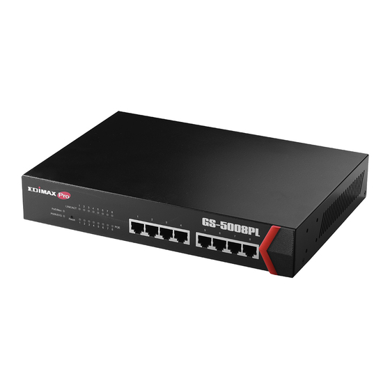
1.3 External Component Description 1.3.1 Front Panel The front panel of the Switch consists of 8 x 10/100/1000Mbps RJ-45 ports, and a series of LED indicators as shown as below. Front Panel 10/100/1000Mbps RJ-45 ports (1~8): Designed to connect to the device with a bandwidth of 10Mbps, 100Mbps or 1000Mbps. Each has a corresponding 10/100/1000Mbps LED. - Page 5 LED Indicators The following chart shows the LED indicators of the Switch along with explanation of each indicator. Power/System: Green LED Off: power off or fail On: power on Blinking: system booting up PoE Max: Green LED ...
-
Page 6: Rear Panel
1.4 Package Contents Before you start using this product, please check if there is anything missing in the package, and contact your dealer to claim the missing item(s): GS-5008PL POE Web Smart Switch Quick Installation Guide ... -
Page 7: Chapter 2 How To Login The Switch
Chapter 2 Connect & Login 2.1 Switch to End Node Use a standard Cat.5/5e Ethernet cable (UTP/STP) to connect the Switch to end nodes as shown below. Switch ports will automatically adjust to the characteristics (MDI/MDI-X, speed, duplex) of the device to which is connected. -
Page 8: How To Login The Switch
2.2 Login Open a web browser and go to the switch’s IP address. The default IP address is 192.168.2.2. Your computer’s IP address must be in the same subnet as the switch. For the default IP address this is any IP address in the range 192.168.2.x (x = 3 –... -
Page 9: Chapter 3 Switch Configuration
Chapter 3 Switch Configuration The PoE smart switch software provides rich layer 2 functionality for switches in your networks. This chapter describes how to use the web-based management interface (Web UI) to configure the switch’s features. The left column shows the configuration menu. The top row shows the switch’s current link status. -
Page 10: System
3.1 System View device information and status such as firmware version number, Device Name, MAC address, IP Address, Loop Status, PoE Status, etc. Use this screen to configure device name and ipv4 address. LABEL DESCRIPTION Model Name This field displays the model of the Switch. Device Name This field displays the descriptive name of the Switch for identification purposes. -
Page 11: Device Name Setup
3.1.1 Device Name Setup Go to System > Device Name Choose a descriptive name for identification purposes. This name consists of up to 20 characters; "a-z","A-Z","0-9" and hyphen and underscore are allowed. 3.1.2 IPv4 Address and Subnet Mask Setup The Switch needs an IP address for it to be managed over the network. The factory default in-band IP address is 192.168.2.1. -
Page 12: Management
3.2 Management Use this screen to manage firmware and your configuration files. Click Management in the navigation panel to open the following screen. BUTTON DESCRIPTION Reset Click Reset to clear all Switch configuration information you configured and return to the factory defaults. Reboot Click Reboot and then wait for the Switch to restart. -
Page 13: Port
3.3 Port To view port statistics, click Port in the web configurator menu. LABEL DESCRIPTION Port This identifies the Ethernet port. Link Status This field displays the speed (either 10Mbps, 100Mbps or 1000Mbps). This field displays Down if the port is not connected to any device. This field shows the number of transmitted bytes on this port. -
Page 14: Vlan
2 Bytes 3 Bits 1 Bit 12 bits Once the VLAN table is configured and maintained in GS-5008PL, frames will be handled by all operations of VLAN configuration. These operations include the stripping or adding of the IEEE 802.1Q tag. - Page 15 LABEL DESCRIPTION Port This identifies the Ethernet port. PVID This is the VLAN ID assigned to untagged frames that this port received. Apply Click Apply to save PVID changes to the non-volatile memory Maximum number of The maximum number of IEEE 802.1Q VLAN that can be created. IEEE 802.1Q VLAN VLAN ID This is the VLAN identification number that was configured in the IEEE 802.1Q...
-
Page 16: Port-Based Vlan
3.4.2 Port-Based VLAN Go to VLAN > Port-Based VLAN The port-based VLAN feature works as a filter, filtering out traffic destined to non-private domain ports. For each received frame, the forwarding table (FDB) resolves the DA and obtains a forwarding vector (list of ports to which the frame will be forwarded).The FDB then applies the VLAN filter to the forwarding vector, effectively masking out the non-private domain ports. -
Page 17: Trunking
3.5 Trunking Go to Trunking > LACP Link aggregation (trunking) is the grouping of physical ports into one logical higher-capacity link. You may want to trunk ports if for example, it is cheaper to use multiple lower-speed links than to under-utilize a high-speed, but more costly, single-port link. - Page 18 address. Select MAC SA & DA to distribute traffic based on a combination of the packet’s source and destination MAC addresses. Link Group Activity Switch TX LACP control packet Activity or Passive. Link Group Member The check box of port would be selected that the port added into Link Group successfully when refresh this web page.
-
Page 19: Qos
3.6 QoS GS-5008PL provide Quality of Service (QoS) feature. Two kinds of QoS mechanism are provided for traffic forwarding: port-based QoS and 802.1p QoS. Users can switch either of them by Web pages. When Quality of Service (QoS) feature is enabled, traffic will be forwarded according to predefined setting of port-based QoS or 802.1p QoS. - Page 20 Queue Go to QoS > IEEE 802.1P QoS Go to QoS > Disable QoS...
-
Page 21: Broadcast Storm Control
3.7 Broadcast Storm Control GS-5008PL provides a Rate Control feature. When the Rate Control feature is enabled, GS-5008PL provides Ingress/Egress traffic Rate Control per port for broadcast traffic type. Enable this feature to reduce broadcast packets in your network. Broadcast Storm Control > Broadcast Storm Control... -
Page 22: Loop Detect/Prevent
3.8 Loop Detect/Prevent GS-5008PL provides a Loop Protection feature for unmanaged environments. Two kinds of mechanism are available in the GS-5008PL, which are Loop Detection and Loop Prevention. Users can choose to enable Loop Detection or Loop Prevention. The Loop Discovery frame uses the system mac as source address. When the port receives the discovery frame and the source mac is the same as system mac, this will be determined as a loop. -
Page 23: Igmp Snooping
3.9 IGMP Snooping When the IGMP Snooping is enabled, the GS-5008PL will process IGMP control packets for multicast traffic forwarding. The switch will record information of IGMP v2 packets and maintain database for multicast traffic. Then multicast traffic will be forwarded according to the database. -
Page 24: Poe
3.10 POE The GS-5008PL provides a Power over Ehernet (PoE) manager feature. The IC of the PoE module is Microsemi PD69104B. The PoE module manager enables network devices to share power and data over a single cable. The PoE module is employed by both Ethernet switches and Midspans. -
Page 25: Password
3.11 Password To display Change Password page, click Password. Change Login User name and Password... -
Page 26: Logout
3.12 Logout If you want to logout of the system, click Logout . - Page 27 COPYRIGHT Copyright Edimax Technology Co., Ltd. all rights reserved. No part of this publication may be reproduced, transmitted, transcribed, stored in a retrieval system, or translated into any language or computer language, in any form or by any means, electronic, mechanical, magnetic, optical, chemical, manual or otherwise, without the prior written permission from Edimax Technology Co., Ltd.
-
Page 28: Federal Communication Commission Interference Statement
Federal Communication Commission Interference Statement This equipment has been tested and found to comply with the limits for a Class B digital device, pursuant to Part 15 of FCC Rules. These limits are designed to provide reasonable protection against harmful interference in a residential installation. -
Page 29: Eu Declaration Of Conformity
EU Declaration of Conformity English: This equipment is in compliance with the essential requirements and other relevant provisions of Directive 1995/5/EC, 2009/125/EC, 2006/95/EC, 2011/65/EC. Français: Cet équipement est conforme aux exigences essentielles et autres dispositions de la directive 1995/5/CE, 2009/125/CE, 2006/95/CE, 2011/65/CE. Čeština: Toto zařízení... -
Page 30: Declaration Of Conformity
Declaration of Conformity We, Edimax Technology Co., Ltd., declare under our sole responsibility, that the equipment described below complies with the requirements of the European R&TTE directives. Equipment: GS-5008PL PoE+ Web Smart Switch Model No.: GS-5008PL The following European standards for essential requirements have been followed:... - Page 31 Notice According to GNU General Public License Version 2 This product includes software that is subject to the GNU General Public License version 2. The program is free software and distributed without any warranty of the author. We offer, valid for at least three years, to give you, for a charge no more than the costs of physically performing source distribution, a complete machine-readable copy of the corresponding source code.
- Page 32 1. You may copy and distribute verbatim copies of the Program’s source code as you receive it, in any medium, provided that you conspicuously and appropriately publish on each copy an appropriate copyright notice and disclaimer of warranty; keep intact all the notices that refer to this License and to the absence of any warranty; and give any other recipients of the Program a copy of this License along with the Program.
- Page 33 License. Therefore, by modifying or distributing the Program (or any work based on the Program), you indicate your acceptance of this License to do so, and all its terms and conditions for copying, distributing or modifying the Program or works based on it. 6.
Need help?
Do you have a question about the GS-5008PL and is the answer not in the manual?
Questions and answers