Table of Contents
Advertisement
Quick Links
8863H-English_Manuals 3/14/15 12:58 PM Page 1
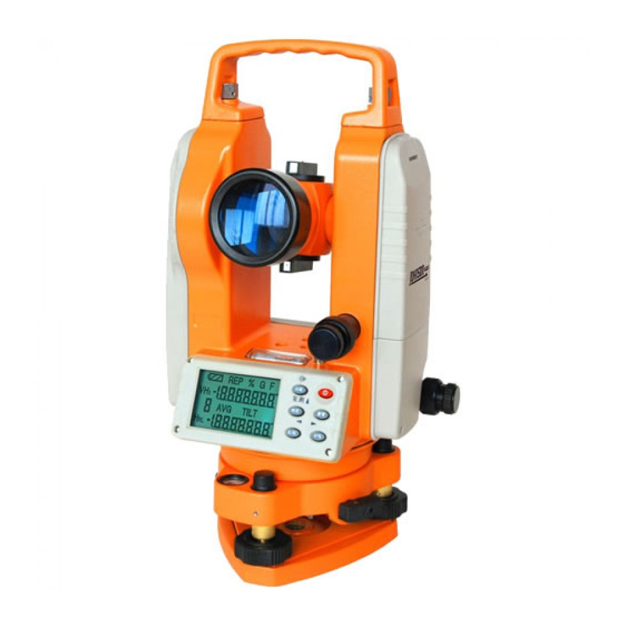
Electronic Digital Theodolite
with Laser
Model No. 40-6936
Instruction
Manual
Congratulations on your choice of this Electronic Digital Theodolite with
laser. We suggest you read this instruction manual thoroughly before
using the instrument. Save this instruction manual for future use.
This is a Class IIIa laser
tool and is manufactured
!
to comply with CFR 21,
parts 1040.10 and
1040.11 as well as
international safety rule
IEC 285.
©2015 Johnson Level & Tool - Rev. 1
1
Advertisement
Table of Contents

Related Manuals for Johnson 40-6936


Summary of Contents for Johnson 40-6936
- Page 1 Save this instruction manual for future use. This is a Class IIIa laser tool and is manufactured to comply with CFR 21, parts 1040.10 and 1040.11 as well as international safety rule IEC 285. ©2015 Johnson Level & Tool - Rev. 1...
-
Page 2: Table Of Contents
Description for Model 40-6936 Qty. Electronic Digital Theodolite with Laser Alkaline Battery Compartment (batteries not included) NiMH Rechargeable Battery Pack 3-7.5V Battery Adapter Rain Hood Adjustment Tools Instruction Manual with Warranty Card Hard-Shell Carrying Case ©2015 Johnson Level & Tool - Rev. 1... -
Page 3: Features And Functions
• Battery status indicator - no power surprises and allows for better planning • Automatic shutoff - conserves battery life when not in use - can be disabled if desired • Laser Plummet ©2015 Johnson Level & Tool - Rev. 1... -
Page 4: Safety Instructions
• Use only original Johnson ® parts and accessories purchased from your Johnson ® ® authorized dealer. Use of non-Johnson parts and accessories will void warranty. ©2015 Johnson Level & Tool - Rev. 1... -
Page 5: Location/Content Of Warning Labels
8863H-English_Manuals 3/14/15 12:58 PM Page 5 4. Location/Content of Warning Labels ©2015 Johnson Level & Tool - Rev. 1... -
Page 6: Location Of Parts/Components
Horizontal Clamp Operating Keys Tubular Vial Circular Vial Tripod Base Plate Battery Case Focusing Ring Eyepiece Telescope Fine Motion Laser Plummet On/off Knob Telescope Clamp Communication Port Tribrach Locking Leveling Screw Lever ©2015 Johnson Level & Tool - Rev. 1... -
Page 7: Operating Instructions
7. TILT - Tilt sensor 8. F - Function mode 9. G - Angle unit GON 10. % - Vertical slope in percent 11. REP - Repeated angle measurement mode 12. Battery power indication ©2015 Johnson Level & Tool - Rev. 1... - Page 8 Moving the cursor to the left Moving the cursor to the right Change the number indicated by the cursor Power key Zero the horizontal angle reading Change vertical angle to percent of grade Repeated angle measurement ©2015 Johnson Level & Tool - Rev. 1...
- Page 9 • Now center the instrument’s Circular Vial by carefully extending or shortening the tripod leg closest to the bubble. Note: Use only two legs. Repeat until alignment is within 6mm (1/4 inch) or less. ©2015 Johnson Level & Tool - Rev. 1...
- Page 10 Go back to the first position BC, and repeat until the bubble is centered in both positions. Then from position BC turn 180º to check the adjustment. If the bubble stays centered or within 1/4 division, you are level. ©2011 Johnson Level & Tool...
- Page 11 - y direction. Do not rotate the instrument. Recheck leveling and repeat until instrument is level and over the ground point at the same time. With practice, this becomes easier. ©2011 Johnson Level & Tool...
-
Page 12: Using The Product
Full power Effective battery Effective battery Weak voltage but still effective, suggest changing battery packs Powers off automatically after symbol blinks. Replace the battery pack or recharge it. Battery Strength ©2015 Johnson Level & Tool - Rev. 1... - Page 13 Place the projection on the bottom of the battery box into the slot on the instrument. Push the top of the battery box until it clicks into place. Battery Cover Battery Cover ©2015 Johnson Level & Tool - Rev. 1...
- Page 14 The reverse position refers to observation with the vertical circle being on the right. The mechanical errors can be offset by averaging the values measured in the normal and reverse positions. ©2015 Johnson Level & Tool - Rev. 1...
- Page 15 2. Press 0-set key once to set the reading of horizontal angle of target “A” at 0º00’00”. 3. Rotate the instrument clockwise and aim at the second target “B” to get the horizontal and vertical angle of target “B”. ©2015 Johnson Level & Tool - Rev. 1...
- Page 16 2. Press the HOLD key once to lock the value of the horizontal angle, the reading will flash. 3. Press the HOLD key again to unlock the reading. • The HOLD key has no effect to the vertical angle. ©2015 Johnson Level & Tool - Rev. 1...
- Page 17 Note: When vertical angle is converted to slope, the precision of the slope reading is two digits after the decimal. The value of slope is displayed only within a 45º (100%). When measure angle exceeds 100%, the percent will be shown as “----”. ©2015 Johnson Level & Tool - Rev. 1...
- Page 18 9. Repeat the last three steps according to measuring requirements. 10. If needed return back to normal angle measurement, press FUNC key, and then press the HOLD key. ©2015 Johnson Level & Tool - Rev. 1...
- Page 19 DEG, GON and MIL and can be chosen in the preliminary setting, or by following this procedure. Simultaneously press R/L and V/%, the angle measurement units will switch between DEG, GON and MIL. ©2015 Johnson Level & Tool - Rev. 1...
- Page 20 “Tilt” will appear on the display. If the instrument is inclined within +3º the tilt sensor can compensate the vertical angle. If the inclination is greater than + 3º the instrument will display “b”. ©2015 Johnson Level & Tool - Rev. 1...
- Page 21 Laser (Plummet) With the instrument turned on, turn on the laser plummet on/off knob turning it all the way clockwise. The laser plummet will turn off when the instrument is turned off. ©2015 Johnson Level & Tool - Rev. 1...
- Page 22 Setting 2 Vertical Angle mode for vertical angle vertical angle zenith angle height angle Setting 0 Setting 1 Tilt sensor Set tilt function Set data transmission Setting 0 Setting 1 Data transmission function ©2015 Johnson Level & Tool - Rev. 1...
- Page 23 • Minimal Resolution Reading: 5" (40-6936) • Sound Function: OFF • Angle Display Unit: 360º • Automatic Shut Off: OFF • Measuring-Mode for Vertical Angle: Vertical Angle • Tilt Sensor: OFF • Data Transmission Function: OFF ©2015 Johnson Level & Tool - Rev. 1...
-
Page 24: Error Display
• Lift the instrument by hand, and aim the positioning block to the notch on the base plate. Mount the instrument on the base plate carefully. • Tighten the clamp knob on Positioning block the base plate. Notch Tribrach Locking Level ©2015 Johnson Level & Tool - Rev. 1... -
Page 25: Self-Check & Fine Calibration
• Using the bubble adjustment screws and adjustment pin, move the bubble towards the tube center for half of the error. • Turn the leveling screw to correct the other half of the error so that the bubble is centered. ©2015 Johnson Level & Tool - Rev. 1... - Page 26 Perpendicularity of Vertical Crosshair Reticle of Telescope Checking • Mount the instrument on the tripod and level it carefully. • Set a target point, A, 50 meters away from the instrument, aim the telescope at point A . ©2015 Johnson Level & Tool - Rev. 1...
- Page 27 • Tighten these four set screws equally and observe whether any transversal deviation appears when point A moves along the vertical hair. If not, the adjustment is over. • Assemble back the protective cover to its original position. ©2015 Johnson Level & Tool - Rev. 1...
- Page 28 • Rotate the telescope 180º around the horizontal axis again. Aim at the target C. Target C should be the same with target B. • If not coincident, adjustment is necessary. ©2015 Johnson Level & Tool - Rev. 1...
- Page 29 • After mounting and leveling the instrument, position the direction of the telescope with a line between the center of the instrument and any of its foot screws. Then tighten the horizontal braking handwheel. ©2015 Johnson Level & Tool - Rev. 1...
- Page 30 • If upright angle is in the zenith angle mode, then i=(L+R-360°)/2. If upright angle is in the vertical angle mode, then i=(L+R-180°)/2 or i=(L+R-540°)/2 • If the specification errors |i|° ≤ 10", 0 reset of the upright plate specification is necessary. ©2015 Johnson Level & Tool - Rev. 1...
- Page 31 • Send the instrument to an authorized repair facility for repairs after operations are repeated many times without any effect. ©2015 Johnson Level & Tool - Rev. 1...
- Page 32 “G” – Angle In Gon (400 Gon) “M” – Angle In Mil (6400 Mil) “%”– Slope Angle (-100% ~ +100%) The transmission angle value keeps consistent with the display value on the LCD. ©2015 Johnson Level & Tool - Rev. 1...
-
Page 33: Technical Specifications
Tubular Vial 30"/2mm Circular Vial 8'/2mm Compensator Tilt Sensor Upright Angle Automatic Compensation Compensation Range ±3' Laser Laser Wavelength 635nm±10 Laser Classification Class IIIa Interior Range 600' (200m) Exterior Range 100' (40m) ©2015 Johnson Level & Tool - Rev. 1... - Page 34 16 hours Working Environment Temperature Range -4°F to +104°F (-20°C to +40°C) Size and Weight Outside Dimension 6.29" x 5.90" x 12.99" (160x150x330mm) Weight 10.14 lbs (4.6kg) Center Screw Thread 5/8" - 11 ©2015 Johnson Level & Tool - Rev. 1...
-
Page 35: Care And Handling
• Store the instrument in a dust-free area with low humidity. • A bag of silica gel dryer is included with each instrument. • Always remove the batteries when the instrument is not being used for a long time. ©2015 Johnson Level & Tool - Rev. 1... -
Page 36: Product Warranty
8863H-English_Manuals 3/14/15 12:59 PM Page 36 11. Product Warranty Johnson Level & Tool offers a three year limited warranty on each of its products. You can obtain a copy of the limited warranty for a Johnson Level & Tool product by contacting Johnson Level & Tool's Customer Service Department, as provided below, or by visiting our web site at www.johnsonlevel.com. -
Page 37: Warranty Registration
NO WARRANTY. If you need any assistance in locating any accessories, please contact our Customer Service Department. In the U.S., contact Johnson Level & Tool’s Customer Service Department at 888-9-LEVELS. In Canada, contact Johnson Level & Tool’s Customer Service Department at 800-346-6682. -
Page 38: Trouble Shooting
• If the theodolite is out of calibration, follow the calibration procedure in the user manual. • If the theodolite will not calibrate, contact an authorized Johnson Service Center or Johnson Level & Tool's Customer Service Center. • If the keypad or vertical measuring mode will not work, rotate the telescope 360°...
Need help?
Do you have a question about the 40-6936 and is the answer not in the manual?
Questions and answers