Table of Contents
Advertisement
Advertisement
Table of Contents

Related Manuals for Ruida Technology RDLC320


Summary of Contents for Ruida Technology RDLC320
- Page 1 RDLC320 Controller User Manual Shenzhen RuiDa Technology CO., LTD Tel: 86- 0755-26066687 Fax: 86-0755-26982287 Web: www.rd-acs.com E-Mail: support@rd-acs.com Add: 1B-1, Building 5, Tian'an Nanyou Industry Area, Dengliang Road, Nanshan District, Shenzhen, P.R.C.
-
Page 2: Table Of Contents
Chapter 7 Examples of IO-port Wiring..............20 Input Port......................20 Output Port..................... 21 Chapter 8 Man-machine Interface Operating Instruction........22 Introduction to the Main Interface..............22 Introduction to the Keys.................23 Chapter 9 Manufacturer/User Parameters Explanation........34 © 2016 Ruida Technology. All Rights Reserved. - Page 3 10.1 Single Controller Connects to PC with Single NIC..........41 10.2 Single Controller Connects to PC with Multi-NIC...........42 10.3 Multi-controller Connects to PC via Concentrator........... 43 10.4 Multi-controller Connects to PC via Concentrator, Concentrator connects to Router........................44 © 2016 Ruida Technology. All Rights Reserved.
-
Page 4: Copyright Declaration
2. Ruida Technology is entitled to increase or reduce and modify the products and functions of this product stated herein as well as amend any documents attached to this product, without prior notification. -
Page 5: Chapter 1 Overview
Chapter 1 Overview Briefing RDLC320 system is a new generation system for control of laser engraving and cutting, which is developed by RD Technology, Ltd. In addition to high hardware stability, high voltage or static electricity rejection, and friendly man-machine... -
Page 6: Comparison Of Controller Performance
Key Speed Fixed Fixed Configurable Axles 3 (Z axes is configurable to flat or feeding axes) Encryptio Null Encryption based Real-time clock battery n Feature on the PC time integrated for hardware encryption © 2016 Ruida Technology. All Rights Reserved. -
Page 7: Chapter 2 Installation Dimension
RDLC320 Controller User Manual Chapter 2 Installation Dimension Installation dimension of IO Interface Board The unit of all sizes is millimeter (mm) and the size accurate to 0.1mm. 4-M3 Stud rivet, 4 high Figure: 2.1-1 © 2016 Ruida Technology. All Rights Reserved. -
Page 8: Panel Dimension
RDLC320 Controller User Manual Panel Dimension The unit of all sizes is millimeter (mm) and the size accurate to 0.1mm. 4-M3 Stud rivet, 10 high 4-M3 Stud rivet, 8 high Figure: 2.2-1 © 2016 Ruida Technology. All Rights Reserved. -
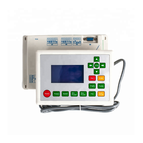
Page 9: Chapter 3 Pictures And Interfaces
Picture of Main Board For more detailed of pin description, see the Chapter 4: Description of Interface Signal for IO board. Figure: 3.1-1 IO Picture of Board Picture of Panel Figure: 3.2-1 Picture of Panel © 2016 Ruida Technology. All Rights Reserved. -
Page 10: Chapter 4 Description Of Io Board Interface Signal
O 24V External power output (If the interface of main power source is powered with 24V power supply, this pin should be 24V; if it is powered with 36 V power supply, this pin © 2016 Ruida Technology. All Rights Reserved. -
Page 11: 3-Axle Spacing And Special Input Interface Cn3/Cn4
LmtZ- The spacing from axle Z- and Z to 0 coordinate LmtZ+ The spacing from axle Z- and Z to max. coordinate O 5V External power source + 5V (output) © 2016 Ruida Technology. All Rights Reserved. -
Page 12: X/Y/Z-Axle Motion Drive Interface
In such a case, the connection between this axle and the motor driver can be broken first (otherwise the controller cannot be detected to the spacing so as to lead to the collision of this axle), © 2016 Ruida Technology. All Rights Reserved. -
Page 13: Laser Power Control Interface Cn6/Cn7
Please make corrective choice of laser type. After the option for laser type is modified, the controller should be reset so that the modification can be effected after resetting. Prompt © 2016 Ruida Technology. All Rights Reserved. -
Page 14: Water Protect Input Interface Cn5
If the water protector 2 is not enabled, the controller will not detect the input port of water protector 2 and the user not connect the water protector 2. L-IN3 General input with the function reserved. Laser power 5V positive (output) © 2016 Ruida Technology. All Rights Reserved. -
Page 15: Chapter 5 Examples Of Laser Power Interface
RDLC320 Controller User Manual Chapter 5 Examples of Laser Power Interface Digital Laser Power Supply of Glass Tube Analog Laser Power Supply of Glass Tube © 2016 Ruida Technology. All Rights Reserved. -
Page 16: Rf Co2 Laser
RDLC320 Controller User Manual RF CO2 Laser © 2016 Ruida Technology. All Rights Reserved. -
Page 17: Chapter 6 Examples Of Driver Interface For Step-Servo Motor
Figure: 6.1-1 Four Inputs, Independent Figure: 6.1-2 Three Inputs, Input Signal of Driver Common-anode Input Signal of Driver © 2016 Ruida Technology. All Rights Reserved. -
Page 18: Valid Rising Edge For Pulse Signal
Technology Co., Ltd., Shenzhen Baishan Mechatronics Co., Ltd., Beijing Jektechnology Co., Ltd. and the like. The input signals for some motor drivers are independent and some of common anode. (1). The drivers with independent input signals include D921 and WD3-00X from © 2016 Ruida Technology. All Rights Reserved. - Page 19 (2). The drivers with common-anode input signals, such as YKA2304ME from Shenzhen YAKO Automation Technology Co., Ltd., Q2HB34MB and Q2HB44MA(B) from Shenzhen Baishan Mechatronics Co., Ltd. Figure: 6.3-3 Three Inputs, Valid Falling Edge and Common Anode Connection © 2016 Ruida Technology. All Rights Reserved.
-
Page 20: Chapter 7 Examples Of Io-Port Wiring
RDLC320 Controller User Manual Chapter 7 Examples of IO-port Wiring Input Port The input connection at X/Y minus spacing is exampled. Figure: 7.1-1 Example of Input-port Connection © 2016 Ruida Technology. All Rights Reserved. -
Page 21: Output Port
RDLC320 Controller User Manual Output Port Figure: 7.2-1 Example of Output-port Connection © 2016 Ruida Technology. All Rights Reserved. -
Page 22: Chapter 8 Man-Machine Interface Operating Instruction
Max Power:XX.X% Run Speed:XXX mm/s System Paused: 00.12.40 Figure: 8.1-2 Running Interface (display time selected file: hour/minute/second) File:XX File Number:XXXX Max Power:XX.X% Run Speed:XXX mm/s System Run: 00.12.40 Figure: 8.1-3 22 / 45 © 2016 Ruida Technology. All Rights Reserved. -
Page 23: Introduction To The Keys
8.1-4, you can press any keys on the keyboard. On the interfaces shown in Figure 8.1-2 and 8.1-3, some keys can’t respond. File:XX File Number:XXXX Max Power:XX.X%/ XX.X% Run Speed:XXX mm/s System Idle: 25/12/2010 Figure: 8.1-5 Introduction to the Keys (1) Reset key Reset 23 / 45 © 2016 Ruida Technology. All Rights Reserved. - Page 24 If the time is set to zero, then the outputting time is the time when the “Laser” key is pressed, that is to say, press this key for outputting and release it for 24 / 45 © 2016 Ruida Technology. All Rights Reserved.
- Page 25 Max. Power 2 XX.X% Figure: 8.2-3 Enter (4) Min. Power key Min. Power The display interface and the operating mode of this key are similar to those of the “MaxPower” key. 25 / 45 © 2016 Ruida Technology. All Rights Reserved.
- Page 26 Press the “File” key in the idle system interface or the work finished interface and two pages will appear. Press the “Up” and “Down” key and you can turn the pages up and down. The interface will show the following in turn: 26 / 45 © 2016 Ruida Technology. All Rights Reserved.
- Page 27 “Enter” key to enter the submenu. On selecting “Memory File” or “USB File”, if the by visitor has no files, the interface will show the 27 / 45 © 2016 Ruida Technology. All Rights Reserved.
- Page 28 The file name that has only English letters and digits will not show when they are copied to the controller. The files copied from the controller to USB will be placed under the root directory of USB. 28 / 45 © 2016 Ruida Technology. All Rights Reserved.
- Page 29 In addition to being used for modifying parameters and moving the cursor as abovementioned, the directional keys can be used to move the kinematic axis under such three interfaces as idle, suspended system or work finished interface. Under such 29 / 45 © 2016 Ruida Technology. All Rights Reserved.
- Page 30 Z-axle Move Axles Reset+ Inch Setting+ Laser Setting+ Figure: 8.2-8 Origin Setting+ Set to Default Para. Load Default Para. Auto Focusing Langue+ Figure: 8.2-9 30 / 45 © 2016 Ruida Technology. All Rights Reserved.
- Page 31 4) When “Origin setting” is selected, it will show below: Multiple Origins: No/Yes Set as Origin1 Set as Origin2 Set as Origin3 Figure: 8.2-11 Set as Origin4 Next Origin 0 Origin Enable + Figure: 8.2-12 31 / 45 © 2016 Ruida Technology. All Rights Reserved.
- Page 32 You can return to the previous menu by press the Enter key. 7) When the cursor stops at “Auto Focusing”, press the Enter key to search for 32 / 45 © 2016 Ruida Technology. All Rights Reserved.
- Page 33 Esc key to return the prior menu. 8) The item “Langue” helps you to select a appropriate langue which is displayed on the panel. 33 / 45 © 2016 Ruida Technology. All Rights Reserved.
-
Page 34: Chapter 9 Manufacturer/User Parameters Explanation
Jump-off Speed: it means the speed of the motion axis in direct start from the idle condition. If this value is excessively large, it will make the motor lose steps, jar and even squeak; if small, it 34 / 45 © 2016 Ruida Technology. All Rights Reserved. - Page 35 Laser Configuration: single laser and double lasers are available for selection and configured as the laser-tube quantity provided by the manufacturer. Laser Type: glass tube, RF laser (not pre-ignition) and RF laser (pre-ignition) are available for selection. 35 / 45 © 2016 Ruida Technology. All Rights Reserved.
- Page 36 Transmission Mode: generally choose “Belt + step motor”, the control algorithm will be changed a little when other types are selected. Z-axis Function: “platform” and “feeding axis” are optional. 36 / 45 © 2016 Ruida Technology. All Rights Reserved.
-
Page 37: User Parameters
Cutting Acceleration: it means the highest acceleration value in the whole cutting process. 37 / 45 © 2016 Ruida Technology. All Rights Reserved. - Page 38 If so, the setting will become ineffective and the system will automatically cover the parameters with the axis parameters. Prompt (3) Reset Parameters Reset Speed: it means the speed of X/Y-axis linkage reset to the origin. 38 / 45 © 2016 Ruida Technology. All Rights Reserved.
- Page 39 The previous work is completed and delayed the value, the feeding axis begins to move. During the period of delay, it is convenient to feeding and select material for 39 / 45 © 2016 Ruida Technology. All Rights Reserved.
- Page 40 Backlash Y: The backlash of Y-axis, set the value according to the actual machine, accurate to 1 um, if this value is not 0, the control system will make compensation for backlash. 40 / 45 © 2016 Ruida Technology. All Rights Reserved.
-
Page 41: Chapter 10 Controller To Pc With Single Nic
Set the work mode to be ETHERNET on the panel. And then set the controller IP address between 192.168.001.100-192.168.001.149 Step 2: Set the IP address in the PC. The IP address is between 192.168.001.2-192.168.001.049. See picture1-1. Picture1-1 PC IP configuration 41 / 45 © 2016 Ruida Technology. All Rights Reserved. -
Page 42: Single Controller Connects To Pc With Multi-Nic
NIC configuration interface. Then input the password (default is Admin) Set the router IP address to be 192.168.2.1(make sure the IP to difference with other routers) (2) Get the router DNS Record the DNS server. 42 / 45 © 2016 Ruida Technology. All Rights Reserved. -
Page 43: Multi-Controller Connects To Pc Via Concentrator
Different IP address should be configured for each controller. But all of the IP address should be set between 192.168.001.100-192.168.001.149 (3) Set the PC IP address between 192.168.001.2-192.168.001.049. 43 / 45 © 2016 Ruida Technology. All Rights Reserved. -
Page 44: Router
Different IP address should be configured for each controller. But all of the IP address should be set between 192.168.001.100-192.168.001.149 Configured step please reference to Single Controller Connects to PC with Multi-NIC 44 / 45 © 2016 Ruida Technology. All Rights Reserved. - Page 45 RDLC320 Controller User Manual Thank you very much for using the product from Shenzhen RuiDa Technology! All parts of this manual description, all rights reserved by Shenzhen RuiDa Technology Co., Ltd. Without our permission, any company or individual shall not reprint, copy or distribute the content related to this product manual.
Need help?
Do you have a question about the RDLC320 and is the answer not in the manual?
Questions and answers