Table of Contents
Advertisement
Quick Links
Advertisement
Table of Contents

Related Manuals for Audio Technica ARTIST ELITE 4000


Summary of Contents for Audio Technica ARTIST ELITE 4000
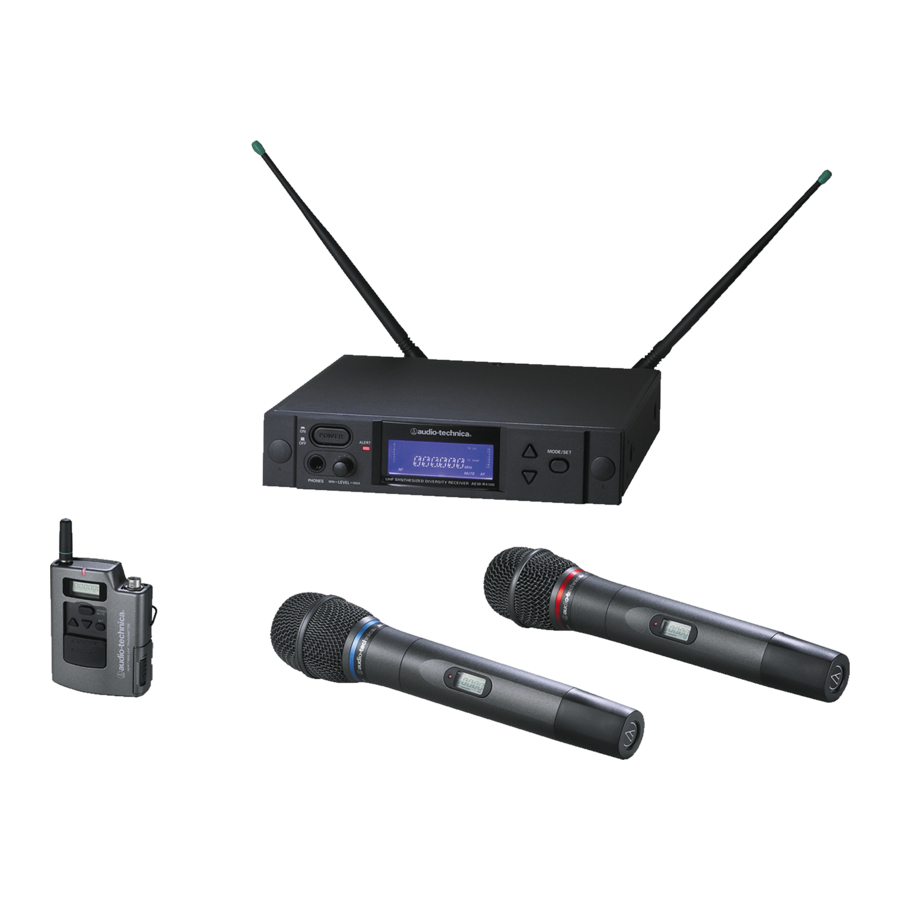
- Page 1 4000 & 5000 Series Professional UHF Wireless Systems Installation and Operation...
- Page 2 Professional UHF Wireless Systems Installation and Operation This device complies with part 15 of the FCC Rules. Operation is subject to the condition that this device does not cause harmful interference. This device complies with INDUSTRY CANADA R.S.S. 210, en conformité...
-
Page 3: Table Of Contents
Introduction ...6 System Configurations ...6 Operating Frequencies ...7 Receivers ...7 Multi-channel Systems ...8 Transmitters ...8 Receiver Installation...8 Location ...8 Output Connections...8 Antennas ...8 Antenna Power ...8 Front-mount Antennas ...9 Headphone Jack ...9 Power Connections ...9 “Link” Connections ...9 Ethernet Connections (AEW-R5200 only) ...10 Receiver Controls and Functions ...10 AEW-R5200 Front Panel Controls and Functions ...10 AEW-R5200 Rear Panel Controls and Functions ...11... - Page 4 UniPak Transmitter Functions (Chart) ...21 Handheld Transmitter Functions (Chart) ...21 Transmitter Setup...22 Battery Selection and Installation ...22 Battery Condition Indicator ...22 UniPak Transmitter Input Connection ...23 UniPak Transmitter Antenna ...23 Handheld Transmitter Antenna ...23 UniPak Transmitter Mounting Clip ...23 System Operation ...24 Selecting/Setting Receiver Frequency...24 Setting Receiver Frequency Manually ...24 Setting Receiver Frequency Using IntelliScan...
-
Page 5: Introduction
Each model must extend the performance of a sound system, not limit it. Artist Elite Receivers Artist Elite 4000 Series and 5000 Series wireless systems by Audio-Technica share a range of transmitters in common, both body-pack and handheld types. The difference between the... -
Page 6: Operating Frequencies
(patents pending). As a result, Artist Elite Series transmitters and receivers must be used together in Tx-Rx pairs and should not be mixed with components from other Audio-Technica wireless systems, or with those of other manufacturers. All Artist Elite Series components feature soft-touch controls for quick, easy access to a formidable range of functions;... -
Page 7: Multi-Channel Systems
Ethernet-based monitoring and control (AEW-R5200): Some wireless systems on the market offer remote control/monitoring of the receiver via a serial interface, but the Audio-Technica AEW-R5200 receiver takes this a significant step further by including control over IP using standard networking protocol and Ethernet interfacing. -
Page 8: Front-Mount Antennas
Front-mount Antennas AEW-R4100: Provision has been made to move the antenna jacks from the rear to the front of the receiver. However, because this involves opening the receiver case and exposing AC power circuitry, instructions are not included in this manual. A qualified service technician must perform this modification. -
Page 9: Aew-R5200 Front Panel Controls And Functions (Figure C)
Ethernet connections (AEW-R5200): An RJ-45 jack on the rear panel of each AEW-R5200 provides an Ethernet 10 BaseT data/control connection from both of its channels to an external computer system. Data monitored includes actual, real-time “RF” and “AF” levels for receiver channels with direct Ethernet connections to the associated computer. -
Page 10: Aew-R5200 Rear Panel Controls And Functions
Figure D AEW-R5200 Receiver Rear Panel INSTRUMENT 0/-6/-12 ANT. B ATTN (dB) EXTERNAL OUTPUT MUTE (BAL) 15 16 17 Rear Panel Controls and Functions (Fig. D) 14 ANTENNA INPUT JACK: BNC-type antenna connector for Tuner “B.” Attach the antenna directly, or extend it with a low-loss antenna cable. -
Page 11: Aew-R4100 Front Panel Controls And Functions
Figure E AEW-R4100 Receiver Front Panel POWER ALERT UHF SYNTHESIZED DIVERSITY RECEIVER AEW-R4100 PHONES MIN– LEVEL –MAX 34 35 Front Panel Controls and Functions (Fig. E) 32 POWER SWITCH: Press Power switch in and the receiver readouts will light. 33 HEADPHONE OUTPUT: "... -
Page 12: Instrument Output Jack
Figure F AEW-R4100 Receiver Rear Panel Rear Panel Controls and Functions (Fig. F) 40 ANTENNA INPUT JACK: BNC-type antenna connector for Tuner “B.” Attach the antenna directly, or extend it with a low-loss antenna cable. See the “Antennas” section on page 8 for more details. -
Page 13: Common Receiver Controls
Receiver Controls Power On/Off Press the power switch to turn the receiver on. After a short power-up sequence, the display shows the operating frequency and the alert light is illuminated (if no active transmitters are present on this frequency). The receiver may also display a system position (i.e., “MASTER”, “SLV-#”) or an assigned transmitter or receiver name (if this feature has been set up—the display recalls the setting from the last time power... -
Page 14: Receiver Controls And Functions
Saving to a different user PRESET# location To store settings to a different user preset location, hold the Mode/Set button. The receiver shows “STORE XXXXXX” (where XXXXXX indicates the loaded preset’s name). Touch the Up/Down buttons to scroll to another preset location (the display shows the user-defined name for each location, or “PRESET#”... -
Page 15: Meter Hold
Meter Hold When activated (“METER HOLD”), this function permits the bar meters in the LCD window to capture and display the highest- level “AF” audio modulation (a solid bar) and the lowest-level “RF” signal (a flashing bar) received from the transmitter. This is particularly useful when setting up the system initially, performing a sound-check, or diagnosing operating problems. -
Page 16: Receiver Functions (Chart)
To load (recall) a Preset: 1. Touch the Mode/Set button once to move to Menu mode. 2. Touch the Up arrow twice. LCD top line shows “PRESET.” 3. Touch the Mode/Set button once. “LOAD” (or “STORE”) appears in the LCD. 4. -
Page 17: Transmitter Controls And Functions
Refer to Figures H through Q for an overview of transmitter functions and controls. Touch: A momentary press of the Mode/Set button. It is used to enter Menu mode, to enter Edit mode, or to Escape without making any changes to current settings. Hold: A press and hold (about two seconds) of the Mode/Set button. -
Page 18: Power/Mute Locks
Audio Input Selector The UniPak ™ body-pack transmitter provides input connections for both low-impedance (Lo-Z) microphones and high- impedance (Hi-Z) instruments. A wide range of Audio-Technica Wireless Essentials ® microphones and cables is available pre-terminated with the appropriate professional latching connector. -
Page 19: Preset/Default Settings
Preset/Default Settings A “PRESET” selection in the menu permits the storing of up to five different user-definable configurations. Customized names, using letters, numbers and symbols, can also be created and stored for Presets 1–5. In addition, a Default (“DEF”) choice permits returning all transmitter functions to their factory- default settings. -
Page 20: Unipak Transmitter Functions (Chart)
Transmitter Controls and Functions UniPak Transmitter Functions Function Menu Default Value LM Frequency Lowest in band † 200 discrete frequencies LM RF Power RF LOW LM Audio Input Level +6 dB LM Power/Mute Locks NO.LOC LM Input Select LM Preset Configurations PRESET LM LOAD: LM STORE: PRSET1... -
Page 21: Transmitter Setup
Battery Selection and Installation Each transmitter uses two 1.5V AA batteries, not included. Alkaline type is recommended. Always replace both batteries. Make certain the transmitter power is Off before replacing batteries. UniPak ™ Transmitter Battery Installation 1. Open the battery compartment door by sliding the catch down (Figure L). -
Page 22: Unipak Transmitter Input Connection
Connect an audio input device (microphone or guitar cable) to the audio input jack on the bottom of the transmitter. A number of Audio-Technica professional microphones and cables are available separately, pre-terminated with a UniPak input connector (see “Optional System Accessories” on page 28). -
Page 23: System Operation
Artist Elite wireless receivers and transmitters are extremely versatile components with many operating features and functions, some of which are not obvious. As a result, we suggest the following approaches to assure a “comfort level” with any new equipment: 1. Begin using a single receiver/transmitter pair at their Default (“DEF”) settings, to become familiar with equipment functions and operation before doing any customizing. -
Page 24: Setting Receiver Frequency Using Intelliscan
Figure R Group 1 Group 2 Group 3 Note: An asterisk in two or more locations indicates this frequency is in more than one group. Setting Receiver Frequency Using IntelliScan Single-receiver systems (either an AEW-R4100 or an AEW-R5200): Turn down the AF level of the associated mixer or amplifier. Make certain that any AEW transmitters are turned off. -
Page 25: Setting Transmitter Frequency
If you need assistance with operation or frequency selection, please contact your dealer or the Audio-Technica professional division. Extensive information on using wireless microphones is also available on the Audio-Technica Web site at www.audio-technica.com. ™ : Choices are +12 dB to –6 dB in 2 dB... -
Page 26: Specifications
OVERALL SYSTEM UHF Operating Frequency Band C: 541.500 to 566.375 MHz Band D: 655.500 to 680.375 MHz Number of Channels 200 total per band Frequency Stability ±0.005%, Phase Lock Loop frequency control Modulation Mode Normal Deviation ±5 kHz Operating Range 300' typical Operating Temperature Range 41°... -
Page 27: Optional System Accessories
WIRELESS ESSENTIALS ™ MICROPHONES AND CABLES All Wireless Essentials accessories are terminated for use with AEW-T1000 and other UniPak ™ transmitters. AT829cW Miniature cardioid condenser lavalier microphone. Includes clothing clip and windscreen. MT830cW Subminiature omnidirectional condenser lavalier microphone. Includes clothing clip and windscreen. MT830cW-TH “Theater”... -
Page 28: Artist Elite Wireless Operating Frequencies/Groups
Artist Elite Series UHF Wireless Operating Frequencies TV Ch. 542.000 542.125 543.000 543.125 544.000 544.125 545.000 545.125 546.000 546.125 547.000 547.125 548.000 548.125 549.000 549.125 550.000 550.125 551.000 551.125 552.000 552.125 553.000 553.125 554.000 554.125 555.000 555.125 556.000 556.125 557.000 557.125 558.000 558.125... - Page 29 Artist Elite Series Wireless Operating Frequencies Band C Group 1 TV Ch. Frequency - MHz (None) 542.750 543.000 545.500 546.000 547.125 547.375 549.500 549.750 550.375 550.625 557.250 557.500 558.750 559.250 559.500 562.000 562.250 563.375 563.625 566.000 566.250 Band D Group 1 TV Ch.
-
Page 30: Serial Number Log
For future reference, please record your system information here: Receivers: AEW-R4100 AEW-R5200 Transmitters: AEW-T1000 AEW-T3300 AEW-T4100 AEW-T5400 AEW-T6100 S/N_____ _____ _____ _____ _____ _____ _____ Serial Number appears on the FCC label on the bottom of the receiver. S/N_____ _____ _____ _____ _____ _____ _____ Serial Number appears on the FCC label on the bottom of the receiver. -
Page 31: Visit Our Website
One-Year Limited Warranty Audio-Technica professional wireless systems purchased in the U.S.A. are warranted for one year from date of purchase by Audio-Technica U.S., Inc. ( A. T .U.S.) to be free of defects in materials and workmanship. In event of such defect, product will be repaired promptly without charge or, at our option, replaced with a new product of equal or superior value if delivered to A.
Need help?
Do you have a question about the ARTIST ELITE 4000 and is the answer not in the manual?
Questions and answers