Advertisement
Table of Contents
- 1 Table of Contents
- 2 Warning Decal Placement
- 3 Important Precautions
- 4 Before You Begin
- 5 Assembly
- 6 How to Use the Chest Pulse Sensor
- 7 Operation and Adjustment
- 8 How to Fold and Move the Treadmill
- 9 Troubleshooting
- 10 Exercise Guidelines
- 11 Part List
- 12 Exploded Drawing
- 13 Ordering Replacement Parts
- 14 Recycling Information
- Download this manual
Model No. NETL12710.2
Serial No.
Write the serial number in the space
above for reference.
Serial Number
Decal
QUESTIONS?
If you have questions, or if there are
missing parts, please contact us:
UK
Call: 08457 089 009
From Ireland: 053 92 36102
Website: www.iconsupport.eu
E-mail: csuk@iconeurope.com
Write:
ICON Health & Fitness, Ltd.
c/o HI Group PLC
Express Way
Whitwood, West Yorkshire
WF10 5QJ
UK
AUSTRALIA
Call: 1-800-237-173
E-mail:
australiacc@iconfitness.com
CAUTION
Read all precautions and instruc-
tions in this manual before using
this equipment. Save this manual
for future reference.
USERʼS MANUAL
www.iconeurope.com
Advertisement
Table of Contents

Related Manuals for NordicTrack T14.0 NETL12710.2


Summary of Contents for NordicTrack T14.0 NETL12710.2
- Page 1 USERʼS MANUAL Model No. NETL12710.2 Serial No. Write the serial number in the space above for reference. Serial Number Decal QUESTIONS? If you have questions, or if there are missing parts, please contact us: Call: 08457 089 009 From Ireland: 053 92 36102 Website: www.iconsupport.eu E-mail: csuk@iconeurope.com Write:...
-
Page 2: Table Of Contents
Apply the decal in the location shown. Note: The decals may not be shown at actual size. NordicTrack is a registered trademark of ICON IP, Inc. -
Page 3: Important Precautions
IMPORTANT PRECAUTIONS WARNING: To reduce the risk of serious injury, read all important precautions and in- structions in this manual and all warnings on your treadmill before using your treadmill. ICON as- sumes no responsibility for personal injury or property damage sustained by or through the use of this product. - Page 4 20. Do not attempt to raise, lower, or move the treadmill, and before performing the mainte- treadmill until it is properly assembled. (See nance and adjustment procedures described in ASSEMBLY on page 6, and HOW TO FOLD this manual. Never remove the motor hood un- AND MOVE THE TREADMILL on page 25.) less instructed to do so by an authorized ser- You must be able to safely lift 45 lbs.
-
Page 5: Before You Begin
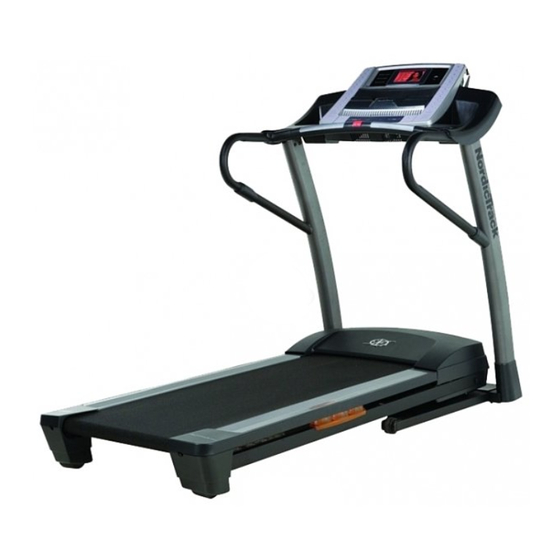
BEFORE YOU BEGIN Thank you for selecting the revolutionary NordicTrack ing this manual, please see the front cover of this man- ® T14.0 treadmill. The T14.0 treadmill offers an impres- ual. To help us assist you, please note the product sive selection of features designed to make your work- model number and serial number before contacting us. -
Page 6: Assembly
ASSEMBLY Use the drawings below to identify the assembly hardware. The number in parentheses below each drawing is the key number of the part, from the PART LIST near the end of this manual. The number after the parentheses is the quantity needed for assembly. Note: Some small parts may have been preassembled. To avoid dam- aging parts, do not use power tools for assembly. - Page 7 Assembly requires two persons. Set the treadmill in a cleared area and remove all packing materials. Do not dispose of the packing materials until assembly is completed. Note: The underside of the treadmill walking belt is coated with high-performance lubricant. During shipping, some lubricant may be transferred to the top of the walking belt or the shipping carton.
- Page 8 3. Identify the Right Upright (83), which is marked with a “Right” sticker. Have a second person hold the Right Upright near the Base (94). See the inset drawing. Tie the wire tie in the Right Upright (83) securely around the end of the Upright Wire (85).
- Page 9 5. With the help of a second person, carefully tip the treadmill onto its right side. Partially fold the Frame (55) so that the treadmill is more stable; do not fully fold the Frame yet. Insert a 3/8" x 5 1/2" Patch Bolt (7), a 3/8" x 3 3/4"...
- Page 10 7. Attach the Frame Crossbar (109) to the Frame (55) with two 1/4" x 1 3/4" Patch Bolts (91). With the help of a second person, tip the tread- mill so that the Base (94) is flat on the floor. 8.
- Page 11 9. With the help of a second person, hold the sides of the console assembly and position the con- Console sole assembly near the Right Upright (83) and Assembly the Left Upright (not shown). Do not lift the console assembly by the Right Handrail (79) or the Left Handrail (not shown).
- Page 12 11. Start two 1/4" x 1/2" Patch Bolts (8) into the Console lower end of each Handrail (78, 79). Tighten all Assembly sixteen Patch Bolts (4, 5, 8). Slide the Handrail Covers (77) against the Uprights (82, 83). 12. See steps 4 and 5. Tighten all the Patch Bolts Console (7, 31, 97) used in these steps.
- Page 13 13. Press the Left Outside Upright Cover (87) and the Left Inside Upright Cover (90) around the Left Upright (82). Attach the Upright Covers with a #8 x 1/2" Screw (1). Attach the Right Outside Upright Cover (86) and the Right Inside Upright Cover (88) in the same way.
-
Page 14: How To Use The Chest Pulse Sensor
HOW TO USE THE CHEST PULSE SENSOR HOW TO PUT ON THE CHEST PULSE SENSOR Pull the sensor unit away from your body a few inches and locate the two electrode areas on the inner side The chest pulse sensor consists of two components: (the electrode areas are covered by shallow ridges). - Page 15 TROUBLESHOOTING • As you walk or run on the treadmill, position your- self near the center of the walking belt. For the The instructions on the following pages explain console to display heart rate readings, the user how the chest pulse sensor is used with the con- must be within armʼs length of the console.
-
Page 16: Operation And Adjustment
OPERATION AND ADJUSTMENT THE PRE-LUBRICATED WALKING BELT Follow the steps below to plug in the power cord. Your treadmill features a walking belt coated with high- 1. Plug the indicated end of the power cord into the performance lubricant. IMPORTANT: Never apply sili- socket on the treadmill. - Page 17 CONSOLE DIAGRAM Audio Jack FEATURES OF THE CONSOLE outs, create your own workouts, track your workout re- sults, and access many other features. To purchase an iFit Live module at any time, go to www.iFit.com The treadmill console offers an impressive array of or call the telephone number on the front cover of features designed to make your workouts more effec- this manual.
- Page 18 HOW TO TURN ON THE POWER HOW TO USE THE MANUAL MODE IMPORTANT: If the treadmill has been exposed to 1. Insert the key into the console. cold temperatures, allow it to warm to room tem- perature before you turn on the power. If you do See HOW TO TURN ON THE POWER at the left.
- Page 19 4. Change the incline of the treadmill as desired. Before using the handgrip To change the incline of the treadmill, press the pulse sensor, Incline increase or decrease button or one of the 1 remove the Step Incline buttons numbered 0 to 12. Each time sheets of plas- you press one of the buttons, the incline will gradu- tic from the...
- Page 20 HOW TO USE A PRESET WORKOUT 3. Start the workout. 1. Insert the key into the console. Press the Start button or the Select button to start the workout. A moment after you press the button, See HOW TO TURN ON THE POWER on page 18. the treadmill will automatically adjust to the first speed and incline settings of the workout.
- Page 21 4. Select a display mode and monitor your The workout will continue in this way until the last progress with the display. segment of the profile flashes and the last seg- ment ends. The walking belt will then slow to a stop.
- Page 22 HOW TO USE A COMPETITION WORKOUT difficulty for the race by pressing the increase and decrease buttons. Level one is the easiest level 1. Insert the key into the console. and level twelve is the hardest. Press the Continue button. See HOW TO TURN ON THE POWER on page 18.
- Page 23 • The number of seconds that you are ahead of the • The bank, or amount, of energy your opponents other runners or behind the lead runner. The sec- have left. As the amount of energy in a bank de- onds will appear below the map of the course.
- Page 24 THE INFORMATION MODE HOW TO USE THE IFIT LIVE MODE The console features an information mode that keeps The optional iFit Live module allows your treadmill to track of the total distance that the walking belt has communicate with your wireless network and unlocks moved and the total number of hours that the treadmill exciting new features.
-
Page 25: How To Fold And Move The Treadmill
HOW TO FOLD AND MOVE THE TREADMILL HOW TO FOLD THE TREADMILL HOW TO MOVE THE TREADMILL To avoid damaging the treadmill, adjust the incline Before moving the treadmill, fold it as described at the to the lowest position before you fold the treadmill. left. -
Page 26: Troubleshooting
TROUBLESHOOTING Most treadmill problems can be solved by following the simple steps below. Find the symptom that applies, and follow the steps listed. If further assistance is needed, see the front cover of this manual. PROBLEM: The power does not turn on SOLUTION: a. - Page 27 Remove the four #8 x 1" Screws (49) and carefully remove the Motor Hood (61). Locate the Reed Switch (44) and the Magnet (43) on the left side of the Pulley (42). Turn the Pulley until the Magnet is aligned with the Reed Switch. Make sure that the gap between the Magnet 1/8 in.
- Page 28 PROBLEM: The walking belt is off-center or slips when walked on SOLUTION: a. If the walking belt is off-center, first remove the key and UNPLUG THE POWER CORD. If the walking belt has shifted to the left, use the hex key to turn the left idler roller bolt clockwise 1/2 of a turn;...
-
Page 29: Exercise Guidelines
EXERCISE GUIDELINES WARNING: Burning Fat—To burn fat effectively, you must exer- cise at a low intensity level for a sustained period of Before beginning this time. During the first few minutes of exercise, your or any exercise program, consult your physi- body uses carbohydrate calories for energy. -
Page 30: Part List
PART LIST Model No. NETL12710.2 R1210A To locate the parts listed below, see the EXPLODED DRAWING near the end of this manual. Key No. Qty. Description Key No. Qty. Description #8 x 1/2" Screw Storage Latch #8 x 1" Tek Screw #8 x 1 1/2"... - Page 31 Key No. Qty. Description Key No. Qty. Description Left Accessory Tray Drive Motor Bushing Console Base Receptacle Module Housing Power Cord Adapter Right Accessory Tray Warning Decal Access Door Chest Pulse Strap Pulse Bar Incline Motor Bushing Pulse Ground Wire Hood Clip Chest Pulse Sensor M4.2 x 8mm Screw...
-
Page 32: Exploded Drawing
EXPLODED DRAWING A Model No. NETL12710.2 R1210A... - Page 33 EXPLODED DRAWING B Model No. NETL12710.2 R1210A...
- Page 34 EXPLODED DRAWING C Model No. NETL12710.2 R1210A...
- Page 35 EXPLODED DRAWING D Model No. NETL12710.2 R1210A...
-
Page 36: Ordering Replacement Parts
ORDERING REPLACEMENT PARTS To order replacement parts, see the front cover of this manual. To help us assist you, please be prepared to pro- vide the following information when contacting us: • the model number and the serial number of the product (see the front cover of this manual) •...
Need help?
Do you have a question about the T14.0 NETL12710.2 and is the answer not in the manual?
Questions and answers