Table of Contents
Advertisement
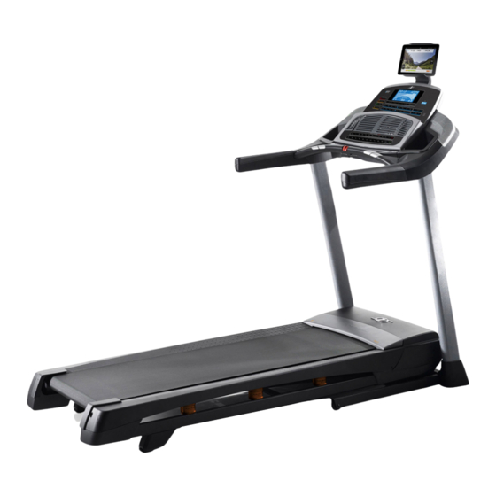
Model No. NETL12916.0
Serial No.
Write the serial number in the space
above for reference.
Serial
Number
Decal
CUSTOMER SERVICE
UNITED KINGDOM
Call: 0330 123 1045
From Ireland: 053 92 36102
Website: www.iconsupport.eu
E-mail: csuk@iconeurope.com
Write:
ICON Health & Fitness, Ltd.
Unit 1D, The Gateway
Fryers Way, Silkwood Park
OSSETT
WF5 9TJ
UNITED KINGDOM
AUSTRALIA
Call: 1800 993 770
E-mail: australiacc@iconfitness.com
Write:
ICON Health & Fitness
PO Box 635
WINSTON HILLS NSW 2153
AUSTRALIA
CAUTION
Read all precautions and instruc-
tions in this manual before using
this equipment. Save this manual
for future reference.
USER'S MANUAL
www.iconeurope.com
Advertisement
Table of Contents

Related Manuals for NordicTrack T10.0


Summary of Contents for NordicTrack T10.0
- Page 1 Model No. NETL12916.0 Serial No. USER'S MANUAL Write the serial number in the space above for reference. Serial Number Decal CUSTOMER SERVICE UNITED KINGDOM Call: 0330 123 1045 From Ireland: 053 92 36102 Website: www.iconsupport.eu E-mail: csuk@iconeurope.com Write: ICON Health & Fitness, Ltd. Unit 1D, The Gateway Fryers Way, Silkwood Park OSSETT...
-
Page 2: Table Of Contents
Bluetooth SIG, Inc. and are used under license. IOS is a trademark or registered trademark of Cisco in the U.S. and other countries and is used under license. NORDICTRACK is a registered trademark of ICON Health & Fitness, Inc. -
Page 3: Important Precautions
IMPORTANT PRECAUTIONS WARNING: To reduce the risk of burns, fire, electric shock, or injury to persons, read all important precautions and instructions in this manual and all warnings on your treadmill before using your treadmill. ICON assumes no responsibility for personal injury or property damage sus- tained by or through the use of this product. - Page 4 21. The treadmill is capable of high speeds. 26. Do not change the incline of the treadmill by Adjust the speed in small increments to placing objects under the treadmill. avoid sudden jumps in speed. 27. Never insert any object into any opening on 22.
-
Page 5: Before You Begin
BEFORE YOU BEGIN Thank you for selecting the new NORDICTRACK manual. To help us assist you, note the product model ® T 10.0 treadmill. The T 10.0 treadmill provides an number and serial number before contacting us. The impressive selection of features designed to make your model number and the location of the serial number workouts at home more effective and enjoyable. -
Page 6: Part Identification Chart
PART IDENTIFICATION CHART Use the drawings below to identify small parts used for assembly. The number in parentheses below each draw- ing is the key number of the part, from the PART LIST near the end of this manual. The number following the key number is the quantity used for assembly. -
Page 7: Assembly
ASSEMBLY • Assembly requires two persons. • To identify small parts, see page 6. • Place all parts in a cleared area and remove the • Assembly requires the following tools: packing materials. Do not dispose of the packing the included hex keys materials until you finish all assembly steps. - Page 8 2. Make sure that the power cord is unplugged. Remove the tie securing the Upright Wire (81) to the front of the Base (94). Next, identify the Right Upright (90). Have a sec- ond person hold the Right Upright near the Base (94).
- Page 9 4. Hold the Right Upright (90) against the Base (94). Make sure not to pinch the Upright Wire (81). Attach the Right Upright (90) and a Wheel (25) with two 3/8" x 2 3/8" Screws (7), a 3/8" x 1 1/4" Screw (63), a 3/8"...
- Page 10 6. Attach a Handrail (86) to the Right Upright (90) with two 5/16" x 2 1/2" Screws (28) and two 5/16" Star Washers (11); do not fully tighten the Screws yet. Make sure not to pinch the Upright Wire (81), and make sure that the wire is on the indicated side of the Upright.
- Page 11 8. Set the console assembly (F) face down on a soft surface to avoid scratching the console assembly. Remove and save the four 1/4" x 1/2" Screws (12). 9. Hold the console assembly (F) near the Pulse Crossbar (93). See the inset drawing. Connect the pulse wires (G, H).
- Page 12 10. Insert the Upright Wire (81) through one looped tie (I) and insert the console wire (J) through the other tie on the console assembly (F). See the inset drawing. Connect the Upright Wire (81) to the console wire (J). The connec- tors should slide together easily and snap into place.
- Page 13 13. Identify the Right Handrail Cover (85). Set the Right Handrail Cover on the right Handrail (86). Start two #8 x 3/4" Truss Head Screws (14) into the bottom of the Right Handrail Cover; do not fully tighten the Truss Head Screws. Next, slide the Right Handrail Cover (85) for- ward until it rests against the console assembly (F).
- Page 14 15. Remove the 5/16" Nut (34) and the 5/16" x 1 3/4" Bolt (6) from the bracket on the Base (94). Next, orient the Storage Latch (53) as shown. Attach the lower end of the Storage Latch (53) to the bracket on the Base (94) with the 5/16" x 1 3/4"...
- Page 15 17. Firmly tighten the four 3/8" x 2 3/8" Screws (7) and the two 3/8" x 1 1/4" Screws (63). Next, tighten the two 3/8" x 1 3/4" Screws (62); the Wheels (25) must turn freely. Set the Left Inner Base Cover (99) onto the lower end of the Left Upright (89).
-
Page 16: How To Use The Treadmill
HOW TO USE THE TREADMILL HOW TO PLUG IN THE POWER CORD Follow the steps below to plug in the power cord. This product must be earthed. If it should malfunc- 1. Plug the indicated end of the power cord into the tion or break down, earthing provides a path of least socket on the treadmill. - Page 17 CONSOLE DIAGRAM FEATURES OF THE CONSOLE To turn on the power, see page 18. To use the man- ual mode, see page 18. To use an onboard workout, The treadmill console offers a selection of features see page 20. To use a custom-focus weight loss workout, see page 21.
- Page 18 HOW TO TURN ON THE POWER HOW TO USE THE MANUAL MODE IMPORTANT: If the treadmill has been exposed to 1. Insert the key into the console. cold temperatures, allow it to warm to room tem- perature before you turn on the power. If you do See HOW TO TURN ON THE POWER at the left.
- Page 19 6. Follow your progress with the displays. As you exercise, the workout intensity level bar will indicate the approximate intensity level of your As you walk or run on the treadmill, the display can exercise. Press the Burn Rate increase or decrease show the following workout information: buttons to adjust the intensity level.
- Page 20 To measure your heart rate, stand on the foot HOW TO USE AN ONBOARD WORKOUT rails and hold the pulse bar with your palms on the metal contacts; avoid moving your hands. 1. Insert the key into the console. When your pulse is detected, your heart rate will be shown.
- Page 21 5. Follow your progress with the displays. HOW TO USE A CUSTOM-FOCUS WEIGHT LOSS WORKOUT See step 6 on page 19. If you select an onboard 1. Insert the key into the console. workout, the display will show the time remaining instead of the elapsed time.
- Page 22 HOW TO CONNECT YOUR SMART DEVICE TO THE THE OPTIONAL CHEST HEART RATE MONITOR CONSOLE Whether your The console supports BLUETOOTH connections to goal is to smart devices via the iFit app and to compatible heart burn fat or to rate monitors.
- Page 23 THE SETTINGS MODE HOW TO USE THE SOUND SYSTEM The console features a settings mode that keeps track To play music or audio books through the console of treadmill information and allows you to personalize sound system while you exercise, plug a 3.5 mm male console settings.
- Page 24 HOW TO ADJUST THE CUSHIONING SYSTEM HOW TO USE THE TABLET HOLDER The treadmill features a cushioning system that IMPORTANT: The tablet holder is designed for use with most full-size tablets. Do not place any other reduces the impact as you walk or run on the treadmill. electronic device or object in the tablet holder.
-
Page 25: How To Fold And Move The Treadmill
HOW TO FOLD AND MOVE THE TREADMILL HOW TO FOLD THE TREADMILL HOW TO MOVE THE TREADMILL To avoid damaging the treadmill, adjust the incline Before moving the treadmill, fold it as described at the to zero before you fold the treadmill. Then, remove left. -
Page 26: Maintenance And Troubleshooting
MAINTENANCE AND TROUBLESHOOTING MAINTENANCE c. Check the power switch located on the treadmill frame near the power cord. If the switch protrudes Regular maintenance is important for optimal per- as shown, the switch has tripped. To reset the formance and to reduce wear. Inspect and properly power switch, wait for five minutes and then press tighten all parts each time the treadmill is used. - Page 27 SYMPTOM: The displays of the console do not SYMPTOM: The walking belt slows when walked on function properly a. If an extension cord is needed, use only a 3-conduc- a. Remove the key from the console and UNPLUG tor, 14-gauge (1 mm ) cord that is no longer than 5 THE POWER CORD.
- Page 28 SYMPTOM: The walking belt is not centered SYMPTOM: The walking belt slips when walked on between the foot rails. IMPORTANT: If the walking belt rubs against the foot rails, the walking belt a. First, remove the key and UNPLUG THE POWER may become damaged.
-
Page 29: Exercise Guidelines
EXERCISE GUIDELINES Burning Fat—To burn fat effectively, you must exer- WARNING: cise at a low intensity level for a sustained period of Before beginning this time. During the first few minutes of exercise, your or any exercise program, consult your physi- body uses carbohydrate calories for energy. -
Page 30: Part List
PART LIST Model No. NETL12916.0 R0516B Key No. Qty. Description Key No. Qty. Description #8 x 1/2" Screw 9/32" Plastic Bushing #8 x 3/4" Screw 3/8" Plastic Bushing 5/16" x 2 1/4" Bolt Storage Latch 5/16" x 3/4" Screw Drive Motor #10 Star Washer Motor Belt 5/16"... - Page 31 Key No. Qty. Description Key No. Qty. Description 3/8" Washer Motor Isolator Magnet Left Speaker Grill Reed Switch Clip Right Speaker Grill Reed Switch Speaker #8 Nut Left Speaker Cover #8 x 1/2" Machine Screw Right Speaker Cover Filter Motor Bushing 3/16"...
-
Page 32: Exploded Drawing
EXPLODED DRAWING A Model No. NETL12916.0 R0516B... - Page 33 EXPLODED DRAWING B Model No. NETL12916.0 R0516B...
- Page 34 EXPLODED DRAWING C Model No. NETL12916.0 R0516B...
- Page 35 EXPLODED DRAWING D Model No. NETL12916.0 R0516B...
-
Page 36: Ordering Replacement Parts
ORDERING REPLACEMENT PARTS To order replacement parts, please see the front cover of this manual. To help us assist you, be prepared to provide the following information when contacting us: • the model number and serial number of the product (see the front cover of this manual) •...
Need help?
Do you have a question about the T10.0 and is the answer not in the manual?
Questions and answers