
Related Manuals for Yamaha XCITY VP250


Summary of Contents for Yamaha XCITY VP250
- Page 1 Read this manual carefully before operating this vehicle. OWNER’S MANUAL VP250 5B2-F8199-E1...
- Page 3 EAU10113 Welcome to the Yamaha world of motorcycling! As the owner of the VP250, you are benefiting from Yamaha’s vast experience and newest technology regarding the design and manufacture of high-quality products, which have earned Yamaha a reputation for dependability.
- Page 4 IMPORTANT MANUAL INFORMATION EAU10132 Particularly important information is distinguished in this manual by the following notations: This is the safety alert symbol. It is used to alert you to potential personal injury hazards. Obey all safety messages that follow this symbol to avoid possible injury or death.
- Page 5 IMPORTANT MANUAL INFORMATION EAUM1010 VP250 OWNER’S MANUAL ©2008 by MBK INDUSTRIE 1st edition, July 2008 All rights reserved Any reprinting or unauthorized use without the written permission of MBK INDUSTRIE is expressly prohibited. Printed in France.
-
Page 6: Table Of Contents
TABLE OF CONTENTS SAFETY INFORMATION ....1-1 FOR YOUR SAFETY – Cast wheels ......... 6-16 Further safe-riding points ....1-5 PRE-OPERATION CHECKS ..... 4-1 Front and rear brake lever free play ........... 6-16 DESCRIPTION ........2-1 OPERATION AND IMPORTANT Checking the front and rear brake Left view ..........2-1 RIDING POINTS......... - Page 7 TABLE OF CONTENTS SCOOTER CARE AND STORAGE ...7-1 Care ..........7-1 Storage ...........7-3 SPECIFICATIONS ......8-1 CONSUMER INFORMATION.....9-1 Identification numbers ....9-1...
-
Page 8: Safety Information
SAFETY INFORMATION EAU10263 Safe Riding • Ride where other motorists can Perform the pre-operation checks each see you. Avoid riding in another time you use the vehicle to make sure it motorist’s blind spot. Be a Responsible Owner is in safe operating condition. Failure to Many accidents involve inexperi- As the vehicle’s owner, you are respon- inspect or maintain the vehicle properly... - Page 9 SAFETY INFORMATION cessive speed or undercornering This scooter is designed for on- A passenger should also observe (insufficient lean angle for the road use only. It is not suitable for the above precautions. speed). off-road use. • Always obey the speed limit and Avoid Carbon Monoxide Poisoning never travel faster than warrant- Protective apparel...
- Page 10 Yamaha accessories, which are avail- the scooter is changed. To avoid the imize imbalance or instability. able only from a Yamaha dealer, have possibility of an accident, use extreme Shifting weights can create a sud- been designed, tested, and approved caution when adding cargo or accesso- den imbalance.
-
Page 11: Specifications
• Accessories fitted to the handle- Use caution when adding electri- genuine Yamaha accessories, recog- bar or the front fork area can cal accessories. If electrical acces- nize that some aftermarket accessories... -
Page 12: Further Safe-Riding Points
SAFETY INFORMATION EAU10372 Always wear a helmet, gloves, Further safe-riding points trousers (tapered around the cuff Be sure to signal clearly when and ankle so they do not flap), and making turns. a bright colored jacket. Braking can be extremely difficult Do not carry too much luggage on on a wet road. -
Page 13: Description
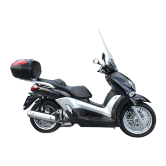
DESCRIPTION EAU32220 Left view Without rear carrier 1. Rear storage compartment (page 3-11) 8. Front brake pads (page 6-17) 2. Shock absorber assembly spring preload adjusting ring (page 3-13) 3. Final transmission oil filler cap (page 6-10) 4. Air filter element (page 6-12) 5. - Page 14 DESCRIPTION With rear carrier 1. Rear storage compartment (page 3-11) 2. Shock absorber assembly spring preload adjusting ring (page 3-13) 3. Final transmission oil filler cap (page 6-10) 4. Air filter element (page 6-12) 5. V-belt case air filter element (page 6-12) 6.
-
Page 15: Right View
DESCRIPTION EAU32230 Right view Without rear carrier 1. Grab bar (page 5-2) 8. Rear brake pads (page 6-17) 2. Main fuse/fuse box (page 6-23) 3. Battery (page 6-22) 4. Coolant reservoir cap (page 6-11) 5. Fuel tank cap (page 3-7) 6. - Page 16 DESCRIPTION With rear carrier 1. Grab bar (page 5-2) 2. Main fuse/fuse box (page 6-23) 3. Battery (page 6-22) 4. Coolant reservoir cap (page 6-11) 5. Fuel tank cap (page 3-7) 6. Engine oil filler cap (page 6-8) 7. Centerstand (page 6-20) 8.
-
Page 17: Controls And Instruments
DESCRIPTION EAU10430 Controls and instruments 7 8 9 PUSH 1. Rear brake lever (page 3-7) 9. Front brake lever (page 3-7) 2. Left handlebar switches (page 3-6) 3. Front storage compartment (page 3-11) 4. Speedometer/Multi-function display (page 3-2/page 3-3) 5. Luggage hook (page 3-14) 6. -
Page 18: Instrument And Control Functions
INSTRUMENT AND CONTROL FUNCTIONS EAU10460 EAU10661 EAU11003 Main switch/steering lock OFF “ ” Indicator and warning lights All electrical systems are off. The key can be removed. EWA10061 WARNING PUSH Never turn the key to “ ” or “ ” while the vehicle is moving. -
Page 19: Speedometer
This warning light comes on if a prob- lem is detected in the electrical circuit monitoring the engine. If this occurs, have a Yamaha dealer check the self- diagnosis system. The electrical circuit of the warning light can be checked by turning the key to “... -
Page 20: Coolant Temperature Gauge
INSTRUMENT AND CONTROL FUNCTIONS EAU12172 EAUM2480 two tripmeters (which show the Coolant temperature gauge Multi-function display distance traveled since they were last set to zero, the time passed since the tripmeters were set to ze- ro, and the average speed traveled during this time) a fuel reserve tripmeter (which shows the distance traveled since... - Page 21 INSTRUMENT AND CONTROL FUNCTIONS Trip/Fuel → Trip 1 → Trip 2 → Total → Odometer and tripmeter modes Pushing the “SET” button when in the Pushing the “MODE” button switches tripmeter mode switches the display Trip/fuel the display between the odometer between the different tripmeter func- mode “Total”...
- Page 22 INSTRUMENT AND CONTROL FUNCTIONS Ambient temperature display Oil change indicator “OIL” ZAUM0394 ZAUM0396 ZAUM0582 3. Push the “MODE” button, and the 1. Frost warning indicator “ ” 1. Oil change indicator “OIL” minute digits will start flashing. 2. Minus item 4.
-
Page 23: Handlebar Switches
INSTRUMENT AND CONTROL FUNCTIONS EAU12347 EAUS1020 Handlebar switches Dimmer switch “ ” The oil change indicator will come Set this switch to “ ” for the high Left on at the initial 1000 km (600 mi) beam and to “ ”... -
Page 24: Front Brake Lever
INSTRUMENT AND CONTROL FUNCTIONS EAU12900 EAU12950 EAUM2161 Front brake lever Rear brake lever Fuel tank cap To open the fuel tank cap ZAUM0084 ZAUM0085 1. Front brake lever 1. Rear brake lever ZAUM0643 The front brake lever is located on the The rear brake lever is located on the 1. -
Page 25: Fuel
INSTRUMENT AND CONTROL FUNCTIONS EWA11091 EAU13212 Fuel WARNING Make sure there is sufficient gasoline in Make sure that the fuel tank cap is the tank. properly closed after filling fuel. EWA10881 Leaking fuel is a fire hazard. WARNING Gasoline and gasoline vapors are extremely flammable. -
Page 26: Catalytic Converters
Your Yamaha engine has been de- signed to use premium unleaded gaso- line with a research octane number of 95 or higher. If knocking (or pinging) oc-... -
Page 27: Seat
INSTRUMENT AND CONTROL FUNCTIONS ECA10701 EAU13932 2. Remove the key from the main Seat NOTICE switch if the scooter will be left un- attended. Use only unleaded gasoline. The use To open the seat of leaded gasoline will cause unre- 1. -
Page 28: Storage Compartments
INSTRUMENT AND CONTROL FUNCTIONS EAUM2510 To lock the storage compartment EWAT1051 Storage compartments WARNING Insert the key in the lock and turn it 1/4 turn counterclockwise, and then re- Do not exceed the load limit of 5 Front storage compartment move the key. -
Page 29: Windshield
INSTRUMENT AND CONTROL FUNCTIONS Do not keep anything valuable EAUM2490 EWA10920 Windshield WARNING or breakable in the storage com- To suit the rider’s preference, the wind- partment. After adjusting the windshield: shield height can be changed to one of Securely tighten the windshield To store a helmet in the storage com- four positions. -
Page 30: Adjusting The Shock Absorber Assemblies
INSTRUMENT AND CONTROL FUNCTIONS EAU14881 EWA10210 EAU15112 Adjusting the shock absorber Carrier (if applicable) WARNING assemblies EWA10171 Always adjust both shock absorber WARNING assemblies equally, otherwise poor Do not exceed the load limit of 5 handling and loss of stability may kg (11 lb) for the carrier. -
Page 31: Luggage Hook
Therefore, check this system regularly as described below and have a Yamaha dealer re- ZAUM0648 pair it if it does not function proper- 1. Sidestand switch The sidestand is located on the left side of the frame. -
Page 32: Ignition Circuit Cut-Off System
INSTRUMENT AND CONTROL FUNCTIONS EAU45051 Ignition circuit cut-off system The ignition circuit cut-off system (com- prising the sidestand switch and brake light switches) has the following func- tions. It prevents starting when the side- stand is up, but neither brake is ap- plied. - Page 33 WARNING With the engine turned off: 1. Move the sidestand down. If a malfunction is noted, have a Yamaha 2. Make sure that the engine stop switch is turned on. dealer check the system before riding. 3. Turn the key on.
-
Page 34: For Your Safety - Pre-Operation Checks
• If necessary, add recommended coolant to specified level. 6-11 • Check cooling system for leakage. • Check operation. • If soft or spongy, have Yamaha dealer bleed hydraulic system. • Check brake pads for wear. Front brake • Replace if necessary. - Page 35 • Make sure that operation is smooth. • Check cable free play. Throttle grip 6-13, 6-19 • If necessary, have Yamaha dealer adjust cable free play and lubricate cable and grip housing. • Check for damage. • Check tire condition and tread depth.
-
Page 36: Operation And Important Riding Points
See page 5-4 for engine break-in in- gle sensor to stop the engine in case of understand, ask your Yamaha dealer. structions prior to operating the ve- a turnover. To start the engine after a EWA10271 hicle for the first time. -
Page 37: Starting Off
OPERATION AND IMPORTANT RIDING POINTS EAU16761 EAU16780 Starting off Acceleration and deceleration Before starting off, allow the engine to warm up. 1. While pulling the rear brake lever with your left hand and holding the grab bar with your right hand, push ZAUM0649 the scooter off the centerstand. -
Page 38: Braking
OPERATION AND IMPORTANT RIDING POINTS EAU16793 EAU16820 Braking Tips for reducing fuel con- EWA10300 sumption WARNING Fuel consumption depends largely on Avoid braking hard or suddenly your riding style. Consider the following (especially when leaning over to tips to reduce fuel consumption: one side), otherwise the scooter Avoid high engine speeds during may skid or overturn. -
Page 39: Engine Break-In
Since the engine is brand new, do not Since the engine and exhaust immediately have a Yamaha dealer put an excessive load on it for the first system can become very hot, check the vehicle. -
Page 40: Periodic Maintenance And Adjustment
If you do not have the tools or experi- weather, terrain, geographical location, formation about carbon monox- ence required for a particular job, have and individual use, the maintenance in- ide. a Yamaha dealer perform it for you. tervals may need to be shortened. EWA10330 EWA10321 WARNING WARNING... -
Page 41: Periodic Maintenance And Lubrication Chart
From 50000 km (30000 mi), repeat the maintenance intervals starting from 10000 km (6000 mi). Items marked with an asterisk should be performed by a Yamaha dealer as they require special tools, data and technical skills. - Page 42 PERIODIC MAINTENANCE AND ADJUSTMENT ODOMETER READING ANNUAL ITEM CHECK OR MAINTENANCE JOB 1000 km 10000 km 20000 km 30000 km 40000 km CHECK (600 mi) (6000 mi) (12000 mi) (18000 mi) (24000 mi) √ √ √ √ √ • Check for cracks or damage. 8 * Brake hoses •...
- Page 43 PERIODIC MAINTENANCE AND ADJUSTMENT ODOMETER READING ANNUAL ITEM CHECK OR MAINTENANCE JOB 1000 km 10000 km 20000 km 30000 km 40000 km CHECK (600 mi) (6000 mi) (12000 mi) (18000 mi) (24000 mi) Shock absorber as- • Check operation and shock ab- √...
- Page 44 PERIODIC MAINTENANCE AND ADJUSTMENT EAU18670 The air filter needs more frequent service if you are riding in unusually wet or dusty areas. Hydraulic brake service • Regularly check and, if necessary, correct the brake fluid level. • Every two years replace the internal components of the brake master cylinders and calipers, and change the brake fluid.
-
Page 45: Removing And Installing Cowlings And Panels
PERIODIC MAINTENANCE AND ADJUSTMENT EAU18712 Removing and installing cowl- ings and panels The cowlings and panels shown need to be removed to perform some of the maintenance jobs described in this chapter. Refer to this section each time a cowling or panel needs to be re- moved and installed. -
Page 46: Checking The Spark Plug
Do not attempt to diagnose Place the panel in the original position, such problems yourself. Instead, have and then install the screws. a Yamaha dealer check the vehicle. If the spark plug shows signs of elec- trode erosion and excessive carbon or ZAUM0656 other deposits, it should be replaced. -
Page 47: Engine Oil
PERIODIC MAINTENANCE AND ADJUSTMENT Before installing a spark plug, the spark EAUM1551 Engine oil plug gap should be measured with a If a torque wrench is not available when The engine oil level should be checked wire thickness gauge and, if necessary, installing a spark plug, a good estimate before each ride. - Page 48 PERIODIC MAINTENANCE AND ADJUSTMENT 3. Remove the engine oil filler cap 5. Install the washer and the engine and the engine oil drain bolt to oil drain bolt, and then tighten the drain the oil from the crankcase. drain bolt to the specified torque. Tightening torque: Engine oil drain bolt: 20 Nm (2.0 m·kgf, 14 ft·lbf)
-
Page 49: Final Transmission Oil
If any leakage is found, have a it for oil leakage. If oil is leaking, im- Yamaha dealer check and repair the mediately turn the engine off and scooter. In addition, the final transmis- check for the cause. -
Page 50: Coolant
PERIODIC MAINTENANCE AND ADJUSTMENT 6. Refill with the specified amount of EAU20070 Coolant the recommended final transmis- The coolant level should be checked sion oil, and then install and tighten before each ride. In addition, the cool- the oil filler cap. WARNING! Make ant must be changed at the intervals sure that no foreign material en- specified in the periodic maintenance... -
Page 51: Air Filter And V-Belt Case Air Filter Elements
Have a placed and the V-belt case air filter ele- Yamaha dealer check the anti- Yamaha dealer change the coolant. ment should be cleaned at the intervals freeze content of the coolant as... -
Page 52: Checking The Throttle Cable Free Play
NOTICE: Make sure that each fil- sary, have a Yamaha dealer adjust it. ter element is properly seated in its case. The engine should nev- 1. V-belt case air filter cover er be operated without the filter 2. -
Page 53: Valve Clearance
The tire air pressure must be ad- must be adjusted by a Yamaha dealer justed in accordance with the at the intervals specified in the periodic Tire air pressure riding speed and with the total maintenance and lubrication chart. - Page 54 This model is equipped with tubeless edge and experience. tires. After extensive tests, only the tires list- ed below have been approved for this model by Yamaha Motor Co., Ltd. Front tire: Size: 120/70-16 M/C 57P Manufacturer/model: ZAUM0054 PIRELLI/SPORT DEMON FRONT 1.
-
Page 55: Cast Wheels
The wheel rims should be checked Yamaha dealer bleed the system be- for cracks, bends or warpage be- fore operating the vehicle. Air in the fore each ride. If any damage is... -
Page 56: Checking The Front And Rear Brake Pads
EAU22580 Checking the front and rear Checking the brake fluid level peared, have a Yamaha dealer replace brake pads the brake pads as a set. Front brake The front and rear brake pads must be... -
Page 57: Changing The Brake Fluid
Changing the brake fluid is above the minimum level mark and ter the brake fluid reservoir when Have a Yamaha dealer change the replenish if necessary. A low brake fluid refilling. Water will significantly brake fluid at the intervals specified in... -
Page 58: Checking And Lubricating The Cables
If a cable is damaged maintenance chart. or does not move smoothly, have a Yamaha dealer check or replace it. WARNING! Damage to the outer sheath may interfere with proper ca- ZAUM0061... -
Page 59: Checking And Lubricating The Centerstand And Sidestand
If the centerstand or sidestand does Check the inner tubes for scratches, not move up and down smoothly, damage and excessive oil leakage. have a Yamaha dealer check or re- pair it. Otherwise, the centerstand or To check the operation sidestand could contact the ground ZAUM0667 1. -
Page 60: Checking The Steering
2. Hold the lower ends of the front fork does not operate smoothly, fork legs and try to move them for- have a Yamaha dealer check or re- ward and backward. If any free pair it. play can be felt, have a Yamaha dealer check or repair the steering. -
Page 61: Battery
To charge the battery 2. If the battery will be stored for more Electrolyte is poisonous and Have a Yamaha dealer charge the bat- than two months, check it at least dangerous since it contains sul- tery as soon as possible if it seems to... -
Page 62: Replacing The Fuses
PERIODIC MAINTENANCE AND ADJUSTMENT 3. Fully charge the battery before in- EAU23526 Replacing the fuses 4 5 6 7 stallation. ECA16530 NOTICE Always keep the battery charged. 9 10 Storing a discharged battery can cause permanent battery damage. ZAUM0673 1. Fuse box ZAUM0672 2. -
Page 63: Replacing A Headlight Bulb
4. If the fuse immediately blows using a cloth moistened with al- again, have a Yamaha dealer cohol or thinner. check the electrical system. Headlight lens Do not affix any type of tinted film or stickers to the headlight lens. - Page 64 6. Connect the headlight coupler. 7. Install the headlight bulb cover. 8. Install the cowling. 9. Have a Yamaha dealer adjust the headlight beam if necessary. ZAUM0677 1. Headlight bulb cover 3. Disconnect the headlight coupler.
-
Page 65: Replacing A Front Turn Signal Light Bulb
6. Install the socket (together with the NOTICE bulb) by turning it clockwise. 1. Place the vehicle on the center- It is advisable to have a Yamaha 7. Install the cowling. stand. dealer perform this job. 2. Remove panel B. (See page 6-6.) 3. -
Page 66: Replacing The License Plate Light Bulb
PERIODIC MAINTENANCE AND ADJUSTMENT EAUM2201 EAUM2212 Replacing the license plate Replacing an auxiliary light light bulb bulb 1. Remove the socket (together with This model is equipped with two auxil- the bulb) by pulling it out. iary lights. If an auxiliary light bulb burns out, replace it as follows. -
Page 67: Troubleshooting
However, should your scooter re- quire any repair, take it to a Yamaha dealer, whose skilled technicians have the necessary tools, experience, and know-how to service the scooter prop- erly. -
Page 68: Troubleshooting Charts
Remove the spark plug and check the electrodes. The engine does not start. Have a Yamaha dealer check the vehicle. Check the battery. 4. Battery The engine turns over The battery is good. - Page 69 Start the engine. If the engine overheats again, have a The coolant level Yamaha dealer check and repair the cooling system. is OK. If coolant is not available, tap water can be temporarily used instead, provided that it is changed to the recommended coolant as soon as possible.
-
Page 70: Scooter Care And Storage
SCOOTER CARE AND STORAGE EAU26093 ucts onto seals, gaskets and wheel off any detergent residue using Care axles. Always rinse the dirt and de- plenty of water, as it is harmful While the open design of a scooter re- greaser off with water. to plastic parts. - Page 71 SCOOTER CARE AND STORAGE Test the product on a small hid- 3. To prevent corrosion, it is recom- den part of the windshield to mended to apply a corrosion pro- Salt sprayed on roads in the winter may make sure that it does not leave tection spray metal,...
-
Page 72: Storage
Turn the engine over several To prevent corrosion, avoid Consult a Yamaha dealer for ad- times with the starter. (This will damp cellars, stables (because vice on what products to use. - Page 73 SCOOTER CARE AND STORAGE 5. Check and, if necessary, correct the tire air pressure, and then lift the scooter so that both of its wheels are off the ground. Alterna- tively, turn the wheels a little every month in order to prevent the tires from becoming degraded in one spot.
-
Page 74: Specifications
SPECIFICATIONS Dimensions: Engine oil: Air filter: Overall length: Type: Air filter element: 2175 mm (85.6 in) (without rear carrier) SAE 10W-30, SAE 10W-40, SAE 15W-40, Oil-coated paper element 2215 mm (87.2 in) (with rear carrier) SAE 20W-40 or SAE 20W-50 Fuel: Overall width: Recommended fuel:... - Page 75 SPECIFICATIONS Transmission type: Front: Front suspension: V-belt automatic 170 kPa (1.70 kgf/cm², 25 psi) Type: Operation: Rear: Telescopic fork Centrifugal automatic type 190 kPa (1.90 kgf/cm², 28 psi) Spring/shock absorber type: Chassis: Loading condition: Coil spring/oil damper 90–185 kg (198–408 lb) Frame type: Wheel travel: Front:...
- Page 76 SPECIFICATIONS Front turn signal light: Backup fuse: 12 V, 10.0 W × 2 5.0 A Rear turn signal light: 12 V, 10.0 W × 2 Auxiliary light: 12 V, 5.0 W × 2 License plate light: 12 V, 5.0 W × 1 Meter lighting: High beam indicator light: Turn signal indicator light:...
-
Page 77: Consumer Information
Record the key identification number, vehicle identification number and mod- el label information in the spaces pro- vided below for assistance when ordering spare parts from a Yamaha dealer or for reference in case the vehi- cle is stolen. KEY IDENTIFICATION NUMBER:... - Page 78 1. Model label The model label is affixed to the bottom of the seat. (See page 3-10.) Record the information on this label in the space provided. This information will be needed when ordering spare parts from a Yamaha dealer.
- Page 79 INDEX Front and rear brake pads, checking ..6-17 Shock absorber assemblies, Front fork, checking.......6-20 adjusting ..........3-13 Acceleration and deceleration ....5-2 Fuel ............3-8 Sidestand..........3-14 Air filter and V-belt case air filter Fuel consumption, tips for reducing ..5-3 Spark plug, checking ......6-7 elements..........
- Page 80 YAMAHA MOTOR CO., LTD. PRINTED IN FRANCE 2008.07 (E)
Need help?
Do you have a question about the XCITY VP250 and is the answer not in the manual?
Questions and answers