Table of Contents
Advertisement
Advertisement
Table of Contents
Troubleshooting

Related Manuals for Yamaha MAJESTY 400


Summary of Contents for Yamaha MAJESTY 400
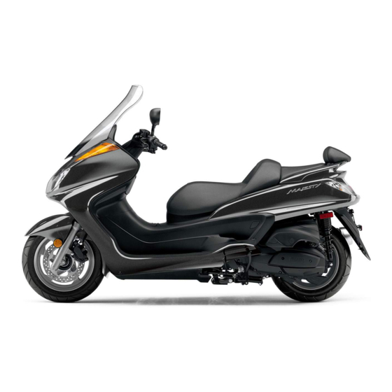
- Page 1 OWNER’S MANUAL YP400 YP400A 5RU-28199-E4...
- Page 2 EAU26944 DECLARATION of CONFORMITY Company: YAMAHA MOTOR ELECTRONICS CO., LTD. Address: 1450-6, Mori, Mori-Machi, Shuchi-gun, Shizuoka-Ken, 437-0292 Japan Hereby declare that the product: Kind of equipment: IMMOBILIZER Type-designation: 5SL-00 is in compliance with following norm(s) or documents: R&TTE Directive(1999/5/EC) EN300 330-2 v1.1.1(2001-6), EN60950-1(2001)
- Page 3 EAU10110 Welcome to the Yamaha world of motorcycling! As the owner of the YP400/YP400A, you are benefiting from Yamaha’s vast experience and newest technology regarding the design and manufacture of high-quality products, which have earned Yamaha a reputation for dependability.
- Page 4 This manual should be considered a permanent part of this scooter and should remain with it even if the scooter is sub- sequently sold. Yamaha continually seeks advancements in product design and quality. Therefore, while this manual contains the most current product information available at the time of printing, there may be minor discrepancies between your scooter and this manual.
- Page 5 IMPORTANT MANUAL INFORMATION EAU10200 YP400/YP400A OWNER’S MANUAL ©2007 by Yamaha Motor Co., Ltd. 1st edition, August 2007 All rights reserved. Any reprinting or unauthorized use without the written permission of Yamaha Motor Co., Ltd. is expressly prohibited. Printed in Japan.
-
Page 6: Table Of Contents
TABLE OF CONTENTS SAFETY INFORMATION ....1-1 Ignition circuit cut-off system ..3-20 Valve clearance ......6-22 Further safe-riding points ....1-4 Tires ..........6-22 PRE-OPERATION CHECKS ....4-1 Cast wheels ........6-24 DESCRIPTION ........2-1 Pre-operation check list ....4-2 Front and rear brake lever free Left view ...........2-1 play .......... - Page 7 TABLE OF CONTENTS Replacing the license plate light bulb ..........6-38 Replacing an auxiliary light bulb ..6-38 Troubleshooting ......6-39 Troubleshooting charts ....6-40 SCOOTER CARE AND STORAGE ...........7-1 Matte color caution ......7-1 Care ..........7-1 Storage ..........7-3 SPECIFICATIONS ......8-1 CONSUMER INFORMATION....9-1 Identification numbers .....9-1...
-
Page 8: Safety Information
SAFETY INFORMATION EAU10261 TIONS. Many accidents involve inexperi- enced operators. In fact, many op- SCOOTERS ARE SINGLE TRACK Safe riding erators who have been involved in VEHICLES. THEIR SAFE USE AND Always make pre-operation accidents do not even have a cur- OPERATION DEPENDENT checks. - Page 9 SAFETY INFORMATION Always signal before turning or ries. The use of a safety helmet is the approved by Yamaha, or the removal of changing lanes. Make sure that single most critical factor in the preven- original equipment, may render the other motorists can see you.
- Page 10 Gasoline and exhaust gas this scooter. Since Yamaha cannot test should be kept to a minimum. GASOLINE IS HIGHLY FLAMMA- all other accessories that may be avail-...
-
Page 11: Further Safe-Riding Points
SAFETY INFORMATION Take care not to spill any gaso- sene heater, or near an open EAU10371 Further safe-riding points line on the engine or exhaust flame), otherwise it could catch Be sure to signal clearly when system when refueling. fire. making turns. - Page 12 SAFETY INFORMATION and ankle so they do not flap), and a bright colored jacket. Do not carry too much luggage on the scooter. An overloaded scoot- er is unstable.
- Page 13 SAFETY INFORMATION...
-
Page 14: Description
DESCRIPTION EAU10410 Left view 1. Headlight (page 6-35) 9. Air filter element (left) (page 6-19) 2. Fuel tank cap (page 3-13) 10. Engine oil filter element (page 6-13) 3. Rear storage compartment (page 3-17) 11. Sidestand (page 3-19, 6-29) 4. V-belt case air filter element (page 6-19) 5. -
Page 15: Right View
DESCRIPTION EAU10420 Right view 1. Grab bar (page 5-2) 2. Passenger seat (page 3-15) 3. Rider seat (page 3-15) 4. Coolant reservoir (page 6-17) 5. Radiator 6. Centerstand (page 6-29) 7. Air filter element (right) (page 6-19) 8. Shock absorber assembly spring preload adjusting ring (page 3-18) -
Page 16: Controls And Instruments
DESCRIPTION EAU10430 Controls and instruments 1. Rear brake lever (page 3-11) 9. Throttle grip (page 6-22) 2. Left handlebar switches (page 3-9) 10. Front storage compartment B (page 3-17) 3. Rear brake lock lever (page 3-11) 11. Main switch/steering lock (page 3-2) 4. -
Page 17: Instrument And Control Functions
Do not expose any key to exces- the vehicle along with all three keys to sively high temperatures. a Yamaha dealer to have them re-reg- Do not place any key close to istered. Do not use the key with the red magnets (this includes, but not bow for driving. -
Page 18: Main Switch/Steering Lock
INSTRUMENT AND CONTROL FUNCTIONS as they may cause signal inter- EAU10471 come on, and the engine can be start- Main switch/steering lock ference. ed. The key cannot be removed. NOTE: The headlights come on automatically when the engine is started and stay on until the key is turned to “OFF”... -
Page 19: Indicator And Warning Lights
INSTRUMENT AND CONTROL FUNCTIONS To unlock the steering wise the battery may discharge. EAU11003 Indicator and warning lights Push the key in, and then turn it to “OFF” while still pushing it. EWA10060 WARNING Never turn the key to “OFF” or “LOCK”... - Page 20 “ ” and turning the key for a few seconds, then go off, have a to “ON”. The warning light should come Yamaha dealer check the electrical cir- EAU11480 Engine trouble warning light “ ” on for a few seconds, and then go off. If cuit.
-
Page 21: Speedometer
INSTRUMENT AND CONTROL FUNCTIONS EAU11601 EAU11872 EAU34136 Speedometer Tachometer Multi-function display EWA12311 WARNING Be sure to stop the vehicle before making any setting changes to the multi-function display. 1. Speedometer 1. Tachometer 2. Tachometer red zone The speedometer shows the riding The electric tachometer allows the rider speed. - Page 22 INSTRUMENT AND CONTROL FUNCTIONS cator started flashing) tor will start flashing, and the display will a self-diagnosis device automatically change to the fuel re- a clock serve tripmeter mode “TRIP F” and an ambient temperature display start counting the distance traveled an oil change indicator from that point.
-
Page 23: V-Belt Replacement Indicator
3. If the indicator does not come on, CAUTION: in the fuel tank. The display segments have a Yamaha dealer check the Do not operate the engine if it is of the fuel meter disappear towards “E” electrical circuit. -
Page 24: Self-Diagnosis Device
Yamaha dealer check the two-digit error code when the key is any error codes, note the code number, electrical circuit. turned to “ON”. and then have a Yamaha dealer check the vehicle. NOTE: Self-diagnosis device If the multi-function display indicates er-... -
Page 25: Anti-Theft Alarm (Optional)
This display shows the ambient tem- This model can be equipped with an perature from –10 °C to 50 °C in 1 °C optional anti-theft alarm by a Yamaha Left increments. The temperature displayed dealer. Contact a Yamaha dealer for may vary from the ambient tempera- more information. - Page 26 INSTRUMENT AND CONTROL FUNCTIONS Right leased, the switch returns to the center EAU42810 position. To cancel the turn signal (for ABS models) lights, push the switch in after it has re- The engine trouble warning light and turned to the center position. ABS warning light will come on when the key is turned to “ON”...
-
Page 27: Front Brake Lever
INSTRUMENT AND CONTROL FUNCTIONS EAU12900 EAU12950 EAU12962 Front brake lever Rear brake lever Rear brake lock lever 1. Front brake lever 1. Rear brake lever 1. Rear brake lock lever The front brake lever is located on the The rear brake lever is located on the This vehicle is equipped with a rear right handlebar grip. -
Page 28: Abs (For Abs Models)
ABS (for ABS models) To provide secure locking of the When the ABS is activated, the The Yamaha ABS (Anti-lock Brake rear wheel, apply the rear brake le- brakes are operated in the usual System) features a dual electronic con- ver first before moving the rear way. -
Page 29: Fuel Tank Cap
INSTRUMENT AND CONTROL FUNCTIONS EAU13162 move it. Fuel tank cap 3. Close the lid. EWA11120 WARNING To open the fuel tank cap 1. Open the lid by sliding the lever Be sure that the fuel tank cap is forward, and then pull the lever up. properly installed and locked before riding the scooter. -
Page 30: Fuel
EWA10880 cause unrepairable damage to WARNING the catalytic converter. Your Yamaha engine has been de- Do not overfill the fuel tank, oth- Never park the vehicle near pos- signed to use regular unleaded gaso- erwise it may overflow when the... -
Page 31: Seats
INSTRUMENT AND CONTROL FUNCTIONS EAU34140 To close the rider seat Seats 1. Fold the rider seat down, and then push it down to lock it in place. 2. Remove the key from the main switch if the scooter will be left un- attended. -
Page 32: Adjusting The Rider Seat
INSTRUMENT AND CONTROL FUNCTIONS To install the passenger seat EAU34150 Adjusting the rider seat 1. Insert the projections on the pas- senger seat into the holders as shown, place the passenger seat in the original position, and then in- stall the bolt. 1. -
Page 33: Storage Compartments
INSTRUMENT AND CONTROL FUNCTIONS EAU14492 and then remove it. Storage compartments Front storage compartment A To open the storage compartment when it is locked, insert the key in the lock, turn it counterclockwise, and then grasp the lock while pushing the button To open the storage compartment when it is unlocked, simply grasp the 1. -
Page 34: Adjusting The Shock Absorber Assemblies
INSTRUMENT AND CONTROL FUNCTIONS being washed, wrap any articles EAU14890 Adjusting the shock absorber stored in the compartment in a assemblies plastic bag. Do not keep anything valuable or breakable in the storage com- partment. ECA11100 CAUTION: Do not leave the rider seat open for an extended period of time, other- 1. -
Page 35: Sidestand
Yamaha’s ignition circuit cut-off Standard: system has been designed to assist the operator in fulfilling the respon- Maximum (hard): sibility of raising the sidestand be- fore starting off. Therefore, check this system regularly as described below and have a Yamaha dealer re- 3-19... -
Page 36: Ignition Circuit Cut-Off System
It cuts the running engine when the sidestand is moved down. Periodically check the operation of the ignition circuit cut-off system according to the following procedure. EWA10250 WARNING If a malfunction is noted, have a Yamaha dealer check the system be- fore riding. 3-20... - Page 37 Does the engine start? The sidestand switch may be defective. The scooter should not be ridden until checked by a Yamaha dealer. With the engine still off: 6. Move the sidestand up. 7. Keep the front or rear brake applied.
-
Page 38: Pre-Operation Checks
PRE-OPERATION CHECKS EAU15593 The condition of a vehicle is the owner’s responsibility. Vital components can start to deteriorate quickly and unexpectedly, even if the vehicle remains unused (for example, as a result of exposure to the elements). Any damage, fluid leakage or loss of tire air pressure could have serious consequences. -
Page 39: Pre-Operation Check List
If necessary, add recommended brake fluid to specified level. Check hydraulic system for leakage. Make sure that operation is smooth. Check cable free play. Throttle grip 6-22, 6-29 If necessary, have Yamaha dealer adjust cable free play and lubricate cable and grip housing. - Page 40 Make sure that all nuts, bolts and screws are properly tightened. Chassis fasteners — Tighten if necessary. Instruments, lights, signals Check operation. — and switches Correct if necessary. Check operation of ignition circuit cut-off system. Sidestand switch 3-19 If system is defective, have Yamaha dealer check vehicle.
-
Page 41: Operation And Important Riding Points
ECA11040 Consult a Yamaha dealer re- In order for the ignition circuit cut-off CAUTION: garding any control or function system to enable starting, the side-... -
Page 42: Starting Off
OPERATION AND IMPORTANT RIDING POINTS EAU45091 EAU16780 EAU16792 Starting off Acceleration and deceleration Braking 1. While pulling the rear brake lever 1. Close the throttle completely. with your left hand and holding the 2. Apply both front and rear brakes grab bar with your right hand, push simultaneously while gradually in- the scooter off the centerstand. -
Page 43: Tips For Reducing Fuel Consumption
OPERATION AND IMPORTANT RIDING POINTS Rear ing downhill can be very diffi- EAU16820 Tips for reducing fuel cult. consumption Fuel consumption depends largely on your riding style. Consider the following tips to reduce fuel consumption: Avoid high engine speeds during acceleration. -
Page 44: Engine Break-In
Yamaha dealer check the vehi- avoided. ECA10380 cle. CAUTION: EAU34320 Never park in an area where there are fire hazards such as grass or 0–1000 km (0–600 mi) -
Page 45: Periodic Maintenance And Minor Repair
Con- safest and most efficient condition pos- sult a Yamaha dealer for proper sible. The most important points of in- maintenance intervals. spection, adjustment, and lubrication are explained on the following pages. - Page 46 PERIODIC MAINTENANCE AND MINOR REPAIR NOTE: If you do not have the tools or experi- ence required for a particular job, have a Yamaha dealer perform it for you. EWA10350 WARNING Modifications approved Yamaha may cause loss of perfor- mance and render the vehicle un- safe for use.
-
Page 47: Periodic Maintenance And Lubrication Chart
From 50000 km (30000 mi), repeat the maintenance intervals starting from 10000 km (6000 mi). Items marked with an asterisk should be performed by a Yamaha dealer as they require special tools, data and technical skills. - Page 48 PERIODIC MAINTENANCE AND MINOR REPAIR ODOMETER READING ANNUAL ITEM CHECK OR MAINTENANCE JOB 1000 km 10000 km 20000 km 30000 km 40000 km CHECK (600 mi) (6000 mi) (12000 mi) (18000 mi) (24000 mi) √ √ √ √ √ Check for cracks or damage. 9 * Brake hoses Replace.
- Page 49 PERIODIC MAINTENANCE AND MINOR REPAIR ODOMETER READING ANNUAL ITEM CHECK OR MAINTENANCE JOB 1000 km 10000 km 20000 km 30000 km 40000 km CHECK (600 mi) (6000 mi) (12000 mi) (18000 mi) (24000 mi) Change. (See pages 3-5 and √ When the oil change indicator flashes [every 5000 km (3000 mi)] 6-13.) Engine oil...
- Page 50 PERIODIC MAINTENANCE AND MINOR REPAIR EAU34490 NOTE: The air filters and V-belt filter need more frequent service if you are riding in unusually wet or dusty areas. Hydraulic brake service Regularly check and, if necessary, correct the brake fluid level. Every two years replace the internal components of the brake master cylinders and calipers, and change the brake fluid.
-
Page 51: Removing And Installing Cowlings And Panels
PERIODIC MAINTENANCE AND MINOR REPAIR EAU18712 Removing and installing cowlings and panels The cowlings and panels shown need to be removed to perform some of the maintenance jobs described in this chapter. Refer to this section each time a cowling or panel needs to be re- moved and installed. - Page 52 PERIODIC MAINTENANCE AND MINOR REPAIR Cowling B To install the cowling Place the cowling in the original posi- To remove the cowling tion, and then install the screws. 1. Remove the screws. Cowlings C and D To remove one of the cowlings 1.
- Page 53 PERIODIC MAINTENANCE AND MINOR REPAIR 2. Install the screw access cover by 1. Left floorboard mat 1. Cowling E placing it in its original position. 2. Remove the cowling screws. To install the cowling 3. Install the grab bar by installing the 1.
- Page 54 PERIODIC MAINTENANCE AND MINOR REPAIR EAU34290 To install the panel Place the panel in the original position, Panel A and then install the bolts. To remove the panel 1. Remove the bolts. 1. Panel B 2. Screw To install the panel Place the panel in the original position, Panel B and then install the screws.
-
Page 55: Checking The Spark Plug
If the spark plug shows a distinctly dif- ferent color, the engine could be oper- ating improperly. Do not attempt to diagnose such problems yourself. In- stead, have a Yamaha dealer check the vehicle. 1. Spark plug cap 2. Check the spark plug for electrode 4. - Page 56 PERIODIC MAINTENANCE AND MINOR REPAIR necessary. spark plug wrench, and then tight- en it to the specified torque. Specified spark plug: NGK/CR7E Tightening torque: Spark plug: To install the spark plug 12.5 Nm (1.25 m·kgf, 9 ft·lbf) 1. Measure the spark plug gap with a wire thickness gauge and, if nec- NOTE: essary, adjust the gap to specifica-...
-
Page 57: Check/Change Engine Oil Level
PERIODIC MAINTENANCE AND MINOR REPAIR EAU34183 again to check the oil level. To change the engine oil (with or Engine oil and oil filter without oil filter element replace- NOTE: element ment) The engine oil should be between the The engine oil level should be checked 1. - Page 58 PERIODIC MAINTENANCE AND MINOR REPAIR 1. Engine oil drain bolt 1. Bolt 1. Oil filter element cover 2. Washer 2. Oil filter element cover 2. O-ring 3. Compression spring 6. Remove and replace the oil filter NOTE: 4. Oil filter element element and O-rings.
-
Page 59: Reset Oil Change Indicator
PERIODIC MAINTENANCE AND MINOR REPAIR Tightening torque: Recommended engine oil: Oil filter element cover bolt: See page 8-1. 10 Nm (1.0 m·kgf, 7.2 ft·lbf) Oil quantity: Without oil filter element replace- ment: NOTE: 1.50 L (1.59 US qt) (1.32 Imp.qt) Make sure that the O-rings are properly With oil filter element replacement: seated. -
Page 60: Final Transmission Oil
The final transmission case must be checked for oil leakage before each ride. If any leakage is found, have a Yamaha dealer check and repair the scooter. In addition, the final transmis- sion oil must be changed as follows at the intervals specified in the periodic maintenance and lubrication chart. -
Page 61: Coolant
PERIODIC MAINTENANCE AND MINOR REPAIR EAU20070 EWA11310 Coolant WARNING The coolant level should be checked Make sure that no foreign mate- before each ride. In addition, the cool- rial enters the final transmission ant must be changed at the intervals case. - Page 62 PERIODIC MAINTENANCE AND MINOR REPAIR NOTE: The coolant should be between the minimum and maximum level marks. 5. If the coolant is at or below the minimum level mark, open the coolant reservoir cap, add coolant to the maximum level mark, and then close the coolant reservoir cap.
-
Page 63: Air Filter Elements And Check Hoses And V-Belt Case Air Filter Element
Left Air filter elements and check If water has been added to the hoses and V-belt case air filter coolant, have a Yamaha dealer check the antifreeze content of element the coolant as soon as possible, The air filter elements and the V-belt... - Page 64 PERIODIC MAINTENANCE AND MINOR REPAIR Left 6. Install the rubber cap. Left ECA12922 CAUTION: Make sure that each filter ele- ment is properly seated in its case. Always replace both air filter el- ements at the same time, other- wise poor engine performance or damage to the engine may re- sult.
- Page 65 PERIODIC MAINTENANCE AND MINOR REPAIR Cleaning the V-belt case air filter el- necessary. ement 8. Install the V-belt case air filter ele- 1. Remove cowling (See ment by installing the screws. page 6-7.) 9. Install the V-belt air filter case cov- 2.
-
Page 66: Checking The Throttle Cable Free Play
To prevent this note the following points regarding the from occurring, the valve clearance specified tires. must be adjusted by a Yamaha dealer at the intervals specified in the periodic Tire air pressure maintenance and lubrication chart. - Page 67 EWA14660 WARNING cracked, have a Yamaha dealer re- place the tire immediately. Because loading has an enormous impact on the handling, braking,...
-
Page 68: Cast Wheels
Manufacturer/model: for cracks, bends, warpage or IRC/MB67 damage before each ride. If any DUNLOP/D305FL Rear tire: damage is found, have a Yamaha Size: dealer replace the wheel. Do not 150/70-13M/C 64S attempt even the smallest repair to Manufacturer/model: the wheel. A deformed or cracked IRC/MB67 wheel must be replaced. -
Page 69: Front And Rear Brake Lever Free Play
EAU33453 There should be no free play at the Front and rear brake lever free brake lever ends. If there is free play, play have a Yamaha dealer inspect the brake system. Front EWA14211 WARNING A soft or spongy feeling in the brake lever can indicate the presence of air in the hydraulic system. -
Page 70: Adjusting The Rear Brake Lock Lever Cable
EWA10650 WARNING checked for wear at the intervals spec- If proper adjustment cannot be ob- ified in the periodic maintenance and tained as described, have a Yamaha lubrication chart. dealer make this adjustment. EAU22430 Front brake pads 1. Adjusting nut 2. -
Page 71: Checking The Brake Fluid Level
EAU22580 enter the brake system, possibly caus- Checking the brake fluid level peared, have a Yamaha dealer replace ing it to become ineffective. the brake pads as a set. Before riding, check that the brake fluid... -
Page 72: Changing The Brake Fluid
EAU23100 Changing the brake fluid Checking and lubricating the lower the boiling point of the fluid Have a Yamaha dealer change the cables and may result in vapor lock. brake fluid at the intervals specified in Brake fluid may deteriorate paint-... -
Page 73: Checking And Lubricating The Throttle Grip And Cable
PERIODIC MAINTENANCE AND MINOR REPAIR EAU23111 EAU23172 EAU23212 Checking and lubricating the Lubricating the front and rear Checking and lubricating the throttle grip and cable brake levers centerstand and sidestand The operation of the throttle grip should be checked before each ride. In addi- tion, the cable should be lubricated at the intervals specified in the periodic maintenance chart. -
Page 74: Checking The Front Fork
If the centerstand or sidestand does fork must be checked as follows at the not move up and down smoothly, intervals specified in the periodic main- have a Yamaha dealer check or re- tenance and lubrication chart. pair it. To check the condition... -
Page 75: Checking The Steering
2. Hold the lower ends of the front fork legs and try to move them for- ward and backward. If any free play can be felt, have a Yamaha dealer check or repair the steering. 6-31... -
Page 76: Battery
Electrolyte is poisonous and To charge the battery battery, a special (constant-volt- dangerous since it contains sul- Have a Yamaha dealer charge the bat- age) battery charger is required. furic acid, which causes severe tery as soon as possible if it seems to Using a conventional battery burns. -
Page 77: Replacing The Fuses
PERIODIC MAINTENANCE AND MINOR REPAIR er, have a Yamaha dealer EAU42820 Replacing the fuses charge your battery. The main fuse and the fuse box, which contains the fuses for the individual cir- cuits, are located behind cowling A. (See page 6-7.) If a fuse is blown, replace it as follows. - Page 78 PERIODIC MAINTENANCE AND MINOR REPAIR (for ABS models) (for non-ABS models) (for ABS models) 1. Fuse box 1. Ignition fuse 1. Ignition fuse 2. ABS motor fuse 2. Signaling system fuse 2. Signaling system fuse 3. ABS control unit fuse 3.
-
Page 79: Replacing A Headlight Bulb
Yamaha dealer 40.0 A headlights. If a headlight bulb burns Ignition fuse: check the electrical system. 10.0 A out, have a Yamaha dealer replace it Signaling system fuse: and, if necessary, adjust the headlight 10.0 A beam. Headlight fuse: 25.0 A... -
Page 80: Tail/Brake Light
LED-type tail/brake light. 1. Place the scooter on the center- If the tail/brake light does not come on, stand. have a Yamaha dealer check it. 2. Remove panel A. (See page 6-7.) 3. Remove the windshield by remov- ing the screws. -
Page 81: Replacing A Rear Turn Signal Light Bulb
PERIODIC MAINTENANCE AND MINOR REPAIR clockwise. EAU34260 push it in, and then turn it clock- Replacing a rear turn signal 7. Insert a new bulb into the socket, wise until it stops. light bulb push it in, and then turn it clock- 6. -
Page 82: Replacing The License Plate Light Bulb
PERIODIC MAINTENANCE AND MINOR REPAIR EAU34271 EAU42800 Replacing the license plate Replacing an auxiliary light light bulb bulb 1. Place the scooter on the center- 1. Place the scooter on the center- stand. stand. 2. Remove cowling (See 2. Remove panel A. (See page 6-7.) page 6-7.) 3. -
Page 83: Troubleshooting
However, should your scooter re- 5. Remove the auxiliary light bulb quire any repair, take it to a Yamaha socket (together with the bulb) by dealer, whose skilled technicians have turning it counterclockwise. -
Page 84: Troubleshooting Charts
Remove the spark plug and check the electrodes. The engine does not start. Have a Yamaha dealer check the vehicle. Check the battery. 4. Battery The engine turns over The battery is good. - Page 85 Start the engine. If the engine overheats again, have a The coolant level Yamaha dealer check and repair the cooling system. is OK. NOTE: If coolant is not available, tap water can be temporarily used instead, provided that it is changed to the recommended coolant as soon as possible.
-
Page 86: Scooter Care And Storage
Be Rust and corrosion can develop even if ECA10781 CAUTION: sure to consult a Yamaha dealer for high-quality components are used. A advice on what products to use be- rusty exhaust pipe may go unnoticed Avoid using strong acidic wheel fore cleaning the vehicle. - Page 87 SCOOTER CARE AND STORAGE cleaning products, solvent or After normal use creases the corrosive action of the thinner, fuel (gasoline), rust re- Remove dirt with warm water, a mild salt. movers or inhibitors, brake flu- detergent, and a soft, clean sponge, 2.
-
Page 88: Storage
SCOOTER CARE AND STORAGE fore storing or covering it. EAU36560 NOTE: Storage EWA10940 Consult a Yamaha dealer for advice on WARNING what products to use. Short-term Make sure that there is no oil or Always store your scooter in a cool, dry wax on the brakes or tires. - Page 89 SCOOTER CARE AND STORAGE fuel from deteriorating. pivoting points of all levers and 3. Perform the following steps to pro- pedals as well as of the sidestand/ tect the cylinder, piston rings, etc. centerstand. from corrosion. 5. Check and, if necessary, correct a.
-
Page 90: Specifications
SPECIFICATIONS EAU2633M Starting system: Cooling system: Electric starter Coolant reservoir capacity (up to the maxi- Lubrication system: Dimensions: mum level mark): Wet sump 0.32 L (0.34 US qt) (0.28 Imp.qt) Overall length: Engine oil: Radiator capacity (including all routes): 2230 mm (87.8 in) Type: 1.57 L (1.66 US qt) (1.38 Imp.qt) Overall width:... - Page 91 SPECIFICATIONS Secondary reduction ratio: Loading: Front brake: 42/16 (2.625) Maximum load: Type: Transmission type: YP400 189 kg (417 lb) Dual disc brake V-belt automatic YP400A 185 kg (408 lb) Operation: Operation: * (Total weight of rider, passenger, cargo Right hand operation Centrifugal automatic type and accessories) Recommended fluid:...
- Page 92 SPECIFICATIONS Battery: Fuses: Model: Main fuse: GT9B-4 40.0 A Voltage, capacity: Headlight fuse: 12 V, 8.0 Ah 25.0 A Headlight: Signaling system fuse: 10.0 A Bulb type: Ignition fuse: Halogen bulb Bulb voltage, wattage × quantity: 10.0 A Radiator fan fuse: Headlight: 10.0 A 12 V, 60 W/55.0 W ×...
-
Page 93: Consumer Information
Record the key identification number, vehicle identification number and mod- el label information in the spaces pro- vided below for assistance when ordering spare parts from a Yamaha dealer or for reference in case the vehi- cle is stolen. KEY IDENTIFICATION NUMBER: 1. - Page 94 The model label is affixed to the inside of the rear storage compartment. (See page 3-17.) Record the information on this label in the space provided. This in- formation will be needed when ordering spare parts from a Yamaha dealer.
- Page 95 INDEX Front and rear brake lever free play ..6-25 Pre-operation check list......4-2 Front and rear brake pads, checking..6-26 ABS (for ABS models) ......3-12 Front fork, checking......... 6-30 ABS warning light (for ABS models) ..3-4 Rear brake lock lever ......3-11 Fuel ............
- Page 96 INDEX Valve clearance ........6-22 Vehicle identification number ....9-1 Wheel bearings, checking....... 6-31 Wheels ............ 6-24...
- Page 98 YAMAHA MOTOR CO., LTD. YAMAHA MOTOR CO., LTD. PRINTED ON RECYCLED PAPER PRINTED ON RECYCLED PAPER PRINTED IN JAPAN PRINTED IN JAPAN 2007.9–0.2×1 ! 2007.9–0.2×1 !
Need help?
Do you have a question about the MAJESTY 400 and is the answer not in the manual?
Questions and answers
Como se prende tiene el botón pero lo aprieto y no hace nada
If the Yamaha Majesty 400 does not respond when the start button is pressed, try the following steps:
1. Make sure only one immobilizer key is near the main switch. Multiple keys may cause signal interference and prevent the engine from starting.
2. Try starting the engine using standard keys (non-immobilizer). If the engine starts, turn it off and try again with the standard keys.
3. If the standard keys do not start the engine, have the vehicle checked by a Yamaha dealer.
If an error code appears on the multi-function display, the vehicle should be inspected as soon as possible to avoid engine damage.
This answer is automatically generated
How can I reset the v-belt indicator
To reset the V-belt indicator on a Yamaha Majesty 400, follow these steps:
1. Remove the cover labeled "Cen" using a pointy tool, such as a flathead screwdriver. Push in the centerpiece of the quick fasteners, then use your fingernails to pull them out.
2. Take note of how the cover fits before removing it completely.
3. Turn the bike on and ensure the kill switch is in the "Run" position.
4. Release the parking brake if it is engaged.
5. Follow the remaining steps in the owner's manual (page 7-78) to complete the reset process.
This will clear the V-belt replacement indicator from the display.
This answer is automatically generated
Location of engine number
location of main electrical circuit breaker for 2008 Yamaha majesty 400