
Subscribe to Our Youtube Channel
Related Manuals for Yamaha XSR MTM690


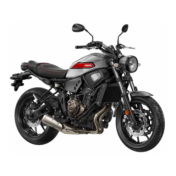
Summary of Contents for Yamaha XSR MTM690
- Page 1 Read this manual carefully before operating this vehicle. OWNER’S MANUAL MTM690 MTM690-U B34-F8199-E0...
- Page 2 EAU69860 Read this manual carefully before operating this vehicle. This manual should stay with this vehicle if it is sold. YAMAHA MOTOR ELECTRONICS CO., LTD. 1450-6, Mori, Mori-machi, Shuchi-gun, Shizuoka-ken, 437-0292 Japan DECLARATION of CONFORMITY Product: IMMOBILIZER Model: 1WS-00 Supplied by...
- Page 3 Welcome to the Yamaha world of motorcycling! As the owner of the MTM690/MTM690-U, you are benefiting from Yamaha’s vast experience and newest technology re- garding the design and manufacture of high-quality products, which have earned Yamaha a reputation for dependability.
-
Page 4: Important Manual Information
Important manual information EAU10134 Particularly important information is distinguished in this manual by the following notations: This is the safety alert symbol. It is used to alert you to potential personal injury hazards. Obey all safety messages that follow this symbol to avoid possible injury or death. - Page 5 Important manual information EAUM1013 MTM690/MTM690-U OWNER’S MANUAL ©2015 by MBK INDUSTRIE 1st edition, July 2015 All rights reserved Any reprinting or unauthorized use without the written permission of MBK INDUSTRIE is expressly prohibited. Printed in France.
-
Page 6: Table Of Contents
Table of contents Safety information......1-1 For your safety – pre-operation Adjusting the clutch lever free checks ..........4-1 play..........6-19 Description ........2-1 Checking the brake lever free Left view ......... 2-1 Operation and important riding play..........6-19 Right view........2-2 points ..........5-1 Brake light switches ..... - Page 7 Table of contents Replacing the auxiliary light bulb ...........6-35 Tail/brake light.......6-35 Replacing a turn signal light bulb ..........6-36 License plate light ......6-36 Supporting the motorcycle....6-37 Troubleshooting ......6-37 Troubleshooting charts ....6-39 Motorcycle care and storage ..7-1 Matte color caution ......7-1 Care ..........7-1 Storage ..........7-3 Specifications........8-1 Consumer information .....9-1...
-
Page 8: Safety Information
Safety information Never operate a motorcycle with- pears to be very effective in reduc- EAU1028B out proper training or instruction. ing the chance of this type of Take a training course. Beginners accident. Be a Responsible Owner should receive training from a cer- Therefore: As the vehicle’s owner, you are re- tified instructor. - Page 9 Safety information Many accidents involve inexperi- • Always signal before turning or Protective Apparel enced operators. In fact, many op- changing lanes. Make sure that The majority of fatalities from motorcy- erators who have been involved in other motorists can see you. cle accidents are the result of head in- ...
- Page 10 Safety information Do not run engine outdoors where Avoid Carbon Monoxide Poisoning When loading within this weight limit, All engine exhaust contains carbon engine exhaust can be drawn into keep the following in mind: Cargo and accessory weight monoxide, a deadly gas.
- Page 11 Yamaha accessories, which are avail- performed to your vehicle that change able only from a Yamaha dealer, have any of the vehicle’s design or operation should be kept to a minimum. been designed, tested, and approved characteristics can put you and others •...
- Page 12 Safety information Check that the fuel cock (if operator and may limit control ability, therefore, such accesso- equipped) is in the “OFF” position ries are not recommended. and that there are no fuel leaks. Use caution when adding electri- ...
-
Page 13: Description
Description EAU10411 Left view 9 8 7 1. Canister (page 6-9) 9. Coolant reservoir (page 6-12) 2. Seat lock (page 3-19) 3. Owner’s tool kit (page 6-2) 4. Shift pedal (page 3-14) 5. Engine oil filler cap (page 6-9) 6. Engine oil drain bolt (page 6-9) 7. -
Page 14: Right View
Description EAU10421 Right view 1. Main fuse (page 6-31) 9. Rear brake light switch (page 6-20) 2. Fuse box (page 6-31) 10.Rear brake fluid reservoir (page 6-21) 3. Battery (page 6-29) 4. Shock absorber assembly spring preload adjusting ring (page 3-21) 5. -
Page 15: Controls And Instruments
Description EAU10431 Controls and instruments 1. Clutch lever (page 3-13) 2. Left handlebar switches (page 3-12) 3. Multi-function meter unit (page 3-6) 4. Front brake fluid reservoir (page 6-21) 5. Right handlebar switches (page 3-12) 6. Throttle grip (page 6-15) 7. -
Page 16: Instrument And Control Functions
Do not expose any key to exces- cess, take the vehicle along with all three keys to a Yamaha dealer to have sively high temperatures. Do not place any key close to them re-registered. Do not use the key with the red bow for driving. -
Page 17: Main Switch/Steering Lock
Instrument and control functions Keep other immobilizer system EAU10474 EAU38531 Main switch/steering lock keys away from the main switch All electrical circuits are supplied with as they may cause signal inter- power; the meter lighting, taillight, li- ference. cense plate light and auxiliary light come on, and the engine can be start- ed. - Page 18 Instrument and control functions The steering must be locked before the EAU10686 LOCK key can be turned to “ ”. The steering is locked and all electrical If the steering will not lock, try turning ECA20760 systems are off. The key can be re- the handlebars back to the right slight- NOTICE moved.
-
Page 19: Indicator Lights And Warning Lights
High beam indicator light “ ” is correct, immediately turn the en- This indicator light comes on when the gine off and have a Yamaha dealer high beam of the headlight is switched check the vehicle. EAU59962 If the warning light does not go off after Oil pressure warning light “... - Page 20 The ABS may not work correctly. If any monitoring the engine. If this occurs, go off. of the above occurs, have a Yamaha have a Yamaha dealer check the vehi- If the warning light does not come on dealer check the system as soon as cle.
-
Page 21: Multi-Function Meter Unit
6. Fuel meter try starting the engine with the or if the indicator light remains on, have standard keys. a Yamaha dealer check the electrical 4. If one or both of the standard keys circuit. do not start the engine, take the... - Page 22 Instrument and control functions odometer mode or a tripmeter Red zone: 10000 r/min and above EWA12423 WARNING mode, and then press the bottom set button for three seconds. Be sure to stop the vehicle before Fuel meter making any setting changes to the multi-function meter unit.
- Page 23 Instrument and control functions Select the transmission gear that and “ ” will flash repeatedly. If this oc- Multi-function display curs, have a Yamaha dealer check the is appropriate for the vehicle vehicle. speed. Eco indicator Transmission gear display ZAUM1334 1.
- Page 24 Instrument and control functions The tripmeters show the distance trav- stantaneous fuel consumption “km/L”, to switch the display between the vari- eled since they were last reset. “L/100 km” or “MPG”, average fuel ous tripmeter, odometer, and fuel con- consumption “AVE_ _._ km/L”, “AVE_ sumption modes in the following order: _._ L/100 km”...
- Page 25 Instrument and control functions “AVE_ _._ MPG” : The average Instantaneous fuel consumption distance that can be traveled on If traveling at speeds under 20 km/h 1.0 Imp.gal of fuel. (12 mi/h), “_ _._” is displayed. To switch the average fuel consump- tion display settings, push the bottom Average fuel consumption set button for two seconds.
- Page 26 Instrument and control functions This display shows the coolant tem- This display shows the air temperature The clock displays time in 12-hour for- perature from 40 °C to 116 °C in 1 °C from –9 °C to 99 °C in 1 °C increments. mat.
-
Page 27: Handlebar Switches
Instrument and control functions Brightness control 5. Push the bottom set button to EAU1234H Handlebar switches confirm the selected brightness level and exit the brightness con- Left trol mode. There are 6 brightness level settings. ZAUM1341 1. Brightness level display The brightness level of the multi-func- 1. -
Page 28: Clutch Lever
Instrument and control functions Set this switch to “ ” to stop the en- EAU12351 EAU12822 Pass switch “ ” Clutch lever gine in case of an emergency, such as Press this switch to flash the headlight. when the vehicle overturns or when the throttle cable is stuck. -
Page 29: Shift Pedal
Instrument and control functions EAU12872 EAU26825 EAU12944 Shift pedal Brake lever Brake pedal The brake lever is located on the right side of the handlebar. To apply the front brake, pull the lever toward the throttle grip. ZAUM1342 1. Shift pedal 1. -
Page 30: Abs
Instrument and control functions EAU63040 The ABS performs a self-diagno- The Yamaha ABS (Anti-lock Brake sis test each time the vehicle first System) features a dual electronic con- starts off after the key is turned to trol system, which acts on the front and “ON”... -
Page 31: Fuel Tank Cap
Instrument and control functions EAU13075 EAU13222 Fuel tank cap Fuel The fuel tank cap cannot be closed un- Make sure there is sufficient gasoline in less the key is in the lock. In addition, the tank. the key cannot be removed if the cap is EWA10882 WARNING not properly closed and locked. - Page 32 EWA15152 as well as to the exhaust system. WARNING Gasoline is poisonous and can Your Yamaha engine has been de- cause injury or death. Handle gaso- signed to use premium unleaded gas- line with care. Never siphon gasoline oline with a research octane number of by mouth.
-
Page 33: Fuel Tank Breather Hose And Overflow Hose
Instrument and control functions EAU55512 EAU13434 ECA10702 Fuel tank breather hose and Catalytic converter NOTICE overflow hose This model is equipped with a catalytic Use only unleaded gasoline. The use converter in the exhaust system. of leaded gasoline will cause unre- EWA10863 pairable damage to the catalytic WARNING... -
Page 34: Seat
Instrument and control functions EAUM3740 EAUM3640 Seat Helmet holding cable A helmet holding cable is located un- To remove the seat der the seat. Use this cable in conjunc- Insert the key into the seat lock, turn it tion with the screwdriver to secure a counterclockwise, and then pull the helmet to the vehicle. - Page 35 Instrument and control functions driver in its original position, and then place the helmet holding ca- ble under the seat holder. ZAUM1360 ZAUM1361 1. Helmet holding cable 1. Helmet strap buckle 2. Screwdriver 2. Helmet holding cable 3. Holder 3. Screwdriver ZAUM1362 1.
-
Page 36: Adjusting The Shock Absorber Assembly
Spring preload setting: sembly yourself. Take the shock the adjusting ring in direction (a). To Minimum (soft): absorber assembly to a Yamaha decrease the spring preload and there- dealer for any service. by soften the suspension, turn the ad- Standard: justing ring in direction (b). -
Page 37: Sidestand
EAU15306 EAU57950 Sidestand Ignition circuit cut-off system Yamaha dealer repair it if it does not The sidestand is located on the left The ignition circuit cut-off system function properly. side of the frame. Raise the sidestand... - Page 38 Instrument and control functions WARNING With the engine turned off: 1. Move the sidestand down. If a malfunction is noted, have a Yamaha 2. Make sure that the start/engine stop switch is set to “ ”. dealer check the system before riding.
-
Page 39: Auxiliary Dc Connector
Instrument and control functions EAU70640 Auxiliary DC connector This vehicle is equipped with an auxil- iary DC connector. Consult your Yamaha dealer before installing any accessories. 3-24... -
Page 40: For Your Safety - Pre-Operation Checks
• If necessary, add recommended coolant to specified level. 6-12 • Check cooling system for leakage. • Check operation. • If soft or spongy, have Yamaha dealer bleed hydraulic system. • Check brake pads for wear. Front brake • Replace if necessary. - Page 41 • Make sure that operation is smooth. • Check throttle grip free play. Throttle grip 6-15, 6-25 • If necessary, have Yamaha dealer adjust throttle grip free play and lubricate ca- ble and grip housing. • Make sure that operation is smooth. Control cables 6-25 •...
- Page 42 • Tighten if necessary. Instruments, lights, signals • Check operation. — and switches • Correct if necessary. • Check operation of ignition circuit cut-off system. Sidestand switch 3-22 • If system is not working correctly, have Yamaha dealer check vehicle.
-
Page 43: Operation And Important Riding Points
a lean angle sensor to stop the en- The transmission is in the neutral understand, ask your Yamaha dealer. gine in case of a turnover. In this EWA10272 position. -
Page 44: Shifting
3-4 neutral position. The neutral indi- for the corresponding warning cator light should come on. If not, and indicator light circuit check. ask a Yamaha dealer to check the After going off once, the oil ZAUM1346 electrical circuit. pressure... - Page 45 Operation and important riding points 4. At the recommended shift points clutch lever in, use the brakes to ECA10261 NOTICE shown in the following table, close slow the motorcycle, and continue Even with the transmission in the throttle, and at the same time, to downshift as necessary.
-
Page 46: Tips For Reducing Fuel Consumption
Operation and important riding points EAU58280 EAU16811 EAU16842 Recommended shift points Tips for reducing fuel con- Engine break-in The recommended shift points during sumption There is never a more important period acceleration and deceleration are in the life of your engine than the period Fuel consumption depends largely on shown in the table below. -
Page 47: Parking
Yamaha dealer check the vehi- touch them and be burned. cle. Do not park on a slope or on soft... -
Page 48: Periodic Maintenance And Adjustment
To avoid possible burns, let tivities incorrectly may increase brake components cool before your risk of injury or death during touching them. service or while using the vehicle. If you are not familiar with vehicle ser- vice, have a Yamaha dealer perform service. -
Page 49: Owner's Tool Kit
If you do not have the tools or experi- ence required for a particular job, have a Yamaha dealer perform it for you. -
Page 50: Periodic Maintenance Chart For The Emission Control System
From 50000 km (30000 mi), repeat the maintenance intervals starting from 10000 km (6000 mi). Items marked with an asterisk should be performed by a Yamaha dealer as they require special tools, data and tech- nical skills. -
Page 51: General Maintenance And Lubrication Chart
Periodic maintenance and adjustment EAU1770M General maintenance and lubrication chart ODOMETER READING ANNUAL ITEM CHECK OR MAINTENANCE JOB 1000 km 10000 km 20000 km 30000 km 40000 km CHECK (600 mi) (6000 mi) (12000 mi) (18000 mi) (24000 mi) √ 1 * Air filter element •... - Page 52 Periodic maintenance and adjustment ODOMETER READING ANNUAL ITEM CHECK OR MAINTENANCE JOB 1000 km 10000 km 20000 km 30000 km 40000 km CHECK (600 mi) (6000 mi) (12000 mi) (18000 mi) (24000 mi) • Check operation and for exces- √ √...
- Page 53 Periodic maintenance and adjustment ODOMETER READING ANNUAL ITEM CHECK OR MAINTENANCE JOB 1000 km 10000 km 20000 km 30000 km 40000 km CHECK (600 mi) (6000 mi) (12000 mi) (18000 mi) (24000 mi) • Check operation and for oil leak- √...
- Page 54 Periodic maintenance and adjustment EAU18681 Air filter • This model’s air filter is equipped with a disposable oil-coated paper element, which must not be cleaned with com- pressed air to avoid damaging it. • The air filter element needs to be replaced more frequently when riding in unusually wet or dusty areas. ...
-
Page 55: Checking The Spark Plugs
1/2 turn past finger tight. However, the Yamaha dealer. Since heat and depos- with a wire thickness gauge and, if spark plug should be tightened to the its will cause any spark plug to slowly necessary, adjusted to specification. -
Page 56: Canister
Periodic maintenance and adjustment EAU36111 EAU60471 Canister Engine oil and oil filter car- tridge The engine oil level should be checked before each ride. In addition, the oil must be changed and the oil filter car- tridge replaced at the intervals speci- fied in the periodic maintenance and lubrication chart. - Page 57 Make sure that the O-ring is properly An oil filter wrench is available at a seated. 1. Engine oil drain bolt Yamaha dealer. 2. Gasket 7. Install the new oil filter cartridge 6. Apply a thin coat of clean engine...
- Page 58 17 Nm (1.7 m·kgf, 12 ft·lbf) ECA11621 is correct, immediately turn the en- NOTICE gine off and have a Yamaha dealer 8. Install the engine oil drain bolt and In order to prevent clutch slip- check the vehicle. its new gasket, and then tighten page (since the engine oil also 11.
-
Page 59: Coolant
2. Check the coolant level in the corrosion. If water has been coolant reservoir. added to the coolant, have a Yamaha dealer check the anti- The coolant should be between the freeze content of the coolant as minimum and maximum level marks. - Page 60 Periodic maintenance and adjustment soon as possible, otherwise the 5. Remove the coolant reservoir cap. effectiveness of the coolant will be reduced. [ECA10473] Coolant reservoir capacity (up to the maximum level mark): 0.25 L (0.26 US qt, 0.22 Imp.qt) EAU59863 To change the coolant ZAUM1347 1.
- Page 61 Antifreeze/water mixture ratio: its gasket to drain the coolant from the vehicle for coolant leakage. If the cooling system. coolant is leaking, have a Yamaha Recommended antifreeze: High-quality ethylene glycol anti- dealer check the cooling system. freeze containing corrosion inhibi-...
-
Page 62: Replacing The Air Filter Element And Cleaning The Check Hose
Periodi- 1. Remove the air filter check hose cally check the throttle grip free play under the air filter case. and, if necessary, have a Yamaha deal- er adjust it. ZAUM1348 1. Air filter check hose... -
Page 63: Valve Clearance
Tire air pressure (measured on cold from occurring, the valve clearance small area of road contact. Therefore, it tires): must be adjusted by a Yamaha dealer is essential to maintain the tires in good Front: 225 kPa (2.25 kgf/cm², 33 psi) - Page 64 “broken used or have only been used occasion- wall is cracked, have a Yamaha dealer in” for it to develop its optimal ally. Cracking of the tread and sidewall replace the tire immediately.
-
Page 65: Cast Wheels
If any damage is found, have high-speed ride. high speeds. a Yamaha dealer replace the Brand-new tires can have a rel- After extensive tests, only the tires list- wheel. Do not attempt even the... -
Page 66: Adjusting The Clutch Lever Free Play
The clutch lever free play should mea- brake lever end. If there is free play, rection (b). sure 5.0–10.0 mm (0.20–0.39 in) as have a Yamaha dealer inspect the shown. Periodically check the clutch brake system. lever free play and, if necessary, adjust... -
Page 67: Brake Light Switches
The front and rear brake pads must be should come on just before braking checked for wear at the intervals spec- takes effect. If necessary, have a ified in the periodic maintenance and Yamaha dealer adjust the brake light lubrication chart. switches. EAU36891 Front brake pads ZAUM1349 1. -
Page 68: Checking The Brake Fluid Level
Rear brake EAU40262 Checking the brake fluid level Yamaha dealer replace the brake pads Before riding, check that the brake fluid as a set. is above the minimum level mark. Check the brake fluid level with the top... -
Page 69: Changing The Brake Fluid
EAU22733 Changing the brake fluid id; otherwise, the rubber seals Yamaha dealer check the cause before Have a Yamaha dealer change the further riding. may deteriorate, causing leak- brake fluid at the intervals specified in age. -
Page 70: Drive Chain Slack
To adjust the drive chain slack turn the adjusting nut at each end 3. Push down on the drive chain un- Consult a Yamaha dealer before ad- of the swingarm in direction (b), der the end of the drive chain justing the drive chain slack. -
Page 71: Cleaning And Lubricating The Drive Chain
Periodic maintenance and adjustment occurring, keep the drive chain EAU23026 Cleaning and lubricating the slack within the specified limits. drive chain [ECA23070] The drive chain must be cleaned and lubricated at the intervals specified in the periodic maintenance and lubrica- tion chart, otherwise it will quickly wear out, especially when riding in dusty or wet areas. -
Page 72: Checking And Lubricating The Cables
Yamaha dealer at the intervals cated if necessary. If a cable is specified in the periodic maintenance damaged or does not move smoothly, chart. -
Page 73: Checking And Lubricating The Brake And Shift Pedals
Periodic maintenance and adjustment EAU44276 EAU23144 Recommended lubricant: Checking and lubricating the Checking and lubricating the Lithium-soap-based grease brake and shift pedals brake and clutch levers The operation of the brake and shift The operation of the brake and clutch pedals should be checked before each levers should be checked before each ride, and the pedal pivots should be lu-... -
Page 74: Checking And Lubricating The Sidestand
The operation of the sidestand should The pivoting points of the rear suspen- be checked before each ride, and the sion must be lubricated by a Yamaha sidestand pivot and metal-to-metal dealer at the intervals specified in the contact surfaces should be lubricated periodic maintenance and lubrication if necessary. -
Page 75: Lubricating The Swingarm Pivots
The swingarm pivots must be lubricat- face and hold it in an upright posi- fork does not operate smoothly, ed by a Yamaha dealer at the intervals tion. WARNING! To avoid injury, have a Yamaha dealer check or re- specified in the periodic maintenance securely support the vehicle so pair it. -
Page 76: Checking The Steering
If any free ways shield your eyes when smoothly, have a Yamaha dealer play can be felt, have a Yamaha working near batteries. In case check the wheel bearings. dealer check or repair the steer- of contact, administer the fol- ing. - Page 77 4. Remove the battery cover by re- To charge the battery drogen gas. Therefore, keep moving the bolts. Have a Yamaha dealer charge the bat- tery as soon as possible if it seems to sparks, flames, cigarettes, etc., away from the battery and pro- have discharged.
-
Page 78: Replacing The Fuses
Periodic maintenance and adjustment 2. If the battery will be stored for 7. Install the seat holder by installing EAUM3670 Replacing the fuses more than two months, check it at the bolts, and then tighten the The main fuse and the fuse boxes are least once a month and fully bolts to the specified torque. - Page 79 Periodic maintenance and adjustment 9 10 1 2 3 4 5 ZAUM1378 ZAUM1380 1. Diagnostic connector 1. Starter relay cover 1. Ignition fuse 2. Bolt 2. Fuse box 2. Signaling system fuse 3. Spare main fuse 3. Headlight fuse 4. Main fuse 4.
-
Page 80: Replacing The Headlight Bulb
If the headlight bulb possibly a fire. 4. If the fuse immediately blows [EWA15132] burns out, replace it as follows. again, have a Yamaha dealer ECA10651 Specified fuses: check the electrical system. NOTICE Main fuse: 5. - Page 81 5. Install the headlight bulb cover, and then connect the coupler. 6. Install the headlight unit by install- ing the bolts. 7. Have a Yamaha dealer adjust the headlight beam if necessary. ZAUM1382 1. Do not touch the glass part of the bulb.
-
Page 82: Replacing The Auxiliary Light Bulb
If the auxiliary light bulb burns out, re- If the tail/brake light does not come on, place it as follows. have a Yamaha dealer check it. 1. Remove the headlight unit. (See page 6-33.) 2. Remove the auxiliary light bulb... -
Page 83: Replacing A Turn Signal Light Bulb
Replacing a turn signal light License plate light bulb If the license plate light does not come on, have a Yamaha dealer check the 1. Remove the turn signal light lens electrical circuit or replace the bulb. by removing the screw. -
Page 84: Supporting The Motorcycle
However, should your motorcycle To service the front wheel require any repair, take it to a Yamaha 1. Stabilize the rear of the motorcy- dealer, whose skilled technicians have cle by using a motorcycle stand... - Page 85 Periodic maintenance and adjustment heaters or furnaces. Gasoline or gasoline vapors can ignite or ex- plode, causing severe injury or prop- erty damage. 6-38...
-
Page 86: Troubleshooting Charts
Remove the spark plugs and check the electrodes. The engine does not start. Have a Yamaha dealer check the vehicle. Check the compression. 4. Compression The engine does not start. There is compression. - Page 87 Start the engine. If the engine overheats again, have a The coolant level Yamaha dealer check and repair the cooling system. is OK. If coolant is not available, tap water can be temporarily used instead, provided that it is changed to the recommended cool- ant as soon as possible.
-
Page 88: Motorcycle Care And Storage
Some models are equipped with matte colored finished parts. Be ble. Rust and corrosion can develop Cleaning sure to consult a Yamaha dealer for even if high-quality components are ECA10773 NOTICE used. A rusty exhaust pipe may go un-... - Page 89 Motorcycle care and storage off any detergent residue using shield. Test the product on a plenty of water, as it is harmful small hidden part of the wind- Salt sprayed on roads in the winter to plastic parts. shield to make sure that it does may remain well into spring.
-
Page 90: Storage
EWA11132 poorly ventilated room or cover- WARNING ing it with a tarp, while it is still Consult a Yamaha dealer for ad- Contaminants on the brakes or tires wet, will allow water and humid- can cause loss of control. - Page 91 Motorcycle care and storage 2. Fill up the fuel tank and add fuel e. Remove the spark plug caps stabilizer (if available) to prevent from the spark plugs, and then Make any necessary repairs before the fuel tank from rusting and the install the spark plugs and the storing the motorcycle.
-
Page 92: Specifications
Specifications Dimensions: Engine oil: Spark plug(s): Overall length: Recommended brand: Manufacturer/model: 2075 mm (81.7 in) YAMALUBE NGK/LMAR8A-9 Overall width: SAE viscosity grades: Spark plug gap: 820 mm (32.3 in) 10W-40 0.8–0.9 mm (0.031–0.035 in) Overall height: Recommended engine oil grade: Clutch: 1130 mm (44.5 in) API service SG type or higher, JASO... - Page 93 Specifications Chassis: High-speed riding: Wheel travel: Front: 130 mm (5.1 in) Frame type: 225 kPa (2.25 kgf/cm², 33 psi) Rear suspension: Diamond Rear: Caster angle: Type: 250 kPa (2.50 kgf/cm², 36 psi) 25.0 ° Swingarm (link suspension) Front wheel: Trail: Spring/shock absorber type: 90 mm (3.5 in) Wheel type:...
- Page 94 Specifications Auxiliary light: Parking lighting fuse: 12 V, 5.0 W × 1 7.5 A License plate light: Radiator fan motor fuse: 12 V, 5.0 W × 1 10.0 A Meter lighting: Fuel injection system fuse: 10.0 A Neutral indicator light: ABS control unit fuse: 7.5 A High beam indicator light:...
-
Page 95: Consumer Information
These identification numbers are needed when registering the vehicle with the authorities in your area and when ordering spare parts from a Yamaha dealer. ZAUM1358 VEHICLE IDENTIFICATION NUMBER: 1. Vehicle identification number 1. Engine serial number... -
Page 96: Diagnostic Connector
(See page 3-19.) Re- cord the information on this label in the space provided. This information will be needed when ordering spare parts from a Yamaha dealer. ZAUM1370 1. Diagnostic connector The diagnostic connector is located as... -
Page 97: Index
Index Matte color, caution........ 7-1 Model label ..........9-1 ABS............3-15 Engine break-in ........5-4 Multi-function meter unit ......3-6 ABS warning light ........3-5 Engine oil and oil filter cartridge..... 6-9 Air filter element and check hose, Engine serial number ......9-1 replacing and cleaning ....... - Page 98 Index Tires ............6-16 Tool kit ............6-2 Troubleshooting ........6-37 Troubleshooting charts......6-39 Turn signal indicator lights......3-4 Turn signal light bulb, replacing....6-36 Turn signal switch .........3-13 Valve clearance........6-16 Vehicle identification number ....9-1 Wheel bearings, checking.....6-29 Wheels ..........6-18 10-2...
- Page 100 Original instructions MBK Industrie Z.I. de Rouvroy 02100 Saint Quentin PRINTED IN FRANCE 2015.09 (E)
Need help?
Do you have a question about the XSR MTM690 and is the answer not in the manual?
Questions and answers