Table of Contents
Advertisement
Quick Links
Download this manual
See also:
Owner's Manual
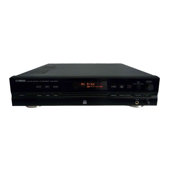
CDR-S1000
This manual has been provided for the use of authorized YAMAHA Retailers and their service personnel.
It has been assumed that basic service procedures inherant to the industry, and more specifically YAMAHA Products, are already
known and understood by the users, and have therefore not been restated.
WARNING:
IMPORTANT:
The data provided is believed to be accurate and applicable to the unit(s) indicated on the cover. The research, engineering, and
service departments of YAMAHA are continually striving to improve YAMAHA products. Modifications are, therefore, inevitable
and specifications are subject to change without notice or obligation to retrofit. Should any discrepancy appear to exist, please contact
the distributor's Service Division.
WARNING:
IMPORTANT:
CONTENTS
TO SERVICE PERSONNEL ................................... 1-2
REAR PANELS ............................................................. 3
SPECIFICATIONS ......................................................... 4
INTERNAL VIEW .......................................................... 5
DISASSEMBLY PROCEDURES ............................ 5-7
SERVICE CHECK PROCEDURES ........................ 8-9
TEST PROGRAM ................................................ 10-13
1 0 0 7 0 1
COMPACT DISC RECORDER
SERVICE MANUAL
IMPORTANT NOTICE
Failure to follow appropriate service and safety procedures when servicing this product may result in personal
injury, destruction of expensive components and failure of the product to perform as specified. For these reasons,
we advise all YAMAHA product owners that all service required should be performed by an authorized
YAMAHA Retailer or the appointed service representative.
The presentation or sale of this manual to any individual or firm does not constitute authorization, certification or
recognition of any applicable technical capabilities, or establish a principle-agent relationship of any form.
Static discharges can destroy expensive components. Discharge any static electricity your body may have accumu-
lated by grounding yourself to the ground buss in the unit (heavy gauge black wires connect to this buss).
Turn the unit OFF during disassembly and parts replacement. Recheck all work before you apply power to the unit.
IC DATA .............................................................. 14-24
PIN CONNECTION DIAGRAM ................................... 25
PRINTED CIRCUIT BOARD .............................. 26-33
BLOCK DIAGRAM .............................................. 34-35
SCHEMATIC DIAGRAM ..................................... 36-39
REMOTE CONTROL TRANSMITTER ....................... 40
PARTS LIST ........................................................ 41-50
CDR-S1000
Advertisement
Table of Contents

Related Manuals for Yamaha CDR-S1000


Summary of Contents for Yamaha CDR-S1000
-
Page 1: Table Of Contents
This manual has been provided for the use of authorized YAMAHA Retailers and their service personnel. It has been assumed that basic service procedures inherant to the industry, and more specifically YAMAHA Products, are already known and understood by the users, and have therefore not been restated. -
Page 2: To Service Personnel
CDR-S1000 TO SERVICE PERSONNEL 1. Critical Components Information AC LEAKAGE Components having special characteristics are marked Z WALL EQUIPMENT TESTER OR and must be replaced with parts having specifications equal UNDER TEST OUTLET EQUIVALENT to those originally installed. 2. Leakage Current Measurement (For 120V Models Only) - Page 3 CDR-S1000 Laser Diode Properties Optical pick-up Variable resistor (Do not turn) Material : GaAlAs Wavelength : 783 – 789 nm Emission duration : Continuous Laser output : Max. 44.6µW* ANSI Class : Class 1 * This output is the value measured at a distance of about 200 mm from the objective lens surface on the Optical Pick- up Block.
-
Page 4: Rear Panels
CDR-S1000 REAR PANELS U, C models A model B, G models... -
Page 5: Specifications
CDR-S1000 SPECIFICATIONS GENERAL INPUT/OUTPUT Model Compact disc recorder Line Output Output Level 2.0 Vrms Application discs CDs, CD-Rs for AUDIO, Output Impedance 990Ω CD-RWs for AUDIO Line Input Power Requirements Input Sensitivity 500m Vrms U, C models 120V AC 60Hz Input Impedance 24kΩ... -
Page 6: Internal View
• When sending back the defective CDR mechanical unit for repair, attach the disc which was used when the error occurred as necessary. However, Yamaha shall not be liable even if the data in the disc has become unreadable while the unit is being serviced/repaired. - Page 7 CDR-S1000 1. CDR Mechanical Unit Removal IDE cable a. Turn off the power and disconnect the power plug from a. Do not remove the cable from the female connector by the service outlet. pulling on the cable. CAUTION : Never disconnect any cable, remove any b.
- Page 8 CDR-S1000 3. CDR Mechanical Unit Installation CDR mechanical unit Usually called CDR/RW drive unit a. Before installing the CDR mechanical unit, check that Model name : ACRW100A the jumper pin on its rear panel is inserted in the MAS- TER jack.
-
Page 9: Service Check Procedures
CDR-S1000 SERVICE CHECK PROCEDURES When the main unit fails to operate. 1. Check the power supply voltage of ANALOG P.C.B. (2). Remarks Connector Pin No. Specified voltage 5.0 ± 0.25V W100 1pin (+5V) +5V power supply (Main P.C.B.) -27.0 ± 1.5V... - Page 10 CDR-S1000 SERVICE CHECK FLOW CHART Check the fault in the power Check the power supply section. supply Turn off the power to the drive section to check its condition. Disconnect the IDE cable. If operation fails, Turn on the power and the drive section is defective.
-
Page 11: Test Program
CDR-S1000 TEST PROGRAM When the test program is started, the memory and regis- ter are checked automatically. If nothing is found faulty, the AUDIO measurement mode is set. Starting the test program Short the connector CB7 (2P). POWER ON Main memory check Check the external memory (IC7). - Page 12 CDR-S1000 INSPECTION SPECIFICATIONS Instruments Required for Inspection • CD test disc (YEDS-18: TX911730) • CD-RW disc (TDK CD-RW AUDIO 74min [XA74]) • CD player with digital output (optical/coaxial) function (used as a digital signal generator) • AV amplifier with digital input (optical/coaxial) function (used as a D/A converter) •...
- Page 13 CDR-S1000 Check method and standard Step Mode Input signal Item Disc 1. Set the INPUT selector to the ANALOG posi- Audio measurement mode LINE IN (ANALOG) No disc A/D converter tion. (ATM mode) 1kHz, 20Hz, 20kHz 2. Apply a 1kHz, 500mVrms analog signal to the 500mVrms LINE IN (ANALOG).
- Page 14 CDR-S1000 Check method and standard Step Mode Input signal Item Disc Normal mode LINE IN (ANALOG) Recording XA74 1. Load the CD-RW disc (XA74). Playback 1kHz, 20Hz, 20kHz 2. Set the INPUT selector to the ANALOG posi- 370mVrms tion. 3. Apply a 1kHz, 370mVrms analog signal to the LINE IN (ANALOG).
-
Page 15: Ic Data
CDR-S1000 IC DATA IC5 : HD64F3039F18 P72/AN2 A17/P51 P73/AN3 A16/P50 P74/AN4 A15/P27 P75/AN5 A14/P26 P76/AN6 A13/P25 P77/AN7 A12/P24 AVCC A11/P23 P80/IRQ0 A10/P22 P81/IRQ1 A9/P21 P91/TXD1 A8/P20 P93/RXD1 P95/SCK1/IRQ5 A7/P17 PA0/TP0/TCLKA A6/P16 PA1/TP1/TCLKB A5/P15 PA2/TP2/TIOCA0/TCLKC A4/P14 PA3/TP3/TIOCB0/TCLKD A3/P13 A23/PA4/TP4/TIOCA1 A2/P12 A22/PA5/TP5/TIOCB1... - Page 16 CDR-S1000 IC5 : HD64F3039F18 PORT Name Function Address bus Address bus Address bus Address bus Address bus Address bus Address bus Address bus Address bus Address bus Address bus Address bus Address bus Address bus Address bus Address bus /WAIT...
- Page 17 CDR-S1000 IC8, 206 : YM3436DK DIR (Digital Format Interface Receiver) 24 26 28 25 17 15 14 13 12 31 DAUX HDLT EXTW SYSTEM DOUT CLOCK TSTN TIMING SYNC GENERATOR SYNC CTLP D DIN DATA CLOCK (N.C.) EIAJ (AES/EBU) CONTROLLER...
- Page 18 CDR-S1000 IC4 : FHIB31-70A ACDR IOCS16 ICLK HINTRQ6 LRCI HDMARQ BCKI DINS IORDY DOUTS PDIAG EXTW1 /HIOW SYNC1 /HIOR F641 /HDACK CSEL F2561 OCLK LRCO /HCS0 BCKO /HCS1 DASP CK33I MUTEA CK33O MUTEB RA16 RA15 RA14 RA13 RA12 RA11 RA10...
- Page 19 CDR-S1000 IC4 : FHIB31-70A ACDR PORT Name Function CPU interface address bus CPU interface address bus CPU interface address bus CPU interface address bus CPU interface address bus CPU interface address bus CPU interface address bus CPU interface address bus...
- Page 20 CDR-S1000 IC4 : FHIB31-70A ACDR PORT Name Function ICLK Clock output (N.C.) F2562 DIR1_256FS1 Clock input (256fs) DIR1_FS Word clock input (fs) F642 DIR1_64FS Clock input (64fs) SYNC2 DIR1_SYNC Synchronous signal input EXTW2 Word clock output (N.C.) DIP1 Extended input port for H8...
- Page 21 CDR-S1000 IC4 : FHIB31-70A ACDR PORT Name Function /HCS1 IDE_N_CS1 IDE interface chip select DASP IDE_N_DASP IDE interface active/slave CK33I CK33I Word clock CK33O CK33O Clock output Power supply RA16 CDR_RA16 External RAM address signal RA15 CDR_RA15 External RAM address signal...
- Page 22 CDR-S1000 IC205 : YSS228E-F DSP3 (Digital Audio Processor) DA16 DB12 DA17 DB11 DA18 DB10 ! 5 @ 2 @ 0 @ 1 ! 6 ! 7 i o ! 1 ! 2 ! 3 ! 4 DA19 DA20 DA21 DA22...
- Page 23 CDR-S1000 IC209 : XC95108-20PQ100C PLD (Programmable Logic Device) UBIT N_RAM N_DSP N_CDR N_UBD N_CDR_WAIT N_WRITE N_DS N_WR N_RD N_AS PORT Name Function GSR1 N_RESET Reset input Data bus GTS1 GTS1 GTS2 GTS2 + 5V power N WAIT N_WAIT WAIT output...
- Page 24 CDR-S1000 IC209 : XC95108-20PQ100C PLD (Programmable Logic Device) PORT Name Function Spare port Spare port + 5V power Data bus Data bus Data bus Data bus PLD_TDI Terminal for writing data PLD_TMS Terminal for writing data PLD_TCK Terminal for writing data...
- Page 25 CDR-S1000 IC209 : XC95108-20PQ100C PLD (Programmable Logic Device) PORT Name Function N CDR N_CDR ACDR chip select N UBD N_UBD ACDR chip select (for checking) N CDR WAIT N_CDR_WAIT ACDR WAIT signal input + 5V power N WRITE N_WRITE WRITE state signal...
-
Page 26: Pin Connection Diagram
CDR-S1000 PIN CONNECTION DIAGRAM µPC4570HA PST572CMT-R NJM4580L M5290P M5237L NJM2100L 1:VCC 2:GND 1 : VCC 3:OUT 2 : GND 3 : OUT NJM2904M-T1 TC74HCU04AF-TP1 AK4524VF LP621024DM-70LLQ M66004FP 24LC02BT HD74HC02FPEL W24258S-70LE-EL100 HD74HC86FP AD1893JST HD64F3039F18 XC95108-20PQ100C YSS228E-F YM3436DK FH1B31-70A Transistors DTA143EK 2SA933S (Q, R) -
Page 27: Printed Circuit Board
CDR-S1000 PRINTED CIRCUIT BOARD (Foil side) PANEL P. C. B. ( 1 ) DIRECT MUTE OPEN/ CLOSE STOP PLAY/ PAUSE W402 FROM : PANEL (3) W401 FROM : PANEL (2) PANEL P. C. B. ( 2 ) W400 FROM : MAIN (2) -
Page 28: Printed Circuit Board
CDR-S1000 PRINTED CIRCUIT BOARD (Foil side) PANEL P. C. B. ( 3 ) PANEL P. C. B. ( 5 ) REC LEVEL INPUT POWER PANEL P. C. B. ( 4 ) PHONES LEVEL... - Page 29 CDR-S1000 PRINTED CIRCUIT BOARD (Foil side) ANALOG P. C. B. ( 2 ) ANALOG P. C. B. ( 3 ) ANALOG P. C. B. ( 1 ) W200 FROM : ANALOG (3) C458 C459 ACH0 ACL0 ACL1 –VA ACH1 –VA SB–DATA...
- Page 30 CDR-S1000 PRINTED CIRCUIT BOARD (Foil side) q to @5 : TEST POINT WAVEFORMS (See page E36, 37/J32, 33) MAIN P. C. B. ( 1 ) ( Lead Type Device ) Semiconductor Location DIGITAL IN DIGITAL OUT Ref. No. Location COAXIAL...
- Page 31 CDR-S1000 PRINTED CIRCUIT BOARD (Foil side) MAIN P. C. B. ( 2 ) ( Lead Type Device ) MAIN P. C. B. ( 1 ) ( Surface Mount Device ) W400 FROM : PANEL (2) MAIN P. C. B. ( 2 )
-
Page 32: Block Diagram
CDR-S1000 BLOCK DIAGRAM FH1B31-70A ACDR DIGITAL OUT OPTICAL ATAPI COAXIAL CD-R/W DRIVE EXTERNAL WORD CLOCK XL200 IC207 IC206 DIGITAL IN IC201 AD1893JST YM3436D DRIVE WORD CLOCK OPTICAL DIR2 COAXIAL SRAM ACRW100A IC205 YSS228E-F DSP3 REC LEVEL ANALOG IC402 VR580 SRAM... - Page 33 CDR-S1000 The voltage value is measured during playback. SCHEMATIC DIAGRAM (MAIN P.C.B.) The waveform is measured while CD OPTICAL (1kHz) signal is recorded. Point @ 2 (Pin 111 of IC4) V : 2V/div, H : 10 msec/div DC, 1 : 1 probe Point !8 (Pin 62 of IC4 or Pin 63 of IC205) V : 2V/div, H : 5 µsec/div...
- Page 34 CDR-S1000 SCHEMATIC DIAGRAM (MAIN P.C.B.) Point q (Pin 4 of IC201) Point ! 5 (Pin 49 of IC205) V : 2V/div, H : 1 µsec/div V : 2V/div, H : 5 µsec/div DC, 1 : 1 probe DC, 1 : 1 probe...
- Page 35 CDR-S1000 SCHEMATIC DIAGRAM (MAIN & PANEL P.C.B.) -20.9 -20.9 P-E39/J35 FL DRIVER MAIN (2) SAME PAGE P-E36/J32 PHONES AMP SAME PAGE PANEL (2) -26.7 -20.9 -20.9 P-E39/J35 V1 : 14-BT-56GN -7.5 -8.5 -8.0 PATTERN AREA Point y (Pin 20 of IC830) V : 2V/div, H : 1 µsec/div...
- Page 36 CDR-S1000 SCHEMATIC DIAGRAM (ANALOG P.C.B.) IC400, 403 : NJM4580L IC401 : NJM2100L Dual OP-Amp – – A/D CONVERTER D/A CONVERTER -4.9 IC402 : AK4524VF -4.9 24bit 2ch ADC/24bit 2ch DAC VCOM AOUTR+ -5.0 AINR AOUTR– AINL DGND AINL AOUTL+ VREF AOUTL–...
-
Page 37: Schematic Diagram
CDR-S1000 REMOTE CONTROL TRANSMITTER SCHEMATIC DIAGRAM KI/O6 KI/O5 KI/O7 KI/O4 IED1 KI/O3 47µF S1/LED KI/O2 KI/O1 220Ω KI/O0 2.2Ω XOUT 3(V) RESET 3.64MHz CUSTOM DATA CUSTOM CUSTOM DATA DATA FUNCTION CODE CODE CODE CODE CODE CODE (HEX) (HEX) (BIN) (BIN) -
Page 38: Parts List
CDR-S1000 WARNING PARTS LIST Components having special characteristics are marked Z and must be replaced with parts having specifications equal to those originally installed. Carbon resistors (1/6W or 1/4W) are not included in the ELECTRICAL PARTS ELECTRICAL PARTS List. For the parts No. of the carbon resistors, refer to last page. - Page 39 CDR-S1000 P.C.B. PANEL & MAIN Schm Schm Ref. PART NO. Description Ref. PART NO. Description V4836900 P.C.B. PANEL V4837300 P.C.B. MAIN CB500 VB858600 CN.BS.PIN * CB1 V4325300 CN CB580 VB858700 CN.BS.PIN VL845000 CN.BS.PIN CB581 VB858500 CN.BS.PIN VP573800 CN.BS.PIN CB680 VP245600 CN * CB5 V4831400 CN.BS.PIN...
- Page 40 CDR-S1000 P.C.B. MAIN Schm Schm Ref. PART NO. Description Ref. PART NO. Description US061330 C.CE.M.CHP 33pF C206 US135100 C.CE.CHP 0.1uF US062100 C.CE.M.CHP 100pF C207 US135100 C.CE.CHP 0.1uF US062100 C.CE.M.CHP 100pF C208 VK679700 C.EL 100uF 6.3V US062100 C.CE.M.CHP 100pF C209 US135100 C.CE.CHP 0.1uF...
-
Page 41: Remote Control Transmitter
CDR-S1000 P.C.B. MAIN & ANALOG Schm Schm Ref. PART NO. Description Ref. PART NO. Description C261 US135100 C.CE.CHP 0.1uF IC830 XT828A00 IC M66004FP C262 US135100 C.CE.CHP 0.1uF VY657500 COIL.CHP 120uH C263 US135100 C.CE.CHP 0.1uF L200 Vi530800 TRANS.PULS 3PTD-001 C264 US135100 C.CE.CHP 0.1uF... - Page 42 CDR-S1000 P.C.B. ANALOG Schm Schm Ref. PART NO. Description Ref. PART NO. Description C416 VQ083000 C.EL 47uF C610 UJ668100 C.EL 100uF C417 VH053100 C.CE.TUBLR 0.1uF C611 UM416470 C.EL 4.7uF C418 VQ082700 C.EL 10uF C612 UR73A100 C.EL 10000uF C419 VQ083000 C.EL...
- Page 43 CDR-S1000 P.C.B. ANALOG CHIP RESISTORS Schm Schm Ref. PART NO. Description Ref. PART NO. Description Q406 VK432900 TR 2SD1915F S,T RD250000 R.CAR.CHP 0Ω 1/10W Q407 VK432900 TR 2SD1915F S,T RD253220 R.CAR.CHP 2.2Ω 1/10W Q600 iA093320 2SA933S Q,R RD254100 R.CAR.CHP 10Ω...
-
Page 44: Exploded View
CDR-S1000 EXPLODED VIEW 1-65 1-62 1-1 (5) 1-64 1-65 1-14 1-63 1-51 1-61 1-12 1-18 1-17 1-64 1-62 1-26 1-16 1-19 1-22 1-11 1-61 1-21 1-61 1-65 200-1 1-24 1-15 1-23 1-65 1-25... - Page 45 CDR-S1000 MECHANICAL PARTS Ref. PART NO. Description Remarks Markets * 1- 1 V4836900 P.C.B. ASS’Y PANEL * 1- 7 V5237300 FLEXIBLE FLAT CABLE 12P 150mm * 1- 8 V4868200 FLEXIBLE FLAT CABLE 18P 270mm * 1-11 V4725600 FRAME, FRONT * 1-12...
- Page 46 CDR-S1000 Ref. PART NO. Description Remarks Markets EK396010 BIND HEAD S-TITE SCREW FCRM3-BL EK365090 PW HEAD S-TITE SCREW 4x8-10 FCRM3-BL VQ057700 HEXAGONAL CAP NUT FNM3-3G EX604260 HEXAGONAL CAP NUT MFNI33 EP630210 BIND HEAD S-TITE SCREW ZMC2-BL VF617600 PAN HEAD P-TITE SCREW 2.6x8...
-
Page 47: Parts List
CDR-S1000 Parts List for Carbon Resistors Value 1/4W Type Part No. 1/6W Type Part No. Value 1/4W Type Part No. 1/6W Type Part No. 1.0 Ω 3100 3100 7100 10 kΩ 7100 HJ35 HF85 HF45 HF45 1.8 Ω 3180 7110 11 kΩ... - Page 48 CDR-S1000...
Need help?
Do you have a question about the CDR-S1000 and is the answer not in the manual?
Questions and answers