Yamaha CDR1000 Service Manual
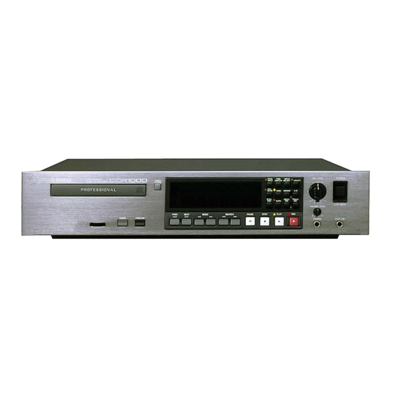
Professional audio cd recorder
Hide thumbs
Also See for CDR1000:
- Owner's manual (67 pages) ,
- Service manual (45 pages) ,
- Brochure & specs (4 pages)
Advertisement
Quick Links
QQ
3 7 63 1515 0
TE
L 13942296513
www
.
PA
011479
19991025-188000
http://www.xiaoyu163.com
PROFESSIONAL AUDIO CD RECORDER
CONTENTS
SPECIFICATIONS
PANEL LAYOUT
BLOCK DIAGRAM
WIRING
CIRCUIT BOARD LAYOUT
DISASSEMBLY PROCEDURE
LSI PIN DESCRIPTION
IC BLOCK DIAGRAM
CIRCUIT BOARDS
TEST PROGRAM
ERROR MESSAGES
PARTS LIST
x
ao
u163
OVERALL CIRCUIT DIAGRAM
y
i
http://www.xiaoyu163.com
2 9
8
SERVICE MANUAL
Q Q
3
6 7
1 3
1 5
................................................... 3
.............................................................. 6
co
.
9 4
2 8
0 5
8
2 9
9 4
2 8
.................................... 4
............................ 5
................. 7
.............................. 8
............................... 10
.................................. 12
....................................... 14
............................ 17/21
............................. 25
m
HAMAMATSU, JAPAN
1.52K-599
Printed in Japan '99.12
9 9
9 9
Advertisement

Related Manuals for Yamaha CDR1000


Summary of Contents for Yamaha CDR1000
- Page 1 http://www.xiaoyu163.com 3 7 63 1515 0 PROFESSIONAL AUDIO CD RECORDER SERVICE MANUAL L 13942296513 CONTENTS SPECIFICATIONS ........... 3 PANEL LAYOUT ........4 BLOCK DIAGRAM ......5 WIRING .............. 6 CIRCUIT BOARD LAYOUT ....7 DISASSEMBLY PROCEDURE ......8 LSI PIN DESCRIPTION .......
- Page 2 IMPOR TANT NOTICE This manual has been provided for the use of authorized Yamaha Retailers and their service personnel. It has been assumed that basic service procedures inherent to the industry, and more specifically Yamaha Products, are already known and under- stood by the users, and have therefore not been restated.
- Page 3 http://www.xiaoyu163.com 3 7 63 1515 0 PROTECTION OF EYES FROM LASER BEAM DURING SERVICING When checking the laser diode emission, keep your eyes more than 30 cm away from the objective lens. WARNING: LASER SAFETY This product contains a laser beam component. This component may emit invisible, as well as visible radiation, which may cause eye damage.
- Page 4 http://www.xiaoyu163.com 3 7 63 1515 0 L 13942296513 • This label is located on the interior. CAUTION : INVISIBLE LASER RADIATION WHEN OPEN. • Varningsanvisning för AVOID EXPOSURE TO BEAM. laserstrålning. Placerad VARNING : OSYNLIG LASERSTRÅLNING NÄR DENNA DEL ÄR i apparaten.
- Page 5 5˚ C to 35˚ C (41˚ F to 95˚ F) w w w Relative humidity 10%–95% u 1 6 3 Power cord, remote controller, batteries (size AA, R6, Accessories UM-3 x2), transportation pad, Owner’s Manual Options Yamaha FC5 footswitch http://www.xiaoyu163.com...
- Page 6 CDR1000 3 7 6 3 1 5 1 5 0 PANEL LAYOUT Front panel Remote Controller OPEN/CLOSE button REC MUTE button INPUT SELECT button POWER PEAK TIME INPUT REC LEVEL PROFESSIONAL AUDIO CD RECORDER OPEN/ HOLD DISPLAY SELECT UTILITY...
- Page 7 CDR1000 3 7 6 3 1 5 1 5 0 BLOCK DIAGRAM IC33 IC32 IC30 IC19 IC44 , 45 IC30 IC39 IC44 , 45 1 3 9 4 2 2 9 6 5 1 3 IC46 IC43 IC47 IC31...
- Page 8 CDR1000 3 7 6 3 1 5 1 5 0 WIRING Parts List Destination Connector Assembly Pin/Lenght MAIN-CN1 FP3/7-CN5 C & C 8P/L200 FRONT 250 MAIN-CN2 FP2/7-CN3 C & C 7P/L250 FRONT 260 C & C 5P/L250 FRONT 270...
- Page 9 CDR1000 3 7 63 1515 0 CIRCUIT BOARD LAYOUT MAIN CRW Unit L 13942296513 Power Transformer FP 2/7 FP 4/7 FP 7/7 FP 1/7 FP 3/7 FP 5/7 FP 6/7 u163 http://www.xiaoyu163.com...
-
Page 10: Disassembly Procedure
CDR1000 3 7 63 1515 0 DISASSEMBLY PROCEDURE Top Cover Remove the seven (7) screws marked [320] and remove the top cover by sliding it rearward. [320]:Bind Head Tapping Screw-B A3.0x8 MFZN2BL+BindB Tight (VP157000) 2. Circuit Boards and Units After removing the top cover, remove the following screw. - Page 11 CDR1000 3 7 6 3 1 5 1 5 0 〈 TOP VIEW 〉 CRW Unit 4-1. Remove the four (4) screws marked [250], and the angle can be removed. 4-2. Remove the two (2) screws marked [A] and push in...
- Page 12 CDR1000 3 7 6 3 1 5 1 5 0 LSI PIN DESCRIPTION YSS228E-F (XQ962D00) DSP3 (Digital Signal Processor) AK4520A-VF-E2 (XT802A00) DAC&ADC NAME FUNCTION NAME FUNCTION NAME FUNCTION NAME FUNCTION Ground Ground VREFH MCLK Master Clock Input Positive Voltage Reference Input, VA...
- Page 13 CDR1000 3 7 6 3 1 5 1 5 0 SM5844AF (XW097A00) Sample Converter HD64F3039F18 (XW700A00) CPU NAME FUNCTION NAME FUNCTION PIN NO. PIN NO. NAME FUNCTION NAME FUNCTION TIOCA3 A18/P52 Address bus OW20N Input data Output format setting*1...
- Page 14 CDR1000 3 7 6 3 1 5 1 5 0 HD74HC00FPEL (XP250A00) TC74HC04AF (XS993A00) TC74HC14AF-TP1(XD657A00) TC74HC4024AF(XT546A00) TC74HC573AF(XH224A00) SN74HC595NSR(XW108A00) TC74HCU04AF-TP1(XD660A00) IC4, IC7, IC24 IC25 IC11, IC58, IC59, IC60 IC29, IC50, IC66 IC6, IC52, IC65 Hex Inverter NAND COUNTER T-LATCCHES SHIFT REGIST...
- Page 15 CDR1000 3 7 63 1515 0 TC7W04FU(XQ805A00) M66004FP (XT828A00) INVERTER FL DRIVER DISPKAY CODE SERIAL CGROM REGISTER RECEIVE SEG00 (35BIT x 160) (8BIT x 16) CIRCUIT SDATA SEGMENT SEG26 OUTPUT SEG27 CIRCUIT CGRAM SEG35 (35BIT x 16) CORD/ COMMAND...
- Page 16 CDR1000 3 7 6 3 1 5 1 5 0 CIRCUIT BOARDS MAIN Circuit Board WORD CLOCK DIGITAL (AES/EBU) DIGITAL (COAXIAL) ANALOG IN ANALOG OUT PARALLEL +4dB -10dBV CN6: to CD-R/W CN5: to CD-R/W DRIVE UNIT CN9: to CD-R/W...
- Page 17 CDR1000 3 7 6 3 1 5 1 5 0 1 3 9 4 2 2 9 6 5 1 3 Pattern side w w w u 1 6 3 http://www.xiaoyu163.com...
- Page 18 CDR1000 3 7 6 3 1 5 1 5 0 FP Circuit Board FP 6/7 FP 1/7 CN8: to FOOT SW MAIN-CN12 Component side FP 4/7 CN6: to REC LEVEL MAIN-CN10 CN2: to MAIN-CN4 Component side FP 2/7 PAUSE...
- Page 19 CDR1000 3 7 6 3 1 5 1 5 0 FP Circuit Board FP 1/7 FP 6/7 Pattern side FP 4/7 Pattern side Pattern side FP 2/7 1 3 9 4 2 2 9 6 5 1 3 FP 3/7...
- Page 20 CDR1000 3 7 6 3 1 5 1 5 0 PS Circuit Board CN22: to AC IN CN21: to FP 7/7-CN9 CN104: to DM-CN7 1 3 9 4 2 2 9 6 5 1 3 CN105: to FP 1/7-CN1...
-
Page 21: Test Program
CDR1000 3 7 63 1515 0 TEST PROGRAM Unless otherwise specified, use the following volume and switch settings. REC LEVEL: Max. PHONES LEVEL: Max. GAIN SW: +4dB Connect the following load resistance to each output terminal. ANALOG OUT (L, R):... - Page 22 CDR1000 3 7 63 1515 0 D2 Key Switch Connect the FOOT SW to the FOOT SW jack and select this test program. The display will appear as shown below. D2: FOOT SW Turn on the FOOT SW. If the check result is OK, move to the next switch check. The switches are tested in the following order.
- Page 23 CDR1000 3 7 63 1515 0 D9 WORD CLOCK Input a 1 kHz, full-scale signal into the AES/EBS IN, and a 44.1 kHz word clock intothe WORD CLOCK terminal, check that a 1 kHz, full-scale signal is output from AES/EBS OUT.
- Page 24 CDR1000 3 7 63 1515 0 6. Recording Playback Distortion Factor Select ANALOG from the INPUT SELECT switch and press the REC key (REC stand-by state). Input a 1 kHz, +8 dB signal into ANALOG IN L and R and check that the distortion factor at ANALOG OUT L and R is less than 0.03%.
- Page 25 CDR1000 3 7 63 1515 0 L 13942296513 u163 http://www.xiaoyu163.com...
- Page 26 CDR1000 3 7 63 1515 0 L 13942296513 u163 http://www.xiaoyu163.com...
- Page 27 CDR1000 3 7 63 1515 0 L 13942296513 u163 http://www.xiaoyu163.com...
- Page 28 CDR1000 3 7 63 1515 0 L 13942296513 u163 http://www.xiaoyu163.com...
- Page 29 CDR1000 3 7 63 1515 0 ERROR MESSAGES If the CDR1000 displays an error message, follow the instructions below. Error Number Remarks 062900 062800 020401 023A02 023A03 052000 052400 020408 030C0A 052100 0409XX Change media or failure 056400 056401...
-
Page 30: Parts List
http://www.xiaoyu163.com 3 7 63 1515 0 PROFESSIONAL AUDIO CD RECORDER PARTS LIST CONTENTS OVERALL ASSEMBLY ..........2 FRONT ASSEMBLY ........4 ELECTRICAL PARTS ..........6 L 13942296513 Notes : DESTINATION ABBREVIATIONS A : Australian model M : South African model B : British model O : Chinese model C : Canadian model... - Page 31 CDR1000 3 7 63 1515 0 OVERALL ASSEMBLY 180a 180b L 13942296513 u163 Front assembly (See page 4) http://www.xiaoyu163.com...
- Page 32 CDR1000 3 7 63 1515 0 PART NO. DESCRIPTION REMARKS REF NO. RANK OVERALL ASSEMBLY CDR1000 J,U,V,H,W,B Overall Assembly (V4570900) Overall Assembly (V4571000) Overall Assembly (V4571100) Overall Assembly (V4571200) Earth Film (V521920) V 4 0 5 6 9 0 0...
- Page 33 CDR1000 3 7 63 1515 0 FRONT ASSEMBLY L 13942296513 u163 http://www.xiaoyu163.com...
- Page 34 CDR1000 3 7 63 1515 0 PART NO. DESCRIPTION REMARKS REF NO. RANK FRONT ASSEMBLY CDR1000 Front Assembly (V457240) Sub Chassis (V405790) AAX08680 Circuit Board FP 1/7 AAX08690 Circuit Board FP 2/7 AAX08700 Circuit Board FP 3/7 AAX08710 Circuit Board...
-
Page 35: Electrical Parts
CDR1000 3 7 63 1515 0 ELECTRICAL PARTS PART NO. DESCRIPTION REMARKS REF NO. RANK ELECTRICAL PARTS V 3 5 4 0 5 0 0 Circuit Board MAIN (XV958B0) AAX08680 Circuit Board FP 1/7 (XV959C0) AAX08690 Circuit Board FP 2/7... - Page 36 CDR1000 3 7 63 1515 0 PART NO. DESCRIPTION REMARKS REF NO. RANK V 3 1 2 3 6 0 0 Push Switch SKECAF PAUSE,STOP,PLAY,REC, V 3 1 2 3 6 0 0 Push Switch SKECAF PEAK HOLD,TIME DISPLAY,...
- Page 37 CDR1000 3 7 63 1515 0 PART NO. DESCRIPTION REMARKS REF NO. RANK XD657A00 TC74HC14AF-TP1 INVERTER XW092A00 TC74HC20AF NAND XP250A00 HD74HC00FPEL NAND XD657A00 TC74HC14AF-TP1 INVERTER XW092A00 TC74HC20AF NAND XT090A00 SRM2B256SLMX70 SRAM 256K IC10 XN241A00 TC74HC32AF IC11 XW108A00 SN74HC595NSR SHIFT REGISTER...
- Page 38 CDR1000 3 7 63 1515 0 PART NO. DESCRIPTION REMARKS REF NO. RANK VS133700 XLM Connector NC3MAH ANALOG OUT R JK10 VT696400 Holder, Cannon Connector VQ724900 Chip Inductance BK2125HM601-T VQ724900 Chip Inductance BK2125HM601-T VS740100 Chip Inductance BLM21B751S VQ724900 Chip Inductance...
- Page 39 CDR1000 3 7 63 1515 0 PART NO. DESCRIPTION REMARKS REF NO. RANK V J 9 0 0 5 0 0 Monolithic Ceramic Cap. C:304 VR326600 Mylar Cap. (chip) 0.022 C:309 VR329100 Mylar Cap. (chip) 0.001 C:305,306 VT896800 Electrolytic Cap.
- Page 40 CDR1000 3 7 63 1515 0 PART NO. DESCRIPTION REMARKS REF NO. RANK VU171900 Zener Diode UDZS5.1BTE-17 5.1V V 5 0 7 6 4 0 0 Circuit Board (XV960B00) V 3 5 4 0 6 0 0 Circuit Board...
- Page 41 CDR1000 3 7 63 1515 0 PART NO. DESCRIPTION REMARKS REF NO. RANK VR796000 Capacitor 0.1 250VAC C:21 V 5 0 9 0 3 0 0 Capacitor 2200P 250V C:127,128 U,H,B,W,V F I 3 8 3 4 7 0...
- Page 42 CDR1000 CIRCUIT DIAGRAM 1/3 ( MAIN1/3 ) CDR1000 3 7 6 3 1 5 1 5 0 1 3 9 4 2 2 9 6 5 1 3 w w w u 1 6 3 CDR1000 CDR1000 http://www.xiaoyu163.com...
- Page 43 CDR1000 CIRCUIT DIAGRAM 2/3 ( MAIN2/3 ) CDR1000 3 7 6 3 1 5 1 5 0 1 3 9 4 2 2 9 6 5 1 3 w w w u 1 6 3 CDR1000 CDR1000 http://www.xiaoyu163.com...
- Page 44 CDR1000 CIRCUIT DIAGRAM 3/3 ( MAIN3/3 , FP-1/3 , 2/3 , 3/3 , PS ) CDR1000 w w w CDR1000 CDR1000 http://www.xiaoyu163.com...
Need help?
Do you have a question about the CDR1000 and is the answer not in the manual?
Questions and answers