
Related Manuals for Toro 30410


Summary of Contents for Toro 30410
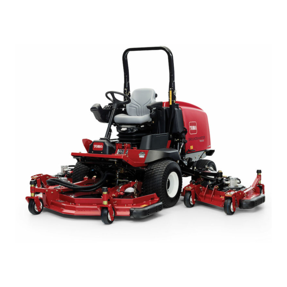
- Page 1 Form No. 3357-707 Rev B Groundsmaster® 4000-D Traction Unit Model No. 30410—Serial No. 2700000001 and Up Register your product at www.Toro.com Original Instructions (EN)
-
Page 2: Table Of Contents
Whenever you need service, genuine Toro parts, Before Operating....... 19 or additional information, contact an Authorized Starting and Stopping the Service Dealer or Toro Customer Service and have Engine ......28 the model and serial numbers of your product Checking the Interlock ready. - Page 3 Activating, Charging, and Inspecting and Sharpening the Connecting the Cutter Blade(s) ....56 Battery ......41 Correcting Cutting Unit Battery Care ........43 Mismatch ......57 Fuses..........43 Spark Arrestor Maintenance ...... 57 Drive System Maintenance......43 Servicing the Spark Arrestor Changing the Planetary Gear Drive Muffler......
-
Page 4: Safety
Safety ◊ inadequate braking; ◊ the type of machine is unsuitable for its This machine meets or exceeds CEN standard task; EN 836:1997, ISO standard 5395:1990, and ◊ lack of awareness of the effect of ANSI B71.4-2004 specifications in effect at the ground conditions, especially slopes;... - Page 5 accessories and attachments approved by the • When using any attachments, never direct manufacturer. discharge of material toward bystanders nor allow anyone near the machine while in • Check that operators presence controls, operation. safety switches, and shields are attached and functioning properly.
-
Page 6: Toro Mower Safety
The following list contains safety information an open flame or spark. specific to Toro products or other safety • Allow the engine to cool before storing in any information that you must know that is not enclosure and do not store near flame. -
Page 7: Maintenance And Storage
• Wearing safety shoes and long pants is advisable • Do not mow on wet grass. Reduced traction and required by some local ordinances and could cause sliding. insurance regulations. • Do not try to stabilize the machine by putting •... -
Page 8: Sound Pressure Level
This unit has an equivalent continuous A-weighted • If major repairs are ever needed or if assistance sound power level at the operator ear of 105 is desired, contact an Authorized Toro dBA/1 pW, based on measurements of identical Distributor. - Page 9 100-5624 100-5623 1. Height of cut adjustment 1. Low height of cut 2. High height of cut adjustment adjustment 100-5693 1. Height of cut adjustment 100-5694 1. Height of cut adjustment 100-6578 1. Entanglement hazard, belt—do not operate the machine with the shields or guards removed;...
- Page 10 104-2277 104-2277 1. To lock the parking brake, 4. Read the Operator’s 104-3599 latch the pedals together, Manual. apply the brake pedals, and 1. Do not step here. pull up on the knob. 2. Traction pedal 2. To unlock the parking 5.
- Page 11 104-8325 1. Lock/unlock the cutting unit service lock. 106-6753 1. Engine coolant under pressure 2. Explosion hazard—read the Operator’s Manual. 3. Warning—do not touch the hot surface. 4. Warning—read the Operator’s Manual. 112-9118 1. Warning—read the Operator’s Manual. 2. Warning—lock the parking brake, stop the engine, and remove the ignition key before leaving the machine.
- Page 12 110-3286 1. Power outlet 4. Power Take Off (PTO) 2. Seat switch 5. Starter solenoid 3. Ignition switch 6. Light Kit 106-6764 1. To start the engine, move the traction pedal to Neutral, press the brake pedal, move the throttle lever to Fast, turn the ignition key to On, and then turn the ignition key to Start;...
- Page 13 104-8336 1. Read the Operator’s Manual.
-
Page 14: Setup
Setup Loose Parts Use the chart below to verify that all parts have been shipped. Step Description Qty. Seat kit (obtain separately) Seat suspension kit (obtain separately) Manual tube Install the seat, seat belt, and R-clamp manual tube. Seat belt Bolt Lock washer –... -
Page 15: Greasing The Machine
1. Mount the manual tube to the seat suspension Step with the 2 R-clamps included in loose parts. 2. Install the seat belt to each side of the seat with a bolt and lock washer, supplied in loose parts. Important: Make sure that the seat Reading the Manuals and switch wire is connected to the seat switch Viewing the DVD... -
Page 16: Product Overview
Product Overview pedal. For no load, maximum ground speed, fully press the pedal while the throttle is in Fast. To stop, reduce your foot pressure on the traction pedal and allow it to return to the center position. Important: The speed limiter screw must stop the traction pedal before the pump reaches full stroke or damage to the pump may occur. -
Page 17: Pto Switch
Glow Plug Indicator Light PTO Switch When lit, the glow plug indicator light (Figure 2) The PTO switch (Figure 4) has three positions: On indicates that the glow plugs are on. (engage), Neutral, and Off (disengage). Carefully lift and push the PTO switch forward to the On Engine Temperature Gauge position to start the implement or cutting unit blades. - Page 18 A selection of Toro approved attachments and accessories are available for use with the machine to enhance and expand its capabilities. Contact your Authorized Service Dealer or Distributor or go to www.Toro.com for a list of all approved attachments and accessories.
-
Page 19: Specifications
5. Install the oil fill cap and dipstick. 6. Close the engine cover and secure it with the Toro Premium Engine Oil is available from your latches. distributor in either 15W-40 or 10W-30 viscosity. See the parts catalog for part numbers. -
Page 20: Filling The Fuel Tank
Toro Premium All Season Hydraulic Fluid top of the tank, not the filler neck, with No. 2 (Available in 5 gallon pails or 55 gallon drums. See diesel fuel. Then install the cap. parts catalog or Toro distributor for part numbers.) - Page 21 This is vegetable-oil based biodegradable oil tested quality SAE 85W-140 gear lube as a replacement. and approved by Toro for this model. This fluid is The capacity of the system is approximately 16 oz not as resistant to high temperatures as standard (0.5 l).
- Page 22 before the engine is first started and every 400 hours thereafter. The capacity is 80 oz (2.4 l). Visually inspect for leaks daily. 1. Position the machine on a level surface. 2. Remove a check plug from one end of the axle (Figure 12) and make sure that the lubricant is up to the bottom of the hole.
-
Page 23: Checking The Tire Pressure
1. Start the engine and raise the cutting units so that the height-of-cut can be changed. Stop the engine and remove the key after the cutting unit is raised. 2. Position the castor wheel axles in the same holes in all castor forks. Refer to the following chart to determine the correct holes for the setting. - Page 24 inch spacers (refer to the chart below) onto the spindle shaft to get the desired height-of-cut; then slide the washer onto the shaft. Refer to the following chart to determine the combinations of spacers for the setting: Figure 17 Note: When using 1 inch (25 mm), 1-1/2 inch (38 mm), or occasionally 2 inch (51 mm) height-of-cut, move the skids and gage wheels to the highest holes.
- Page 25 height-of-cut bracket holes in the cutting unit frame (Figure 20 and Figure 21). 6. Insert the clevis pins and install the hairpin cotters. 7. Rotate tension rod counterclockwise (finger tight) to put tension on adjustment. Figure 20 1. Castor pivot arm 3.
- Page 26 Figure 24 1. Skid Adjusting the Cutting Unit Rollers The cutting unit rollers should be mounted in the lower position when operating in height of cuts greater than 2-1/2 inches (64 mm) and in the higher position when operating in height of cuts lower than 2-1/2 inches (64 mm).
- Page 27 2. Check and adjust front and rear tractor tire pressure to 25-30 psi (172-207 kPa). 3. Check and adjust all castor tire pressures to 50 psi (345 kPa). 4. Check charge and counterbalance pressures with engine at high idle using test ports defined in Hydraulic Systems Test Ports.
-
Page 28: Starting And Stopping The Engine
3. If the inside edge of the side cutting unit is too high relative to the outside edge of the front cutting unit, remove one 1/8 inch shim from the bottom of the front inside castor arm on the side cutting unit (Figure 27). Recheck measurement between outside edges of both side cutting units and inside edge of side cutting unit to outside edge of front cutting... -
Page 29: Checking The Interlock
Checking the Interlock 3. Turn the ignition key to the Run position. The Switches glow indicator will light. 4. When the glow indicator dims, turn the ignition key to the Start position. Release the key immediately when the engine starts and If safety interlock switches are disconnected allow it to return to the Run position. -
Page 30: Pushing Or Towing The Machine
Pushing or Towing the Machine In an emergency, the machine can be moved forward by actuating the bypass valve in the variable displacement hydraulic pump and pushing or towing the machine. Do not push or tow the machine for more than 1/4 mile (0.4 km). Important: Do not push or tow the machine faster than 2-3 MPH (3-4.8 km/h) because internal transmission damage may occur. -
Page 31: Operating Tips
Some points to consider when operating the traction unit, cutting unit, or other implements are the transmission, engine speed, load on the cutting This product is designed to drive objects blades or other implement components, and the into the ground where they lose energy importance of the brakes. - Page 32 Select the Proper Height-of-Cut Setting to Suit Conditions Remove approximately 1 inch (25 mm) or no more than 1/3 of the grass blade when cutting. In exceptionally lush and dense grass, you may have to raise the height-of-cut to the next setting. Mow at Proper Intervals Under most normal conditions you will need to mow approximately every 4-5 days.
-
Page 33: Maintenance
Maintenance Note: Determine the left and right sides of the machine from the normal operating position. Recommended Maintenance Schedule(s) Maintenance Service Maintenance Procedure Interval • Torque the wheel lug nuts. After the rst 10 • Check the fan and alternator belt tension. operating hours •... -
Page 34: Premaintenance Procedures
If you leave the key in the ignition switch, someone could accidently start the engine and seriously injure you or other bystanders. Remove the key from the ignition before you do any maintenance. Premaintenance Procedures Service Interval Chart Figure 32 Lubrication •... - Page 35 Figure 33 Figure 36 Front Cutting Unit Figure 34 • Castor fork shaft bushings (2) (Figure 37) • Spindle shaft bearings (3) (located under the pulley) (Figure 38) • Idler arm pivot bushings (2) (Figure 38) Figure 35...
- Page 36 Figure 39 Figure 37 Figure 38 Front Lift Assemblies • Lift arm bushings (2) (Figure 39) Figure 40 • Lift cylinder bushings (4) (Figure 39) • Lift arm ball joints (2) (Figure 40) Side Cutting Units • Castor fork shaft bushing (1) (Figure 41) •...
- Page 37 Figure 42 Figure 41 Side Lift Assemblies • Main lift arm bushings (6) (Figure 42 and Figure 43), • Bell crank pivot bushings (2) (Figure 44) • Rear arm bushings (4) (Figure 44) • Lift cylinder bushings (4) (Figure 45) Figure 43...
-
Page 38: Engine Maintenance
• Service the air cleaner filter only when the service indicator requires it or every 400 hours (more frequently in extremely dusty or dirty conditions). Changing the air filter before it is necessary only increases the chance of dirt entering the engine when the filter is removed. •... -
Page 39: Servicing The Engine Oil And Filter
Servicing the Engine Oil and Filter Change the oil and filter initially after the first 50 hours of operation; thereafter change the oil and filter every 150 hours. 1. Remove either drain plug (Figure 49) and let the oil flow into a drain pan. When the oil stops, install the drain plug. -
Page 40: Fuel System Maintenance
Fuel System Maintenance Servicing the Fuel System Under certain conditions, diesel fuel and fuel vapors are highly flammable and explosive. A fire or explosion from fuel can burn you and others and can cause property damage. • Use a funnel and fill the fuel tank outdoors, in an open area, when the Figure 51 engine is off and is cold. -
Page 41: Bleeding Air From The Injectors
Electrical System Maintenance Activating, Charging, and Connecting the Battery Warning CALIFORNIA Proposition 65 Warning Figure 52 Battery posts, terminals, and related accessories contain lead and lead 1. Fuel pre-lter compounds, chemicals known to the State of California to cause cancer and reproductive 3. - Page 42 8. Coat both battery connections with Grafo 6. Remove the filler caps. Slowly add electrolyte 112X (skin-over) grease, Toro Part No. 505-47, to each cell until the level is up to the fill ring. petroleum jelly, or light grease to prevent...
-
Page 43: Battery Care
Rinse with clear water. Gear Drive Oil Coat the battery posts and cable connectors with Grafo 112X (skin-over) grease (Toro Part No. Change the oil initially after first 200 hours of 505-47) or petroleum jelly to prevent corrosion. -
Page 44: Changing The Rear Axle
3. When all of the oil has drained, position the wheel so that the plug hole is at the ten or two o’clock position. 4. Place a drain pan under the brake housing on the other side of the wheel (Figure 59). 5. -
Page 45: Cooling System Maintenance
1. Measure the center-to-center distance (at axle height) at the front and rear of the steering tires. The front measurement must be 1/4 inch (6 mm) less than the rear measurement. 2. To adjust, loosen the clamps at both ends of the tie rods. -
Page 46: Re-Tensioning The Blade Drive
1. Proper tension will allow 3/8 inch (10 mm) deflection when a force of 10 lb is applied on the belt midway between the pulleys. 2. If the deflection is not 3/8 inch (10 mm), loosen the alternator mounting bolts (Figure 64). -
Page 47: Controls System Maintenance
Figure 67 1. Throttle cable Figure 66 Adjusting the Traction Pedal 1. Hydraulic motor 2. Mounting bolts Linkage 5. Remove the old belt from around the spindle The traction pedal should reach full stroke at the pulleys and idler pulley. same time it makes contact with the stop. -
Page 48: Hydraulic System Maintenance
filters after every 800 operating hours, in normal conditions. Fluid Use Toro replacement filters (Part No. 94-2621 Change the hydraulic fluid after every 800 for the left side of the machine and 75-1310 for operating hours, in normal conditions. If the fluid the right side of the machine). -
Page 49: Checking The Hydraulic Lines And Hoses
The test ports are used to test the pressure in Checking the Hydraulic the hydraulic circuits. Contact your local Toro Lines and Hoses distributor for assistance. Test Port A (Figure 72), located on the left side... - Page 50 Test Port E (Figure 76), located under the radiator, is used to measure the four-wheel drive pressure in reverse. Figure 73 1. Test port B Test Port C (Figure 74), located on the left side of Figure 76 the machine, is used to measure the left cutting 1.
-
Page 51: Adjusting The Cutting Unit Flow Control
Figure 80 1. Flow control valve Figure 78 1. Test port I 2. Test port H Mower Maintenance The counterbalance test port (Figure 79) is used to Adjusting the Transport adjust the pressure in the counterbalance circuit. Latch Recommended counterbalance pressure is 470 psi (3241 kPa). -
Page 52: Pivoting (Tilting) The Front Cutting Unit Upright
Figure 82 1. Adjustment screw 2. Deck latch Figure 84 Pivoting (Tilting) the Front 1. Transport latch 2. Latch plate Cutting Unit Upright 3. Remove the hairpin cotter and clevis pin Note: Although not needed for normal securing the height-of-cut chains to the rear of maintenance procedures, the front cutting unit the cutting unit. -
Page 53: Adjusting The Cutting Unit
Toro recommends a blade pitch arm (Figure 87). Reposition the shims, as of 1/4 inch (6 mm). That is the back of the blade required, to raise or lower the castor wheel plane is 1/4 inch (6 mm) higher than the front. -
Page 54: Servicing The Castor Arm
Servicing the Castor Arm Servicing the Castor Wheels Bushings and Bearings 1. Remove the locknut from the bolt holding the The castor arms have bushings pressed into the castor wheel assembly between the castor fork top and bottom of the tube and after many hours (Figure 89) or the castor pivot arm (Figure 90). -
Page 55: Blade Maintenance
Push the other bearing into the open end of bent. Always use genuine Toro replacement blades the wheel hub to captivate the bearing spacer to be sure of safety and optimum performance. - Page 56 Inspecting and Sharpening the Cutter Blade(s) A worn or damaged blade can break, and a piece of the blade could be thrown into the operator’s or bystander’s area, resulting in serious personal injury or death. Trying to repair a damaged blade may result in discontinued safety certification of the product.
-
Page 57: Correcting Cutting Unit Mismatch
5. Rotate the blades until the ends face forward and backward. Measure from the floor to the front tip of the cutting edge. Remember this If the blade is allowed to wear, a slot dimension. Then rotate the same blade so will form between the sail and flat part that the opposite end is forward, and measure of the blade (Figure 93). - Page 58 The muffler may be hot and could cause injury. Be careful while working around the muffler. 2. Start the engine. Plug the normal muffler exit with a block of wood or metal plate so that the exhaust flow will be forced out of the clean-out port.
-
Page 59: Preparing For Seasonal Storage
B. Clean the battery, terminals, and posts with a wire brush and baking soda solution. C. Coat the cable terminals and battery posts with Grafo 112X skin-over grease (Toro Part No. 505-47) or petroleum jelly to prevent corrosion. D. Slowly recharge the battery every 60 days for 24 hours to prevent lead sulfation of the battery. - Page 60 Schematics Electrical Schematic (Rev. A)
- Page 61 Hydraulic Schematic (Rev. F)
- Page 62 (Dealer) to obtain guarantee policies for your country, province, or state. If for any reason you are dissatised with your Distributor’s service or have difculty obtaining guarantee information, contact the Toro importer. If all other remedies fail, you may contact us at Toro Warranty Company.
- Page 63 Notes:...
Need help?
Do you have a question about the 30410 and is the answer not in the manual?
Questions and answers