
Related Manuals for HomeMatic HM-Sec-SCo


Summary of Contents for HomeMatic HM-Sec-SCo
- Page 1 Installation and Operating Manual (p. 32) Funk-Tür-/Fensterkontakt, optisch Wireless Door/Window Sensor, optical HM-Sec-SCo...
-
Page 2: Scope Of Delivery
Scope of delivery Quantity Item HomeMatic Wireless Door/Window Sensor, optical Caps (brown/white) Double-sided adhesive stripes Countersunk head screws 2.2 x 13 mm Reflecting sticker (for dark surfaces) 1.5 V LR03/micro/AAA battery Operating manual 1st English edition 06/2014 Documentation © 2014 eQ-3 Ltd., Hong Kong All rights reserved. -
Page 3: Table Of Contents
General information about the HomeMatic system....36 Function and device overview ... . 36 Start-up. -
Page 4: Information About This Manual
Information about this manual Read this manual carefully before beginning operation with your HomeMatic components. Keep the manual so you can refer to it at a later date if you need to. If you hand over the device to other persons for use, please hand over the operating manual as well. - Page 5 Hazard information The device may only be operated in dry and dust-free environment and must be protected from the effects of moisture, vibrations, solar or other methods of heat radiation, cold and me- chanical loads. The device is not a toy; do not allow children to play with it.
-
Page 6: General Information About The Homematic System
General information about the HomeMatic system General information about the HomeMatic system This device is part of the HomeMatic home control sys- tem and works with the bidirectional BidCoS® wireless protocol. All devices are delivered in a standard con- figuration. The functionality of the device can also be configured with a programming device and software. - Page 7 The integrated temper contact sends an alarms e.g. to the WebUI in case the cap is being removed. Strong extraneous light and contamination of the sensor can lead to functional disorders. The Wireless Door/Window Sensor (HM-Sec- SCo) is not compatible with the HomeMatic Wireless Alarm Central Unit (HM-Sec-Cen).
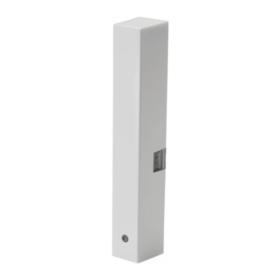
- Page 8 Function and device overview Electronic unit Screw holes Battery compartment Infra-red sensor (reflection coupler) Tamper contact Device LED and teach-in button...
-
Page 9: Start-Up
Start-up Start-up 5.1 Mounting Please read this entire section before starting to carry out the mounting procedure. Do not yet place the cap! 5.1.1 Selecting a suitable mounting location • Select a door or window for mounting the door/win- dow sensor. •... - Page 10 Start-up If the door/window casement is too small the de- vice can not be mounted. For poorly reflecting surfaces (e.g. dark door/ window frames) the supplied reflecting sticker has to be fixed to the door/window casement on the opposite of the infra-red sensor. 5.1.2 Adhesive stripe or screw mounting You can fix the door/window sensor by the supplied •...
- Page 11 Start-up Adhesive stripe mounting For mounting the door/window sensor by the adhesive stripe, please proceed as follows: • Attach the double-sided adhesive stripe to the back of the electronic unit (B) and press the electronic unit onto the desired position of the window frame. Make sure that the mounting surface is smooth, solid, non-disturbed, free of dust, grease and solvents and not too cold to ensure long-time...
- Page 12 Start-up earbeitet2.pdf 1 28.03.2014 10:43:37 For mounting the door/window sensor by screws, please proceed as follows: • Use a pen to mark the bore holes (C) on the door/ window frame. • If you are working with hard surfaces you should pre-drill the holes marked using a 1.5 mm drill (not necessary for soft surfaces).
-
Page 13: Inserting And Replacing Battery
Start-up 5.2 Inserting and replacing battery Please read this entire section before inserting or replacing the battery. Please pay attention to the flashing signals of the device LED while inserting the battery (see „6.4 Error messages and information indicated by the device LED“ on page 53). 5.3 Inserting battery •... - Page 14 Start-up • Place the supplied 1.5 V LR03/micro/AAA battery into the battery compartment (D), using the polarity markings to ensure the polarity is correct. • Please pay attention to the flashing signals of the device LED while inserting the battery (see „5.3.2 Response once the battery has been inserted“...
- Page 15 Start-up Used batteries should not be disposed of with regular domestic waste! Instead, take them to your local battery disposal point. If the device being controlled does not respond when a signal is sent or if the flashing code indicating an empty battery appears (5x red flashes), follow the instructions of the previous section to replace the old battery with one new of type LR03/micro/AAA.
-
Page 16: Teaching-In
5.4.1 Teaching-in directly in to HomeMatic devices If you would like to teach-in the door/window sensor to one or more HomeMatic devices, you must put the de- vices to be linked into teach-in mode and select the re- quired teach-in channel. To do this, proceed as follows: During teach-in, please make sure you maintain a distance of at least 50 cm between the devices. - Page 17 Start-up • Now put the device in to which you wish to teach-in the door/window sensor into teach-in mode. Please follow the relevant operating manual instructions of the corresponding device. The device LED lights up green to indicate that teach- ing-in has been successful.
- Page 18 HomeMatic software "WebUI". Therefore, your door/window sensor has to be taught-in to the HomeMatic Central Control Unit first. New devices are taught-in to the central control unit via the HomeMatic „WebUI“. A soon as a component has been taught-in to a central control unit, it can only be connected to other components via this unit.
- Page 19 Start-up • To activate teach-in mode, click "Start teach-in mode". • Teach-in mode remains activated for 60 seconds. An information box shows how much teach-in time remains. • Meanwhile, activate the teach-in mode of the door/ window sensor to teach-in as well. Press the teach- in button (G) briefly using a pointed object.
-
Page 20: Configuring Newly Taught-In Devices
5.5 Configuring newly taught-in devices Once you have taught-in your door/window sensor to the HomeMatic Central Control Unit, it will be moved to the inbox. Here, you must configure the device and its associated channels in order to make them available... -
Page 21: Errors And Information Indicated By The Device Led
Please refer to the HomeMatic WebUI Manual for more details (you can find this in the „Downloads“ area of the web- site www.homematic.com). -
Page 22: Command Not Confirmed
1% of an hour (i.e. 36 seconds in an hour). Devices must cease transmission when they reach the 1% limit until this time restriction comes to an end. HomeMatic devices are designed and produced with 100% conformity to this regulation. -
Page 23: Error Messages And Information Indicated By The Device Led
Errors and information indicated by the device LED During normal operation, the duty cycle is not usually reached. However, repeated and wireless-intensive teach-in processes mean that it may be reached in isolated instances during start-up or initial installation of a system. If the duty cycle is exceeded, this is indi- cated by one long and one short red flash of the device LED, and may manifest itself in the device temporarily working incorrectly. - Page 24 Errors and information indicated by the device LED Teach-in Flashing code Meaning Sensor in teach-in mode Slow orange flashing (waiting for teach-in partner or parameterisation) Fast orange flashing Teaching-in active Long green lighting Teach-in successful Long red lighting Teach-in failed Error messages Flashing code Meaning...
-
Page 25: Restore Factory Settings
Restore factory settings Restore factory settings Flashing code Meaning Slow red flashing Stage before resetting to factory settings (device is waiting for teach-in button to be pressed and held in order to carry out a reset, or for a short button press to cancel the process) Fast red flashing Sensor is being reset to the... - Page 26 Restore factory settings > 5 s If you want to cancel the reset procedure at this point, you can either press the teach-in button again briefly or wait for 15 seconds. In both cas- es, the slow red flashing will stop. •...
-
Page 27: Maintenance And Cleaning
WebUI user interface. Please refer to the WebUI Manual for further information (you can find this in the Downloads area of the website www.homematic.com). Maintenance and cleaning This product does not require you to carry out any main- tenance other than replacing the battery when neces- sary. -
Page 28: General Information About Radio Operation
Entwicklung GmbH hereby declares that this de- vice complies with the essential requirements and other relevant regulations of Directive 1999/5/EC. You can find the full declaration of conformity at www.homematic.com. -
Page 29: Technical Specifications
Technical specifications 10 Technical specifications Device short name: HM-Sec-SCo Supply voltage: 1x 1.5 V LR03/micro/AAA Current consumption: 100 mA (max.) Battery life: 2 years (typ.) Degree of protection: IP20 Ambient temperature: -20 to +55 °C Radio frequency: 868.3 MHz Receiver category: SRD category 2 Typ. - Page 30 eQ-3 Entwicklung GmbH Maiburger Straße 36 D-26789 Leer www.eQ-3.de...
Need help?
Do you have a question about the HM-Sec-SCo and is the answer not in the manual?
Questions and answers