
Related Manuals for Fondital gazelle techno classic


Summary of Contents for Fondital gazelle techno classic
- Page 1 G 009 - 04 G a s r a d i a t o r s CLASSIC TECHNICAL DATA AND INSTRUCTIONS CE 0051...
-
Page 2: Important
To the customer Thank you for choosing one of our gas radiators. Please read these instructions carefully. This handbook contains instructions for the fitter and user on how to install, use and service these appliances. IMPORTANT • Gas appliances must be installed by an approved company in compliance with current legislation;... -
Page 3: General Notes For The User And Installer
GENERAL NOTES FOR THE USER AND INSTALLER This instruction handbook is an requirements and following the If the radiator is not used for a integral and essential part of the manufacturer’s instructions. certain length of time, switch off supply. A professionally qualified person the electricity and gas supply. -
Page 4: Table Of Contents
CONTENTS Important _____________________________________________________________________ page 2 General notes for the user and installer ____________________________________________ page 3 1. Instructions for the user _____________________________________________________ page 5 1.1 Control panel and settings _____________________________________________________ page 5 1.2 Humidifier __________________________________________________________________ page 6 1.3 How to operate the radiator ____________________________________________________ page 6 1.3.1 Switching on ___________________________________________________________ page 6... -
Page 5: Instructions For The User
1. INSTRUCTIONS FOR THE USER WARNING Always ensure to have first ingnition performed by professional personnel only A on/off main switch B timer clock C temperature regulator D power on light (green) E burner minimum power light (green) F burner maximum power light (green) G emergency shutdown light (red) H overheating shutdown light (red) L reset button... -
Page 6: Humidifier
1.2 HUMIDIFIER Important: fter a long period of inactivity, 1.3.3 Regulating the temperature particularly with LPG models, the radiator On the left-hand side of the boiler there may be difficult to start up due to air in This radiator comes with a temperature is a pull-out plastic container used as a the pipes. -
Page 7: Timer Clock
1.3.4 Timer clock Move the red segments (pins) towards • If the room is used by unsupervised the outside of the dial to the periods you children or anyone who is disabled, it is The clock on the timer is used to wish the radiator to come on. -
Page 8: Technical Features And Dimensions
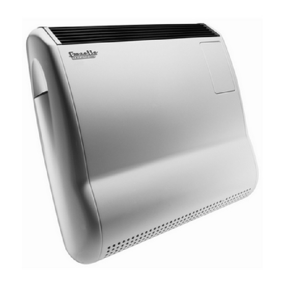
Main features of the GAZELLE TECHNO on 5000 and 7000 models) CLASSIC radiator: - Ambient temperature probe The GAZELLE TECHNO CLASSIC is - Temperature probe on exchanger body an individual gas radiator with a room- - High-efficiency finned heat exchanger... -
Page 9: Instructions For The Installer
3. INSTRUCTIONS FOR THE INSTALLER This part of the manual contains Use the specific hexagonal spanner installation instructions for gas radiators. provided (see the picture below). It is for use by qualified fitters, the only persons authorised to install gas radiators professionally as prescribed by the current regulations. -
Page 10: Straight Wall Flue System
3.2.2 Flue system with extensions or In order to extend the air intake / flue elbows gas pipes, the Manufacturer can supply a split-pipe adaptor KIT fitted with a The air intake and outlet pipes of Gazelle supporting bracket. Techno Classic radiators can be fitted Alternatively, air intake / flue gas pipes with extensions and elbows. - Page 11 • To join an elbow to a pipe or two pipes Rear section together, insert one in the other and then fit on the gasket H (fig. 14 B). • When the load loss of the pipes is low (see notes to table 2, sub-section 3.2.4), place at the air intake opening the 25-mm air diaphragm R (figs.
-
Page 12: Roof Flue System
"Total Maximum Load Loss”. used (35 or 60 mm). outlet points. table 2 GAZELLE TECHNO CLASSIC 3000 5000 Maximum load loss Outside diameter of the pipe Starting 90° elbow for twin pipe adaptor 0.75... -
Page 13: Connecting To The Gas Supply
Sample calculation (fig. 19): GAZELLE TECHNO CLASSIC 5000 • Split pipe system • Direct air-intake behind the radiator • Flue gas outlet on the roof, height 6 m The table shows that the maximum load loss is: 12 Pa Air intake: Pipe diameter 35 mm length 30 cm = 2 x 0.30 = 0.6 Pa... -
Page 14: Connecting To The Mains
16: TANGENTIAL FAN THERMOSTAT : violet fig. 21 The electrical connections are made The Gazelle Techno Classic gas radiator To control more than one radiator using by means of a terminal block on the allows the following applications: a single timer-thermostat:... -
Page 15: Changing Type Of Gas
fig. 23 3.5 CHANGING TYPE OF GAS Gas radiators are factory calibrated and - To adjust minimum pressure, undo sealed according to the type of gas • LPG the screw and insert the measuring instrument in pressure check point A. available and the countries to which they Undo the cover of pressure regulator are exported. -
Page 16: Troubleshooting
4. TROUBLESHOOTING PROBLEM POSSIBLE CAUSES SOLUTIONS Check that the gas cock is on No gas is being supplied Check gas flow to the valve Air in the gas pipe Repeat the ignition sequence a few times Check that the grilles in the casing are free from obstruction such as cloths, and Intervention of the safety thermostat due to make sure air circulation in the room is not... -
Page 17: Technical Data
Max NOx value mg/kWh 173.8 79.8 126.3 NOx emission class Noise level at maximum fan speed Noise level at minimum fan speed GAZELLE TECHNO CLASSIC 3000 G20 Nat. gas G30 butane G31 propane Main burner injector mm/100 Gas supply pressure mbar... -
Page 18: Manufacturer's Declaration Of Conformity
GAZELLE TECHNO CLASSIC 7000 G31 propane G20 Nat. gas G30 butane Main burner injector mm/100 Gas supply pressure mbar Maximum gas pressure at the injector mbar Minimum gas pressure at the injector mbar 16.8 ∆P (at maximum output) 58 - 62... - Page 19 6. DECLARATION OF CONFORMITY...
-
Page 20: Installation Sequence For Flue Gas Discharge From The Wall
INSTALLATION SEqUENCE FOR FLUE GAS DISCHARGE FROM THE WALL... - Page 21 Follow the installation instructions below: 1. Remove the appliance from its packaging, starting with the air intake and flue gas pipes and the terminal. 2. Apply the paper template provided to the exact position on the wall where you wish to install the appliance. ALTO - ALTO ALTO - EN HAUT BOVEN - BOVEN...
- Page 22 4. Measure the depth of the air intake and flue gas holes made in the wall and cut the pipes 5 cm longer than this depth.
- Page 23 5. Fit the supplied seals to the air intake and flue gas pipes. 6. Using a lubricant compound if necessary, push the two pipes into the machine.
- Page 24 7. While holding the machine, insert the air intake /flue gas pipes through the hole in the wall and fix the machine to the wall using the screws provided. How to take the casing off: 8. CLASSIC VERSION ONLY In installations with Standard pipes IT IS MANDATORY TO INSTALL on the terminal section of the air-intake pipe THE AIR DIAPHRAGM PROVIDED, in order for the appliance to operate correctly.
- Page 25 9. Fix the ring plate to the outlet terminal, inserting the screws in the wall according to one of the two possible solution described below. For safety reasons always fix the flue gas pipe flange. SOLUTION A Fix the ring-plate and terminal into place at the same time using F wall-plugs provided.
- Page 26 11. Screw in the gas pipe using two spanners in order to prevent the joint from twisting. 12. Electrically connect the earth lead to the green connector (use the fast-on provided in the installation kit) (fig. 1). See fig. 2 for instructions on how to connect several appliances to a single room thermostat.
- Page 28 25079 VOBARNO (Brescia) Italy - Via Cerreto, 40 Tel. +39 0365 878.31 - Fax +39 0365 878.576 e mail: info@fondital.it - www.fondital.com The Manufacture reserves the right to make minor modifications to the products as required, without affecting the basic features.
Need help?
Do you have a question about the gazelle techno classic and is the answer not in the manual?
Questions and answers