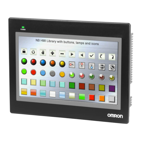
Omron NB Series Service Manual

Omron NB Series Service Manual

Programmable terminal
Hide thumbs Also See for NB Series:

Advertisement

Quick Links

Programmable Termi nal NB-s eries
Replace Guide
From NB to NB-V1
□□
NB3Q-TW
B-V1
□□
NB5Q-TW
B-V1
□□
NB7W-TW
B-V1
NB10W-TW01B-V1
V468-E1-01

Advertisement

Table of Contents
loading

Summary of Contents for Omron NB Series

  • Page 1 Programmable Termi nal NB-s eries Replace Guide From NB to NB-V1 □□ NB3Q-TW B-V1 □□ NB5Q-TW B-V1 □□ NB7W-TW B-V1 NB10W-TW01B-V1 V468-E1-01...
  • Page 3 ■ Introduction This document provides information useful to replace NB Programmable Terminal with its successor model NB-V1 but does not contain safety precautions. Please prepare user’s manuals for NB-series Programmable Terminal and read and understand safety precautions and necessary information before using the product.
  • Page 4: Terms And Conditions Agreement

    Omron’s exclusive warranty is that the Products will be free from defects in materials and workmanship for a period of twelve months from the date of sale by Omron (or such other period expressed in writing by Omron). Omron disclaims all other warranties, express or implied.
  • Page 5: Disclaimers

    Disclaimers Performance Data Data presented in Omron Company websites, catalogs and other materials is provided as a guide for the user in determining suitability and does not constitute a warranty. It may represent the result of Omron’s test conditions, and the user must correlate it to actual application requirements. Actual performance is subject to the Omron’s Warranty and Limitations of Liability.
  • Page 6: Table Of Contents

    CONTENTS ............4 ERMS AND ONDITIONS GREEMENT Warranty, Limitations of Liability ................4 Application Considerations ..................4 Disclaimers ......................5 CONTENTS ..................... 6 ................7 1 ELATED ANUALS ..................8 2 RECAUTIONS 2-1 Test Function ....................8 ..........9 3 PPLICABLE MODELS AND SPECIFICATIONS 3-1...
  • Page 7: 1 Related Manuals

    1 Related Manuals The following manuals are related. Use these manuals for reference. Cat. No. Models Manual name V106 NB3Q-TW□□B(-V1) NB-series Programmable Terminals NB5Q-TW□□B(-V1) NB-Designer NB7W-TW□□B(-V1) Operation Manual NB10W-TW01B(-V1) V107 NB3Q-TW□□B(-V1) NB-series Programmable Terminals NB5Q-TW□□B(-V1) Setup Manual NB7W-TW□□B(-V1) NB10W-TW01B(-V1) V108 NB3Q-TW□□B(-V1) NB-series Programmable Terminals NB5Q-TW□□B(-V1)
  • Page 8: 2 Precautions

    2 Precautions 2-1 Test Function The Test Function is performed on PC, and it has different behaviors with actual NB running system. A problem may occur due to communication timing, cable differences and unexpected PC circumstances (such as freeze). When the Test Function is performed, please consider possible unexpected circumstances on the actual NB running system and confirm that any dangerous event will not occur beforehand.
  • Page 9: 3 Applicable Models And Specifications

    3 Applicable models and specifications 3-1 Applicable models Discontinued Products Recommended Replacements Programmable Terminal Programmable Terminal NB3Q-TW00B NB3Q-TW00B-V1 NB3Q-TW01B NB3Q-TW01B-V1 NB5Q-TW00B NB5Q-TW00B-V1 NB5Q-TW01B NB5Q-TW01B-V1 NB7W-TW00B NB7W-TW00B-V1 NB7W-TW01B NB7W-TW01B-V1 NB10W-TW01B NB10W-TW01B-V1...
  • Page 10: Specifications

    3-2 Specifications ■ Body Color Product models to be discontinued Recommended replacement models NB□□-TW□□B NB□□-TW□□B-V1 Black Black ■ Terminals/ Wire connection Product models to be discontinued Recommended replacement models NB□□-TW□□B NB□□-TW□□B-V1...
  • Page 11 Product models to be discontinued Recommended replacement models NB□□-TW□□B NB□□-TW□□B-V1...
  • Page 12 ■Mounting dimensions Discontinued Products Recommended Replacements NB□□-TW□□B NB□□-TW□□B NB3Q-TW□□B NB3Q-TW□□B -V1 Panel cutout Panel cutout 119.0(+0.5/-0) (W), 93.0(+0.5/-0) (H) 119.0(+0.5/-0) (W), 93.0(+0.5/-0) (H) Panel thickness: 1.6 to 4.8mm Panel thickness: 1.6 to 4.8mm NB5Q-TW□□B NB5Q-TW□□B -V1 Panel cutout Panel cutout 172.4(+0.5/-0) (W), 131.0(+0.5/-0) (H) 172.4(+0.5/-0) (W), 131.0(+0.5/-0) (H) Panel thickness: 1.6 to 4.8mm...
  • Page 13 ■ Characteristics Discontinued Products Recommended Replacements NB□□-TW□□B NB□□-TW□□B Item NB3Q NB5Q NB7W NB10W NB3Q-V1 NB5Q-V1 NB7W-V1 NB10W-V1 Display TFT LCD TFT LCD device QVGA QVGA QVGA QVGA WVGA WSVGA Resolution WVGA 800×480 320×240 320×234 320×240 320×240 800×480 1024×600 65536 colors 65536 colors Color Support...
  • Page 14: 4 Workflow

    4 Workflow 4-1 Workflow The replacement procedure with NB-V1 is as follows. Operations in are explained from the next page. 4-2 Preparation 4-2-1 Confirmation of replaceability 4-2-2 Uploading the project from the existing NB 4-2-3 Converting the project for NB-V1 4 -3 Removing the currently installed NB 4-3-1 Turning OFF the power to the currently installed NB 4-3-2 Removing all cables...
  • Page 15: Preparation

    4-2 Preparation 4-2-1 Confirmation of replaceability Refer to NB-series Programmable Terminals Host Connection Manual (V108-E1) if the current used PLC is supported by the NB-V1. 4-2-2 Uploading the project from the existing NB Start the NB-Designer. *NB-Designer Ver.1.60 or higher must be installed in the computer.
  • Page 16 3. Select Set button, choose Communication Method and press OK button. 4. Press Upload Project File. Select Project Data , Logo File and Recipe File as needed. 5. Input the project name, and specify save destination then select the Save Button.
  • Page 17 6. Input password for upload, then press OK button. The file is saved in the specified folder. 7. Select Import Project from the HMI Menu. 8. Select the upload .pkg file, press Open button.
  • Page 18 9. Input password, press OK button. The file is open. Go to 4-2-3 Converting the project for NB-V1.
  • Page 19 4-2-3 Converting the project for NB-V1 1. While the NB-Designer is in offline state and the uploaded project is opened, right-Select the HMI Icon and select Change PT model from the menu. * *NB5Q and NB10W have different resolutions. Please check the screen.
  • Page 20 2. Select NB-V1 device model, and then Select the OK Button. *The NB-V1 project data cannot be converted to NB project. 3. The warning message is displayed. Select Button. *This message is displayed when the device is changed. 4. The warning message is displayed.
  • Page 21 5. Select Recomple from Tools menu. 6. Select Save As from the File Menu. 7. Input the project name, and then Select the OK Button.
  • Page 22 8. Select Export Project from the File Menu. 9. Specify export destination, input the file name, and then Select the OK Button. The project file is saved in the specified folder. 10. Go to 4-3 Removing the currently installed NB.
  • Page 23: Removing The Currently Installed Nb

    4-3 Removing the currently installed NB 4-3-1 Turning OFF the power to the currently installed NB Turn OFF the 24V DC power supply to the NB. 4-3-2 Removing all cables Remove all the cables connected to the NB. 4-3-3 Removing the storage devices (if used) Remove the USB memory.
  • Page 24: Installing Nb-V1

    4-4 Installing NB-V1 4-4-1 Installing the NB-V1 to the operation panel Mount the NB-V1 to the operation panel using panel mounting brackets and a screwdriver. 4-4-2 Wiring the cables Connect all the cables for the NB-V1. 4-4-3 Installing the storage devices (If necessary) Install the USB memory.
  • Page 25: Start-Up

    4-5 Start-up 4-5-1 Turning ON the power to the NB-V1 Turn ON the 24V DC power supply to the NB-V1. 4-5-2 Downloading the project to the NB-V1 If you download the project with a USB cable, you need to install the driver. For details on how to install the USB driver, refer to "2-4 Installation of USB driver for NB"...
  • Page 26 3. Select the Yes Button. The data is downloaded, and the HMI restarts. 4-5-3 Checking the settings and communications Run the project on the actual system and check that correct values are written to the connected device, the pages change correctly, and values set at the connected device are updated. 4-5-4 Starting operation Start actual operation.
  • Page 27: Appendix-1 Transferring Project Data By Using A Media Device

    Appendix-1 Transferring project data by using a media device Even if NB-Designer is not available, project files can be transferred by using a media device. **NB-Designer is required for screen conversion. 4-2-2 Uploading the project from the existing NB -> Go to A-1-1 4-5-2 Downloading the project to the NB-V1 ->...
  • Page 28 4. Specify the destination media and file name and touch the OK Button. The project is uploaded to the specified media. 5. Input password. The upload password is required during the export. If the upload password is not set, it needs to use the default password of 888888.
  • Page 29 7. Specify the destination media and file name and touch the OK Button. The recipe is uploaded to the specified media. 8. Remove the media from the 9. Insert the media device to which the project was uploaded to the computer and start the Designer .
  • Page 30 11. Open the destination media and select the project file you upload from NB and touch the Open Button. 12. Input password, press OK. 13. The warning message is displayed. Select the OK Button.
  • Page 31 14. Right-Select the HMI Icon and select Change PT model from the menu. 15. Select NB-V1 device model, and then Select the OK Button. 16. The warning message is displayed. Select the Yes Button. *This message is displayed when the device is changed.
  • Page 32 17. The warning message is displayed. Select the OK Button. *This message is displayed when the device version is updated. 18. Select Recomple from Tools menu. 19. Compiled Successfully.
  • Page 33 20. Select Save As from File menu. 21. Specify the destination media and file name and touch the OK Button. 22. Select Export Project from the File Menu.
  • Page 34 23. Specify the destination media and file name and touch the OK Button. 24. The file is successfully exported. Touch the OK Button. A-1-2 Downloading by using a storage media 1. Insert the storage media into the HMI for the download into the HMI.
  • Page 35 2. Enter the System Setting Mode following the procedures below. (1) Set both the DIP switches SW1 and SW2 on the back side to ON. (2) Press the Reset switch, restart the NB Unit, and then it enters into the System Setting Mode.
  • Page 36 6. Select the .rcp file to download and touch the OK Button. The selected file is downloaded to the HMI.
  • Page 37: Revision History

    Revision History Revision Date Revised content History February 2023 Original production...
  • Page 38 Tel: (1) 847-843-7900 Fax: (1) 847-843-7787 ©OMRON Corporation 2022 2023 All Rights Reserved. OMRON ASIA PACIFIC PTE. LTD. OMRON (CHINA) CO., LTD. In the interest of product improvement, 438B Alexandra Road, #08-01/02 Alexandra Room 2211, Bank of China Tower, specifications are subject to change without notice.

Table of Contents