Omron NB3Q-TW00B Startup Manual Manual
Nb-series
programmable terminals
Hide thumbs
Also See for NB3Q-TW00B:
- Operation manual (548 pages) ,
- Setup manual (102 pages) ,
- Service manual (38 pages)

Related Manuals for Omron NB3Q-TW00B


Summary of Contents for Omron NB3Q-TW00B
- Page 1 Industrial automation Elincom Group European Union: www.elinco.eu Russia: www.elinc.ru STARTUP GUIDE MANUAL...
- Page 2 OMRON. No patent liability is assumed with respect to the use of the information contained herein. Moreover, because OMRON is constantly striving to improve its high-quality products, the information contained in this manual is subject to change without notice.
- Page 3 NB-series NB3Q-TW NB5Q-TW NB7W-TW NB10W-TW01B Programmable Terminals Startup Guide Manual Revised February 2014...
-
Page 5: Introduction
OMRON representative. • Make sure that the ratings and performance characteristics of the product are sufficient for the systems, machines, and equipment, and be sure to provide the systems, machines, and equipment with double safety mechanisms. -
Page 6: Nb-Series Manuals
NB-series Manuals NB-series manuals are organized in the sections listed in the following tables. Refer to the appropriate section in the manuals as required. Programmable Terminals Startup Guide Manual (Cat. No. V109) (This manual) Section Contents Section 1 NB Overview This section provide specifications of the NB Unit, describes its names and functions of the various parts. - Page 7 Programmable Terminals Setup Manual (Cat. No. V107) Section Contents Section 1 Part Names and Functions This section describes the names and functions of the various parts of an NB Unit. Section 2 Installing the NB Unit and This section describes the methods used to install the NB Unit and Connecting Peripheral Devices connect peripheral devices.
-
Page 8: Manual Structure
Page tab procedure. Height Gives the number Opening dimensions of the section. Models Opening Dimension (W H mm) NB3Q-TW00B/TW01B 119.0(+0.5/-0) 93.0(+0.5/-0) NB5Q-TW00B/TW01B 172.4(+0.5/-0) 131.0(+0.5/-0) NB7W-TW00B/TW01B 191.0(+0.5/-0) 137.0(+0.5/-0) NB10W-TW01B 258.0(+0.5/-0) 200.0(+0.5/-0) As follows, insert panel fixators at the locations indicated by red box around the back of the NB Unit. -
Page 9: Terminology
Indicates a Serial Communication Board for an OMRON SYSMAC CS/CJ-Series PLC. Board Communication Board Indicates a Communication Board for an OMRON C200HX/HG/HE(-Z) PLC. CPU Unit Indicates a CPU Unit in the OMRON CP, CS/CJ or SYSMAC C Series of Programmable Controllers. NB-Designer Indicates the OMRON NB-Designer. Host Indicates the PLC and other units functioning as the control devices for NB-Series Units. - Page 10 NB-series Programmable Terminals Startup Guide Manual(V109)
-
Page 11: Table Of Contents
CONTENTS Introduction....................... 1 NB-series Manuals....................2 Manual Structure ...................... 4 Terminology ......................5 Terms and Conditions Agreement ................9 Safety Precautions ....................11 Precautions for Safe Use ..................14 Precautions for Correct Use .................. 16 Conformance to EC Directives ................17 Related Manuals ..................... - Page 12 6-3-2 Communication-related Troubles ....................6-25 6-3-3 Hardware Troubles ........................6-29 6-3-4 Errors occurred when the UDP communications with OMRON PLC ........6-31 6-3-5 Other Troubles........................... 6-31 Unit Replacement Precautions..................... 6-33 Revision History ......................1 NB-series Programmable Terminals Startup Guide Manual(V109)
-
Page 13: Terms And Conditions Agreement
Omron’s exclusive warranty is that the Products will be free from defects in materials and workman- ship for a period of twelve months from the date of sale by Omron (or such other period expressed in writing by Omron). Omron disclaims all other warranties, express or implied. - Page 14 Disclaimers Performance Data Data presented in Omron Company websites, catalogs and other materials is provided as a guide for the user in determining suitability and does not constitute a warranty. It may represent the result of Omron's test conditions, and the user must correlate it to actual application requirements. Actual performance is subject to the Omron's Warranty and Limitations of Liability.
-
Page 15: Safety Precautions
Safety Precautions Notation Used for Safety Information The following notation is used in this manual to provide precautions required to ensure safe usage of the product. The safety precautions that are provided are extremely important to safety. Always read and heed the information provided in all safety precautions. Indicates an imminently hazardous situation which, WARNING if not avoided, will result in death or serious injury. - Page 16 WARNING Do not attempt to take the product apart and do not touch the product inside while the power is being supplied. Otherwise it may result in electric shock. Always ensure that the personnel in charge confirm that installation, inspection, and maintenance were properly performed for the NB Unit.
- Page 17 Precaution WARNING Wiring In the case of the NB Series, when grounding the positive terminal of power supply of 24 V to the NB, do not ground functional grounding terminal at NB side. Some functions of a PC connected to the NB may cause a short circuit and the NB Unit may cause damage. •...
-
Page 18: Precautions For Safe Use
Precautions for Safe Use • When unpacking the NB Units and the peripheral devices, check carefully for any external scratches or other damages. Also, shake the Units gently and check for any abnormal sound. • The NB Unit must be installed in a control panel. •... - Page 19 • When changing the password with the screen, do not reset or turn OFF the power supply until writing is finished. Failure to save the password may cause the screen to fail to function. • When using an equipment monitor, confirm the safety of the system before carrying out the following operations: •...
-
Page 20: Precautions For Correct Use
Precautions for Correct Use • Do not install the unit in any of the following locations: Locations subject to severe changes in temperature Locations subject to temperatures or humidity outside the range specified in the specifications Locations subject to condensation as the result of high humidity Locations subject to corrosive or flammable gases Locations subject to strong shock or vibration Locations outdoors subject to direct wind and rain... -
Page 21: Conformance To Ec Directives
OMRON products are electronic devices that are incorporated in machines and manufacturing installations. OMRON PTs conform to the related EMC Directives (see note) so that the devices and machines into which they are built can more easily conform to EMC Directives. The actual products have been through inspections and are completely in accordance with EMC directives. -
Page 22: Related Manuals
Related Manuals The related manuals are as follows: Devices and Software Manual Name Manual No. NB series NB Series NB-Designer Operation Manual V106 NB Series Setup Manual V107 NB Series Host Connection Manual V108 NB Series Startup Guide (This manual) V109 SYSMAC CP Series CP1L CPU Unit Operation Manual W462... -
Page 23: Nb Overview
NB Overview This section provide specifications of the NB Unit, describes its names and functions of the various parts. 1-1 Models of NB Series ......... . . 1-2 1-2 Part Names and Functions . -
Page 24: Models Of Nb Series
1 NB Overview Models of NB Series There are 7 models of NB series PTs available now: NB3Q-TW00B/TW01B, NB5Q-TW00B/TW01B, NB7W-TW00B/TW01B and NB10W-TW01B. With TFT display used, NB series has higher cost performance. The LED backlight used is more environmentally-friendly, energy-efficient and with longer service life compared to traditional CCFL backlight. -
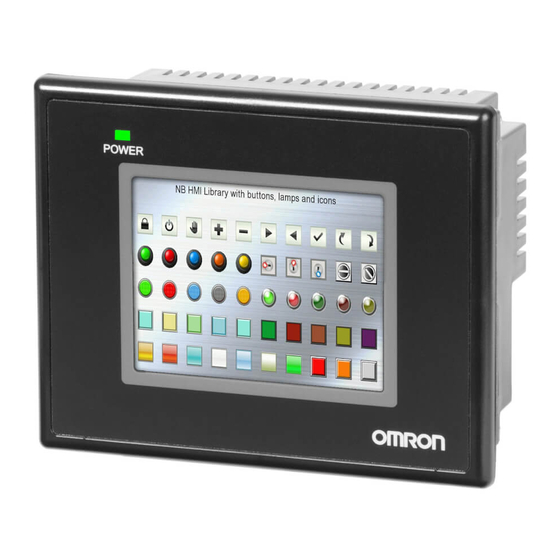
Page 25: Part Names And Functions
1 NB Overview Part Names and Functions This section describes the names and functions of each part of the NB Unit. NB3Q-TW00B/NB3Q-TW01B model Front view Power Indicator Display Back view : NB -TW01B only Precautions for Safe Use Confirm the safety of the system before turning ON or OFF the power supply, or pressing the reset button. - Page 26 1 NB Overview NB5Q-TW00B/NB5Q-TW01B model Front view Power Indicator Display Back view : NB -TW01B only Precautions for Safe Use Confirm the safety of the system before turning ON or OFF the power supply, or pressing the reset button. NB-series Programmable Terminals Startup Guide Manual(V109)
- Page 27 1 NB Overview NB7W-TW00B/NB7W-TW01B model Front view Power Indicator Display Back view : NB -TW01B only Precautions for Safe Use Confirm the safety of the system before turning ON or OFF the power supply, or pressing the reset button. NB-series Programmable Terminals Startup Guide Manual(V109)
- Page 28 1 NB Overview NB10W-TW01B model Front view Power Indicator Display Back view Precautions for Safe Use Confirm the safety of the system before turning ON or OFF the power supply, or pressing the reset button. NB-series Programmable Terminals Startup Guide Manual(V109)
- Page 29 1 NB Overview Serial Port COM1 • NB5Q/NB7W/NB10W-TW Serial port COM1 is a 9-pin D-type socket port. This port supports RS-232C communication function, making it connectable to a controller which features RS-232C function, and it can also be used for downloading programs or debugging for the product. The pins are defined as follows: Pins Signals...
- Page 30 1 NB Overview Precaution for Cable Fabrication The COM 2 ports included in this manual and marked by cable manufacturers are intended for the PT of NB5Q/NB7W/NB10W-TW B models, therefore when communication connection is carried out with the COM 1 port of NB3Q-TW B, please refer to the pin definitions in this section prior to connection.
- Page 31 1 NB Overview USB SLAVE USB SLAVE port is USB B-type port, which can connect the USB port on PC side to perform the uploading, downloading, debugging of the programs for the product and the Pictbridge printing. And its pins are defined as follows: Pins Signals Functions...
- Page 32 1 NB Overview DIP Switch NB5Q/NB7W only has 2 switches SW1 and SW2, while for the NB3Q and NB10W, there are totally 4 DIP switches, and for all models, SW1 and SW2 feature the same functions. The settings and corresponding operating modes are as follows: Operating modes System Setting Mode Calibrate Mode...
-
Page 33: System Design
System Design This section describes the manual structure, takes NB7W as an example to introduce the operation procedures of the NB system. 2-1 About this Manual ..........2-2 2-2 Demonstration System . -
Page 34: About This Manual
2 System Design About this Manual This section describes the manual structure and operation procedures of the NB7W system by way of example. Manual Structure The case of the system using the NB Series (Take NB7W as an example) is described in the follow- ing sequence in this manual: Chapter 1. -
Page 35: Demonstration System
Start Menu. Click [Sample Screen(NB7)] in the [Start]-[All Programs]-[OMRON]-[NB-Designer]-[Screen Data] to open the demonstration project. Please note that the demonstration project includes macro files, so it can only be edited by running as an administrator on operating systems other than XP. - Page 36 2 System Design • The garage door will not be closed before the CLOSE switch is pressed or the vehicle sensor is ON after being fully opened. a [Deactivate Auto-close] button • The garage door will be closed when the sensors detect that the entire vehicle is in the garage. •...
- Page 37 2 System Design System Components The following components are used in the garage door control system: Display device • NB7W-TW • XW2Z-200T(PT-PLC connecting cable: 2m) • XW2Z-500T(PT-PLC connecting cable: 5m) • CP1E-N20D - (20-dot I/O type) Programming device and software •...
- Page 38 2 System Design CP1E The CP1E is an economical PLC with high performance, which can be ideally used for small-scale manufacturing machines and control systems. The CP1E-N20D - is shown below: Please refer to the SYSMAC CP series CP1E CPU Unit User Manual for details on CP1E. NB-series Programmable Terminals Startup Guide Manual(V109)
- Page 39 2 System Design Addresses allocation table Memory allocation table Addresses Function Component Name Corresponding Screen W_bit 0.01 Automatically close Bit Button Fully Open (disabled) W_bit 0.02 Start the maintenance Bit Button Wait screen W_bit 1.00 Open Bit Button/ All Screens/Check 2 Bit Lamp W_bit 1.01 Stop...
- Page 40 2 System Design NB7W Screen The screens below will be displayed on NB7W. (1) WAIT The screen will be displayed when the garage door is fully closed. The number of flash of headlights is indicated in the form of Level Meter. The transparent button on the upper left corner is used for switching to the maintenance screen.
- Page 41 2 System Design (5) FULLY OPEN The screen will be displayed when the garage door is fully opened. There is a button for keeping the garage door open. (6) CHECK 1 This screen is used for maintenance by displaying the input states of the sensors. The screen will be displayed when the maintenance button on [1 WAIT] screen is pressed.
- Page 42 2 System Design The screen switch flow chart is shown below. Maintenance Button ON 1.Wait 6.Check 1 Waiting Screen Button ON Headlight Status ON Next Screen Last Screen Open Button ON Button ON Button ON 2.Open 7.Check 2 Stop Button ON Next Screen Last Screen Upper limit...
- Page 43 2 System Design Ladder programs The ladder program examples are shown below. Refer to the SYSMAC CP series CP1E Software Manual and SYSMAC CX-Programmer Operation Manual for details on creating ladder programs. NB-series Programmable Terminals Startup Guide Manual(V109) 2-11...
- Page 44 2 System Design 2-12 NB-series Programmable Terminals Startup Guide Manual(V109)
-
Page 45: Installation And Wiring
Installation and Wiring This section describes how to install and wire the NB Unit. 3-1 Installation ........... 3-2 3-2 Equipment Wiring . -
Page 46: Installation
3 Installation and Wiring Installation This section describes the installation environment of the NB Unit and how to mount the NB Unit to the control panel. When mounting the NB unit onto the operation panel, pay attention to the following precautions. WARNING Always ensure that the personnel in charge confirm that installation, inspection, and maintenance were properly performed for the NB Unit. - Page 47 Proceed the installation following the procedures below. Panel cutout with dimensions is shown below. Fit the NB Unit into the panel from the front side. Width Height Opening dimensions Models Opening Dimension (W H mm) NB3Q-TW00B/TW01B 119.0(+0.5/-0) 93.0(+0.5/-0) NB5Q-TW00B/TW01B 172.4(+0.5/-0) 131.0(+0.5/-0) NB7W-TW00B/TW01B 191.0(+0.5/-0) 137.0(+0.5/-0) NB10W-TW01B 258.0(+0.5/-0) 200.0(+0.5/-0)
- Page 48 3 Installation and Wiring The insert positions on the body of NB3Q-TW B/NB10W-TW01B (same fixing method as above) NB3Q -TW NB10W -TW Precautions for Safe Use • Do not let metal particles enter the Units when preparing the panel. • The mounting panel must be between 1.6 and 4.8 mm thick. Tighten the Mounting Brackets evenly to a torque of between 0.5 and 0.6 N·m to maintain water and dust resistance.
-
Page 49: Equipment Wiring
The connectable power supply specifications are as follows: figure out a suitable power supply specification so as to satisfy the requirement for power supply capacity. Models Rated Voltage Allowable Voltage Range Power NB3Q-TW00B DC24V DC20.4V to 27.6V NB3Q-TW01B NB5Q-TW00B NB5Q-TW01B... - Page 50 3 Installation and Wiring Precautions for Safe Use • Firstly, wire the twisted power line to the terminal block, then install the terminal block to the NB Units. Use power lines with AWG#12 to #26 thick, peel the coating 6.5 mm length, followed by tightening the screw with 0.3 to 0.5N torque.
- Page 51 3 Installation and Wiring CP1E Wiring This section provides a brief of grounding wiring as an example. Please refer to the SYSMAC CP series CP1E CPU Unit User Manual for details on CP1E. Power Connection and Grounding Connect power and ground wires to terminal blocks. MCCB L2/N COM 01...
- Page 52 Connect CP1E and NB7W with a PT-PLC connecting cable (XW2Z-200T). CP1E RS-232C(15m max) Note Please use OMRON PT-PLC connecting cable. Using other cables may result in failure. Precautions for Safe Use • Always keep the connector screws firmly tightened after the communication cable is connected.
-
Page 53: Screen Creation
Screen Creation This section describes how to create a demonstration project through NB-Designer. 4-1 Starting NB-Designer ......... . . 4-2 4-2 Main Window of NB-Designer . -
Page 54: Starting Nb-Designer
This section describes how to start NB-Designer. NB-Designer is a programming tool (software) for creating screens displayed on the PT of NB Series. Select [Program]-[OMRON]-[NB-Designer]-[NB-Designer] from the Windows Starting Menu to start NB- Designer. The startup can also be realized by clicking the shortcut icon on the desktop. -
Page 55: Main Window Of Nb-Designer
4 Screen Creation Main Window of NB-Designer This section describes the functions of each part of the main window of NB-Designer. (a) Title Bar Indicating the names of applications. (b) Menu Bar Classifying the functions of NB-Designer in groups. Grouping functions are indicated in the form of pull-down menu. - Page 56 4 Screen Creation (h) Project File Window The Window adopts a tree structure to show the correlations between the project-related touch panel and macro files & BMP files. Project Work Space The Window displays a tree structure to show configuration of whole the project such as the PLC, the PT, and the screens.
-
Page 57: Creating Project
4 Screen Creation Creating Project This section describes the procedures to set parameters and creat a project effectively for NB7W- TW00B by way of example. The date created through NB-Designer are regarded as “Project”. Creating New Project Project creation should be started with setting the configuration plan when using NB-Designer the first time. - Page 58 4 Screen Creation Select [OMRON CP1H/L/E] from [PLC] Project Library, drag PLC to the Configuration and Setup Window after selecting it with a single-click. Select [Serial Port] from [Connector], drag it to the Configuration and Setup Window after selecting it with a single-click.
- Page 59 4 Screen Creation Adjust the positions of PT and PLC on the Configuration and Setup Window to connect serial communication cables to COM1 of HMI and COM0 of PLC. Communication Setting Click the project name on the Project Work Space Window and the connecting diagram of PT and PLC appears.
- Page 60 4 Screen Creation To setting the PLC: In “CX-Programmer” open the project, in project workspace select [PLC Settings]. Be sure to set the communication mode of PLC [Built-in RS232C Port] to “Mode: Host Link, Baud: 115200, Format: 7,2,E”. Creating Macro This project uses Macro files to initialize the value of LW.B 10.0 to 1, thus initializing the Bit Lamp on the [Stop] screen.
- Page 61 4 Screen Creation Then a macro code edit window will appear, use single right click in the “Macro Variable Table” window, select “Add Variable”, a “Macro Variable” window will open, user can define variable parameter with it. After click “OK” there is a new variable added in the “Macro Variable Table” window, it can be used in macro program as a defined variable.
- Page 62 4 Screen Creation After create a new graphics, double click to select “CTRL_BAR001.vg” in the Project File Window, select “state0” and right single click graph below and select “Copy”. Then select “Middle.vg” graphics, and copy the graphics to be copied into it. Copy the “state1” into the graphics by the same method, and then select “Rectangle”...
- Page 63 4 Screen Creation Then make the settings in the “Shape property” dialog box to the Shape Property, as shown below: Note Please save the project after the completing the creation of vector graphics. Please create the vector graphics “Up.vg” (an upward hollow triangle) and “Down.vg” (a downward hollow triangle) referring to the above-mentioned method.
- Page 64 4 Screen Creation Create a vector graphics “Dashed.vg”: first add a light cyan rectangle into the graphics, and then make the related settings in the “Shape property” dialog box, as shown below: Create a vector graphics “BlueFrame.vg”: first add a blue hollow rectangle into the graphics, and then make the related settings in the “Shape property”...
-
Page 65: Screen Creation
4 Screen Creation Screen Creation This part describes how to create screens displayed on NB7W. [1 Wait] [1 Wait] is the first display screen in the garage door control system. The screen will be displayed with the lower limit LS ON. Configure functions below: •... - Page 66 4 Screen Creation User should use this method to create total 8 screens for this project, the screen No. and names are listed as below: Screen No Screen Name Wait Open Close Stop Fully Open Check1 Check2 Check3 Double-click “Wait” Screen to open [Screen Property], select “Background Color” and set “Background Color”...
- Page 67 4 Screen Creation NB-series Programmable Terminals Startup Guide Manual(V109) 4-15...
- Page 68 4 Screen Creation Bit Button component for Open/Stop/Close Function: After the component is pressed, the bits set as write address is set to ON, and then is reset. The write addresses for each component is shown in the table below. The property settings are: Component Name Open...
- Page 69 4 Screen Creation The attribute settings are: Read Address Bar Type Standard Display Direction Left Bar Shape Rectangle Frame Color Blue Pattern Color Light grey Normal Color Light cyan Alarm Under Min Color Light cyan Min. / Max. Value Alarm Under Value [2 Open] The [2 Open] screen will be displayed when the motor for garage door opening control is activated.
- Page 70 4 Screen Creation The whole screen is shown below. The creating method is the same as that of [1 Wait]. a Screen b Fixed Text c Bit Button components [3 Close] The [3 Close] screen will be displayed when the motor for garage door closing control is activated. Configure functions below: •...
- Page 71 4 Screen Creation The whole screen is shown below. a Screen b Bit Lamp c Bit Button components The configuration of the Bit Lamp is shown below. The creating method of the Bit Button components is the same as that of [1 Wait]. Bit Lamp The Bit Lamp and a macro program are used in this project to flash the prompt information.
- Page 72 4 Screen Creation Setting the value of the LW.B 10.0 to1, the Bit Lamp can be flashed. The value of LW.B 10.0 can be initialized by the macro below. (Refer to 4-3 Creating Project for the procedure to create macro file.) The project allows the initialization by the macro after the project downloading to PT.
- Page 73 4 Screen Creation [5 Fully Open] The [5 Fully Open] screen will be displayed when the lower limit LS is ON. Configure functions below: • Fixed text indicating the garage door state. • Bit Button components to block the inputs from vehicle sensors to prevent the garage door from closing automatically.
- Page 74 4 Screen Creation The whole screen is shown below. The creating methods for fixed text and Bit Button components for [Open], [Stop] and [Close] garage door operations are the same as that of [1 Wait]. a Screen b Fixed Texts c Bit Lamp d Function Keys e Bit Button components Bit Lamp Components The states of the vehicle sensor, light sensor, upper LS and lower LS are shown by the lamp.
- Page 75 4 Screen Creation The whole screen is shown below. The creating methods for fixed text and Bit Button components for [Open], [Stop] and [Close] garage door operations are the same as that of [1 Wait]. a Screen b Fixed Texts c Bit Lamp d Function Keys e Bit Button components Bit Lamp Components The states of the [OPEN], [STOP] and [CLOSE] switches are shown by the lamp.
- Page 76 4 Screen Creation The whole screen is shown below. The creating methods for fixed text and Bit Button components for [Open], [Stop] and [Close] garage door operations are the same as that of [1 Wait]. a Screen b Fixed Texts c Number Display components d Function Keys e Bit Button components Number Display Components The current values of TIM0 and CNT0 on the ladder program.
- Page 77 4 Screen Creation PLC Control Setting In this project, the screen is controlled by PLC, to realize this function, the PLC Control component should be used. Using of PLC Control component allows to change screen from the PLC or to write a number of Current Base Screen to the PLC .
- Page 78 4 Screen Creation After click [OK], there is a new event added in the list. Write Data to PLC (Current Base Screen) Add a control event which outputs the number of Current Base Screen from the PT to the PLC in the same procedure.
-
Page 79: Pt Property
4 Screen Creation PT Property Select “Task Bar” page on “PT Property” window and in this project example, the “Display Task Bar” is not checked. Click OK button to save the settings. Select “PT Extended Property” page in “PT Property” window and in this project example, the “Use Macro when loading project”... -
Page 80: Save And Load Project
4 Screen Creation Save and Load Project This part describes how to save and open data created. It also provides a brief for test function of creating screen. Save Project Select [File]-[Save As] from the main menu. The [Project Save Path] dialogue border will pop up. Designate [Save File] location and input the file name. - Page 81 4 Screen Creation Open Projects Select [File]-[Open] from the main menu. The [Open] dialogue border will pop up. Designate the [Look in] location and select the file name. Single-click [Open]. Open the NB- Designer project file. NB-series Programmable Terminals Startup Guide Manual(V109) 4-29...
- Page 82 4 Screen Creation Test function The display effect of the created screen can be checked by the NB-Designer itself through the offline test without need to connect it to the PLC. Select [Tools] - [Compile] from the main menu. After the successful compilation, select [Tools] - [Offline Test] and then right-click the mouse to select “close”...
-
Page 83: Run
This section describes how to start running at the Host side and transfer screen data to NB7W. 5-1 Preparations ..........5-2 5-2 Run NB7W . -
Page 84: Preparations
5 Run Preparations This part describes how to start running at the Host side (CP1E) and tranfer screen data to NB7W. Connect CP1E and PC Use a USB cable to connect CP1E and a PC. a. PC b. USB Cable c. - Page 85 5 Run Select [PLC] - [Transfer] - [To PLC] from the main menu. Send data according to the procedures described on the screen. Select [PLC]-[Operating Mode]-[Run] from the main menu. CP1E starts running. Connect NB7W and PC Using a USB cable to connect NB7W and a PC The screen programs created by NB-Designer can be sent to NB7W.
- Page 86 5 Run Note USB driver for NB Series must be installed in the PC if USB is used to connect NB7W and the PC. The USB driver should be installed automatically when NB-Designer is run on a PC the first time. Refer to the NB Series NB-Designer Operation Manual (V106) for the details of USB driver installation.
-
Page 87: Run Nb7W
5 Run Run NB7W This part describes how to send screen programs of NB-Designer to NB7W . Connect NB7W and a PC. Start NB-Designer and open the screen program created. Select [Tools]-[Compile] from the main menu. Select [Tools]-[Download] after compilation is completed. - Page 88 5 Run Note When downloading the project to USB memory to operate, refer to the NB Series Setup Manual (V107). In this case, the exemplary project of garage door control system will work normally after the programs are transferred to CP1E successfully by CX-Programmer and the project are downloaded into HMI successfully by NB-Designer, as well as the NB Unit are connected to CP1E and the other devices according to the requirements.
-
Page 89: Maintenance And Troubleshooting
Hardware Troubles ..........6-29 6-3-4 Errors occurred when the UDP communications with OMRON PLC ..6-31 6-3-5 Other Troubles . -
Page 90: Maintenance
6 Maintenance and Troubleshooting Maintenance This section describes the maintenance methods for preventing errors occurring. Maintain the PT to keep it in its optimal condition. WARNING WARNING Do not attempt to disassemble the units or touch inside of the units while the power is ON. -
Page 91: Checking And Cleaning
6 Maintenance and Troubleshooting Checking and Cleaning This section describes the inspection and cleaning method for the NB Unit. Please clean and check the NB Series periodically to ensure the NB Series always in the optimal status. Cleaning method If the display part is dirty, then the screen will hard to see. Please perform cleaning periodically according to the following points: •... - Page 92 6 Maintenance and Troubleshooting Checking Items Checking Contents Criterion Checking Method Installation state Looseness of fixing metal Specified torque Phillips screwdrivers pieces etc. Connection state of Inserted fully and without Phillips screwdrivers connector for the cable looseness. Looseness of screw for Without looseness Phillips screwdrivers external wiring...
-
Page 93: Troubleshooting
6 Maintenance and Troubleshooting Troubleshooting This section describes troubleshooting measures when errors occur. When a problem occurs during operation, refer to the listed problems below for the corresponding solutions. 6-3-1 Countermeasures for errors The condition of the USB driver for the HMI If PT cannot perform download/upload normally it’s usually because the USB driver is not set up properly. - Page 94 6 Maintenance and Troubleshooting For example, the addresses for changing the password online are provided below: LW10022~10023 Password for safety level 0, Retentive 2 words LW10024~10025 Passowrd for safety level 1, Retentive 2 words LW10026~10027 Password for safety level 2, Retentive 2 words LW10118~10143 Password for safety level 3~15, Retentive 2 words * 13.
- Page 95 6 Maintenance and Troubleshooting The difference between User permissions and User levels User levels: There is a difference between high-level users and low-level users: the high-level users can access to the screens which are set to the high-level, while the low-level users cannot access to the screens which are set to the high-level.
- Page 96 6 Maintenance and Troubleshooting When opening a project, what if there is a prompt: [Font not existing in the system] For example: if attempting to open a project involving in a PC that does not incorporate , a prompt “[SimHei] does not exist” will pop up, as follows: If this font issue is ignored, will be replaced with a font that exists in the system, eg.
- Page 97 6 Maintenance and Troubleshooting Use two Command Button as the Page Up/Down button, designate the button address the same as the component for display, and set as follows in the properties page of Command Button. Note Incremental upper limit is set as the number of events which you need to record, while the decre- mental lower limit is recommended to be set to 0.
- Page 98 6 Maintenance and Troubleshooting How to keep the time in the event record and in the PLC synchronized Check [Use External Clock] in [PT Property] __ [PT Extended Property], as follows: Meanwhile, clock register data inside the PLC is also needed to be transmitted to the local register LW9010-9017.
- Page 99 6 Maintenance and Troubleshooting The cause of PT prompting “RTC Device error” and the solution When PT prompt “RTC Device error”, it’s probably because the clock chip fails. If the recipe component or the system time is not used, this notice can be shielded without affecting other operations.
- Page 100 6 Maintenance and Troubleshooting How to make the PT’s buzzer sound when a alarm occurs Set Buzzer Warning in the alarm settings, and the buzzing time can be set as required, as shown below: Turn the PT backlight ON with the PLC control Select the PLC control component, then select [Backlight Open], as shown below: 6-12 NB-series Programmable Terminals Startup Guide Manual(V109)
- Page 101 6 Maintenance and Troubleshooting Why does the character input as text turn up as messy codes This may be because the text input Component or the Note Book Component involves vector fonts. When inputting Chinese characters, the text input Component and the Note Book Component do not support vector font, but only support Dot Matrix Font, as shown below: How to skip to the target screen after inputting the password correctly Place a “Function Key”...
- Page 102 6 Maintenance and Troubleshooting What if a “warning: no newline at end of file” pop up when compiling a macro program When compiling a program, a macro instruction compiling warning “warning: no newline at end of file” pops up on the Output window. No error is found after check, but the warning persists after compiling.
- Page 103 6 Maintenance and Troubleshooting After checking [Use index], click the arrow and a window as follow will turn up. How to make sure that pictures imported are not distorted Cut the picture with a drawing tool first. For example, if a 320*240 picture is to be fitted on a screen with a resolution of 800*480, use Image Software to set the width at 320 and the height at 240 in Edit Resize, then import it into the configuration project, as shown below.
- Page 104 6 Maintenance and Troubleshooting When a new project is created, what roles do the screens pre-existed in the system play respectively, and can they be deleted It’s better not to delete or alter the screens pre-existed in the system, especially for new users, because each screen plays a specific role.
- Page 105 6 Maintenance and Troubleshooting What methods are there for triggering (executing) macro There are 5 kinds of triggering methods for macro, from which users can choose the triggering methods they need. Method 1: [PT Property] [PT Extended Property] [Use Macro when loading project]: When the PT is energized and started, the set macro is executed once, as shown below: Method 2: [Function Key] [Execute Macro]: each time the Function Key is clicked, the macro...
- Page 106 6 Maintenance and Troubleshooting Method 3: [Timer] [Execute Macro]: The triggering and execution of the macro is controlled by time. 6-18 NB-series Programmable Terminals Startup Guide Manual(V109)
- Page 107 6 Maintenance and Troubleshooting Method 4: [PLC Control] [Execute Macro]: The execution of the macro is controlled by the PLC address. NB-series Programmable Terminals Startup Guide Manual(V109) 6-19...
- Page 108 6 Maintenance and Troubleshooting Method 5: Select [Event Setting] and check in the option of [Execute Macro] in the dialog box: the macro is triggered and executed by events, and when the set event condition is satisfied, the macro is executed. What formats of pictures does NB-Designer support, and how to import these pictures The formats of pictures that can be imported include: “.JPG”, “.GIF”, “.BMP”...
- Page 109 6 Maintenance and Troubleshooting (b) In the dialogue box that pops up, right-click “Load Graphic”. (c) Choose the picture to be imported (d) After a successful import, the imported picture can be used in programs How to restrict programs in the PT from being uploaded In [PT Property] [PT Extended Property] [Allow Upload], set a password to achieve this...
- Page 110 6 Maintenance and Troubleshooting After a password is set, the password needs to be entered correctly to carry out uploading, or not, the uploading cannot proceed; you can disable uploading completely by deselecting [Allow Upload]. If [Allow Decompilation] is selected and a password is set, the correct password is required to be entered to proceed with decompilation.
- Page 111 6 Maintenance and Troubleshooting (b) Add a [Bit Switch] and a static text on the screen, with the “Use Text Library” selected for labels, as shown below: NB-series Programmable Terminals Startup Guide Manual(V109) 6-23...
- Page 112 6 Maintenance and Troubleshooting (c) Add two Command Button Components on the screen, with both of the addresses being LW9130, the setting Mode being “Set Constant”, the values set to 0 and 1 (0: Chinese display, 1: English display); online language switching can be achieved by changing the value of LW9130.
-
Page 113: Communication-Related Troubles
6 Maintenance and Troubleshooting How to do when the Pictbridge printing function cannot be used (a) Confirm the [Enable Print] option in the [Print Setting] tab in the [PT Property] dialog box is checked for the project. (b) Confirm the [Enable Printer Function] option in System Setting Mode in the NB Unit is checked. - Page 114 6 Maintenance and Troubleshooting Why is the communication between the HMI and slave Unit slow and how to improve it The possible causes of a slow communication: (a) There are too many components on a single screen communicating with the slave Unit, and besides, the addresses are discontinuous;...
- Page 115 6 Maintenance and Troubleshooting (e) Electromagnetic interference may affect the USB cable. Make sure the system is grounded properly. (f) USB is assigned to the printing function together with “Enable Printer Function” being checked in the System Setting Mode. Please uncheck the “Enable Printer Function” option and restart the NB.
- Page 116 6 Maintenance and Troubleshooting How to decide whether communications are normal or not through the internal addresses of the PT Decide Deciding which PLC is disconnected with through a bit; Serial port 2: LW9432-9447, 16 words are equivalent to 256 bits, with each bit corresponding to a PLC.
-
Page 117: Hardware Troubles
6 Maintenance and Troubleshooting Why is the speed of PT operation becoming slow after macro is executed (a) When writing code of macro, if a large of number of address variables of the PLC or slave Unit are defined, the execution speed of the PT may suffer. When executing a macro program, the processor picks up the variable addresses defined first, executes the macro, then carries out output. - Page 118 6 Maintenance and Troubleshooting Why is there no response from touch-control When operating the touch panel, if clicking a component on the screen does not receive a proper response, the first thing you have to do is to make sure that this button is indeed operable.
-
Page 119: Errors Occurred When The Udp Communications With Omron Plc
Terminals Operation Manual (V106) for details on the rewriting method.) 6-3-4 Errors occurred when the UDP communications with OMRON What consequences will occur if the same IP address is used for two PLCs The user should avoid such kind of setting. If it occurs, NB may receive the information from one PLC at a moment while receive the information from the other PLC at the next moment. - Page 120 6 Maintenance and Troubleshooting What is the difference between the USB Host and Slave ports USB Slave port is used for downloading/uploading data, executing functions related to the NB- Designer and connecting printers using Pictbridge protocol, and not for communicating with the slave Units.
-
Page 121: Unit Replacement Precautions
5 Maintenance and Troubleshooting Unit Replacement Precautions When the Unit should be replaced for the defectiveness found during the checking, please pay attentions to the following points: • Perform backup of the screen data of NB Unit in advance. • The screen data may be deleted when the Unit is repaired by our company. •... - Page 122 6 Maintenance and Troubleshooting 6-34 NB-series Programmable Terminals Startup Guide Manual(V109)
-
Page 123: Revision History
• Added the descriptions of NB5Q/NB7W-TW01B. • Added the descriptions of Ethernet connection and the storage of USB disk. August 2012 • Added the descriptions of NB3Q-TW00B/TW01B and NB10W-TW01B. December 2012 • Correction related to the backlight lamp, rubber packing and battery maintenance. - Page 124 Revision-2 NB-series Programmable Terminals Startup Guide Manual(V109)
- Page 126 The Netherlands IL 60173-5302 U.S.A. Tel: (31)2356-81-300/Fax: (31)2356-81-388 Tel: (1) 847-843-7900/Fax: (1) 847-843-7787 © OMRON Corporation 2011 All Rights Reserved. OMRON (CHINA) CO., LTD. OMRON ASIA PACIFIC PTE. LTD. In the interest of product improvement, Room 2211, Bank of China Tower, No.
Need help?
Do you have a question about the NB3Q-TW00B and is the answer not in the manual?
Questions and answers