
Related Manuals for AFi MT-946C-SL


Summary of Contents for AFi MT-946C-SL
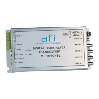
- Page 1 Instruction Manual MT-946C-SL Four Channel Video Transmitter With One Bi-Directional Multi-Protocol Data Channel And One Bi-Directional Contact Closure Channel 10/02/2012 JPK...
- Page 2 Table of Contents Functional Description ................. 3 Installation ....................3 Power Source ....................3 Power Connection ..................4 Fiber Connection ..................4 Video Input Connections ................4 Data Input / Output Connections ..............4 Typical System Data Connections............... 5 Contact Closure Input / Output Connections ..........5 Data Configuration Switches ...............
- Page 3 FUNCTIONAL DESCRIPTION The MT-946C-SL operates as half of a transmitter / receiver pair for the digital transmission of four simultaneous NTSC or PAL video signals along with one channel of field configurable bi-directional data and one channel of bi-directional contact closure over one singlemode fiber optic cable.
- Page 4 POWER CONNECTION Power is supplied to the unit via a two pin terminal connector on the right side of the unit. Follow the label on unit for proper orientation of +12 volt dc and ground. FIBER CONNECTION The fiber optic connection is made via a ST connector located on the right side of the unit. VIDEO INPUT CONNECTIONS The video input connections are made via BNC connectors on the right side of the unit.
- Page 5 Correspondingly, the receiver of an electronic signal is labeled RX or Data In. Following this standard, the Data Out of the copper device is connected to the Data In of the MT-946C-SL. The plus terminal of the copper device is connected to the plus terminal of the MT-946C-SL and the minus is connected to the minus.
- Page 6 In order to reconfigure the RS485/422 channel, the module needs to be opened up. To open the MT-946C-SL, remove the end panel on the terminal block side and remove the screw on the bottom of the module. Slide the PCB assembly out about half way. The configuration switch banks are located at the center of the PCB in line with the DATA 1 terminal block.
- Page 7 Contact Out Pins Open VLI 1 THROUGH VLI 4 A bi-color LED indicator is provided for each of the four video inputs to the MT-946C-SL. DC power and video status associated with each of these LED’s are summarized below. Video Presence LED...
- Page 8 SYNC A bi-color LED indicator is provided to monitor the proper serialization of the electrical data stream through the MT-946C-SL and out onto the fiber. DC power and sync status associated with this LED are summarized below. Sync LED DC Power Status...
Need help?
Do you have a question about the MT-946C-SL and is the answer not in the manual?
Questions and answers