Planet FSD-804P User Manual
8-port 10/100mbps with 4-port poe fast ethernet switch
Hide thumbs
Also See for FSD-804P:
- Datasheet (2 pages) ,
- User manual (18 pages) ,
- User manual (14 pages)

Related Manuals for Planet FSD-804P


Summary of Contents for Planet FSD-804P
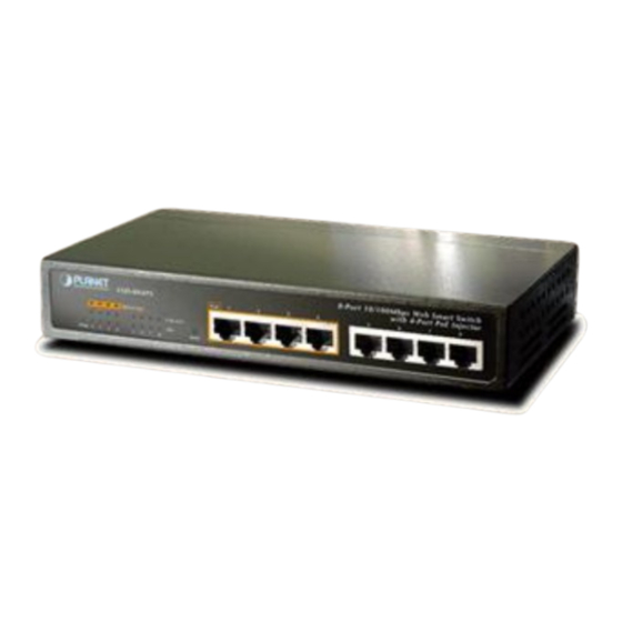
- Page 1 User's Manual FSD-804P 8-Port 10/100Mbps with 4-Port PoE Fast Ethernet Switch - 1 -...
-
Page 2: Fcc Warning
PLANET has made every effort to ensure that this User’s Manual is accurate; PLANET disclaims liability for any inaccuracies or omissions that may have occurred. -
Page 3: Table Of Contents
TABLE OF CONTENTS 1. INTRODUCTION......................4 1.1 C ..............................4 HECKLIST 1.2 H ........................4 OW TO ANUAL 1.3 F ..............................4 EATURES 1.4 S ............................5 PECIFICATION 2. HARDWARE DESCRIPTION ..................6 2.1 P ..........................6 RODUCT ESCRIPTION 2.2 F ............................ -
Page 4: Introduction
1.2 How to Use This Manual The PoE Ethernet Switch User manual is structured as follows: Chapter 2, Installation This chapter explains the functions and how to physically install the FSD-804P. Chapter 3, Switch Operation This chapter explains the switch operation of FSD-804P Chapter 4, Power over Ethernet overview The section explains the IEEE 802.3af Power over Ethernet theories. -
Page 5: Specification
1.4 Specification Model FSD-804P Hardware Specification 8-Port RJ-45 for 10/100Base-TX Network Connector 4-Port with PoE injector function, Port-1 to Port-4 PoE Inject Port One power, 1-4 port PoE in-use, LNK/ACT LED Display 5-8 port LNK/ACT Store and Forward switch architecture Switch Architecture 1.6Gbps... -
Page 6: Hardware Description
Front panel illustrations in this chapter display the unit LED indicators. Before connecting any network device to the FSD-804P, please read this chapter carefully. In the following section, the term “Switch” means the Switch device, ie. FSD-804P; term of “switch” can be any third switches 2.1 Product Description... -
Page 7: Rear Panel
Blinks to indicate that the Switch is actively sending or receiving data over that port. 2.3 Rear Panel The rear panel of the FSD-804P indicates an AC inlet power socket, which accepts input power from 100 to 240VAC, And have a fan hole on the rear panel. -
Page 8: Desktop Installation
2.5 Desktop Installation To install the Switch on desktop, simply follow the next steps: Step1: Attach the rubber feet to the recessed areas on the bottom of the Switch, as shown in Figure 2-3. Attaching the rubber feet to the Fast Ethernet Switch Figure 2-3 Step2: Place the Switch on desktop near an AC power source. -
Page 9: Rack Mounting
2.6 Rack Mounting To install the Switch in a 10-inch standard rack, follow the instructions described below. Step1: Place your Fast Ethernet Switch on a hard flat surface, with the front panel positioned towards your front side. Step2: Attach a rack-mount bracket to each side of the Switch with supplied screws attached to the package. Figure 2-4 shows how to attach brackets to one side of the Switch. -
Page 10: Product Application
Place the FSD-804P on a smooth surface or fasten the mounting brackets purchased separately with the provided screws in a standard 19” rack. Connect the power cord to the power inlet socket of FSD-804P and the other end into the local power source outlet. When the Switch receives power, the Power LED should remain solid Green. - Page 11 2.7.2 Department/ Workgroup PoE Switch: Providing up to 4 PoE, in-line power interfaces, the Switch can easily build a power central-controlled IP phone system, IP camera system, AP group for the enterprise. For instance, 4 camera / AP can be easily installed around the corner in the company for surveillance demands or build a wireless roaming environment in the offices.
-
Page 12: Power Over Ethernet Powered Device
2.8 Power over Ethernet Powered Device Voice over IP phones Enterprise can install POE VoIP Phone, ATA and other Ethernet/non-Ethernet end-devices to the central where UPS is installed for un-interrupt power system 3~5 watts and power control system. Wireless LAN Access Points Museum, Sightseeing, Airport, Hotel, Campus, Factory, Warehouse can install the Access Point any where with no hesitation 6~12 watts... -
Page 13: Switch Operation
No packet loss will occur. 3.5 Auto-Negotiation The STP ports on the FSD-804P switch have built-in "Auto-negotiation". This technology automatically sets the best possible bandwidth when a connection is established with another network device (usually at Power On or Reset). -
Page 14: Power Over Ethernet Overview
4. POWER OVER ETHERNET OVERVIEW What is PoE? Based on the global standard IEEE 802.3af, PoE is a technology for wired Ethernet, the most widely installed local area network technology adopted today. PoE allows the electrical power necessary for the operation of each end-device to be carried by data cables rather than by separate power cords. - Page 15 The data pairs are used. Since Ethernet pairs are transformer coupled at each end, it is possible to apply DC power to the center tap of the isolation transformer without upsetting the data transfer. In this mode of operation the pair on pins 3 and 6 and the pair on pins 1 and 2 can be of either polarity.
-
Page 16: The Poe Provision Process
5. THE POE PROVISION PROCESS While adding PoE support to networked devices is relatively painless, it should be realized that power cannot simply be transferred over existing CAT-5 cables. Without proper preparation, doing so may result in damage to devices that are not designed to support provision of power over their network interfaces. -
Page 17: Start-Up
5.3 Start-up Once line detection and optional classification stages are completed, the PSE must switch from low voltage to its full voltage capacity (44-57 Volts) over a minimal amount of time (above 15 microseconds). A gradual startup is required, as a sudden rise in voltage (reaching high frequencies) would introduce noise on the data lines. -
Page 18: Troubleshooting
Check the LNK/ACT LED on the switch Try another port on the Switch Make sure the cable is installed properly Make sure the cable is the right type Turn off the power. After a while, turn on power again. Why I connect my PoE device to FSD-804P and it cannot power on? Solution: Please check the cable type of the connection from FSD-804(port 1 to port 4) to the other end. -
Page 19: Appendix A Networking Connection
APPENDIX A NETWORKING CONNECTION A.1 DATA OUT PoE Switch RJ-45 Port Pin Assignments (Port 1 to Port-4) PIN NO RJ-45 SIGNAL ASSIGNMENT • Output Transmit Data + • Power + • Output Transmit Data – • Power + • Receive Data + •... - Page 20 There are 8 wires on a standard UTP/STP cable and each wire is color-coded. The following shows the pin allocation and color of straight cable and crossover cable connection: Straight Cable SIDE 1 SIDE2 1 = White / Orange 1 = White / Orange 2 = Orange 2 = Orange SIDE 1...
-
Page 21: Power Over Ethernet Compatibility Test
APPENDIX B B.1 Power over Ethernet Compatibility test PoE Output Note [PLANET POE-151S-12V] + [PLANET ICA-500] 9.6W [PLANET POE-151S-12V] + PLANET ICA310 6.4W Standby [PLANET POE-152S-12V] + [PLANET ICA-500] 7.3W [PLANET POE-151S-12] + CAM-IR338-NT 5.1W LED Off [PLANET POE-151S-12] + CAM-IR338-NT 13.5W~14.3W... -
Page 22: Ec Declaration Of Conformity
: FSD-804P * Produced by: Manufacturer‘s Name : Planet Technology Corp. Manufacturer‘s Address : 11F, No. 96, Min Chuan Road, Hsin Tien Taipei, Taiwan , R. O.C. is herewith confirmed to comply with the requirements set out in the Council Directive on the Approximation of the Laws of the Member States relating to Electromagnetic Compatibility Directive on (89/336/EEC).
Need help?
Do you have a question about the FSD-804P and is the answer not in the manual?
Questions and answers