
Subscribe to Our Youtube Channel
Related Manuals for LevelOne GTL-2660


Summary of Contents for LevelOne GTL-2660
-
Page 1: User Manual
GTL-2660 26-Port L2 Managed Gigabit Ethernet Fiber Switch, 2 Ports SFP Plus 10-Gigabit Ethernet, 4 Ports SFP/RJ45 Combo User Manual V1.0 Digital Data Communications Asia Co., Ltd. http://www.level1.com... - Page 2 Product has been removed or defaced, (5) this warranty will be of no effect if the repair is via anyone other than LevelOne or the approved agents, or (6) In the event of any failures or delays by either party hereto in the performance...
- Page 3 Written approval is NOT a prerequisite to the validity or enforceability of this Agreement and no solicitation of any such written approval by or on behalf of LevelOne shall be deemed as an inference to the contrary.
- Page 4 (5) this warranty will be of no effect if the repair is via anyone other than LevelOne or the authorized agents. The maximum liability of LevelOne under this warranty is confined to the purchase price of the Product covered by this warranty.
-
Page 5: Table Of Contents
Table of Contents Table of Contents TABLE OF CONTENTS ........................I INTRODUCTION ..........................1 ......................1 ANUAL ESCRIPTION ....................1 UNDAMENTAL ONVENTIONS ......................2 ACTORY CONFIGURATION ..........................2 ONTACT PRODUCT OVERVIEW ..................3 CHAPTER 1........................3 RODUCT ROFILE ......................3 EY CHARACTERISTICS ...................... - Page 6 3.3.5.2 Bridge Ports ..........................22 3.3.6 MAC Table ........................23 3.3.7 VLANs .......................... 25 3.3.7.1 Port VLAN ..........................25 3.3.7.2 Port Isolation ........................... 25 3.3.8 QoS ..........................25 3.3.8.1 Port Category ........................... 25 3.3.8.2 Port supervision ........................26 3.3.9 Mirroring ........................26 ..........................
-
Page 7: Introduction
Tip: In order to achieve the best results, it is proposed to upgrade your Windows Internet Explorer browser to Version 6.0 or above. Manual Description GTL-2660 10 Gigabit fiber switch of LevelOne is described in this manual, with the information of its installation, configuration (WEB-based interface) provided. Please read this manual carefully before use. -
Page 8: Factory Configuration
The switch's login name is admin, and its password is admin (both are case-sensitive) in factory configuration. Contact Us If you have any questions during installation or use, please contact us in the following manners. Customer service: 0800-011-110 Levelone discussions: http://www.level1.com E-mail support: support@level1.com http://www.level1.com Page 2... -
Page 9: Chapter 1. Product Overview
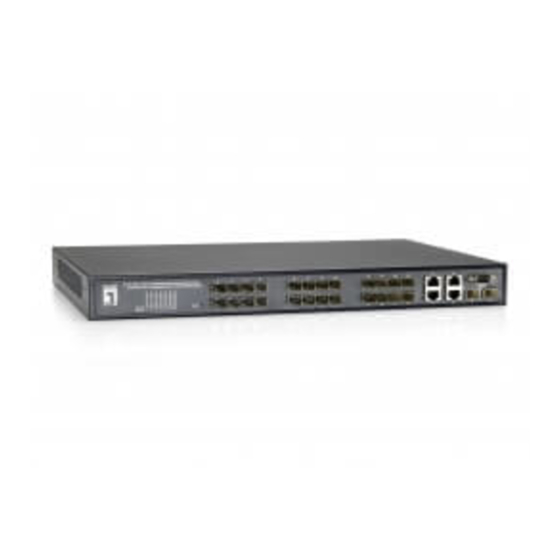
Chapter 1. Product Overview Product Profile The GTL-2660 is a 10 Gigabit fiber switch providing 24 Gigabit SFP ports, four Combo ports (RJ-45/SFP), as well as two 10 Gigabit SFP+ ports. This high-performance intelligent managed gigabit switch provides high capacity data transfer for high volume deployments such as data centers, government facilities and internet cafes. -
Page 10: Physical Specifications
5%~90%, no condensation Table 1-1 Physical specifications Product appearance GTL-2660 front panel consists of LEDs, ports, Reset button and Console port. Here is a detailed description of the appearance of the switch with GTL-2660 as the example (as shown in Figure 1-1). - Page 11 Ports 25 and 26 are 10 Gigabit SFP+ ports; Figure 1-1 GTL-2660 front panel Figure 1-2 GTL-2660 rear panel...
-
Page 12: Chapter 2. Hardware Installation
Chapter 2 Hardware Installation Chapter 2. Hardware Installation Precaution for installation Before installing the switch, you must ensure that the switch is powered off. And follow the precaution for installation: Make sure to install the working table and standard rack in a stable manner; ... -
Page 13: To Establish A Network Connection
Chapter 2 Hardware Installation Secure the L-shaped brackets on the guide slots (as shown in the figure below) fixed at both ends of the rack, to ensure that the switch can be mounted on the rack in a stable, horizontal manner; Figure 2-1 Rack Installation To establish a network connection To establish network connection: Insert the appropriate media into the ports of the device to... -
Page 14: Chapter 3. Web Management
Chapter 3. WEB Management Log in to the management page With the WEB interface, you can manage and maintain the GTL-2660 switch in a very intuitive manner. Before the configuration of the switch via the WEB interface, confirm the following points. -
Page 15: Introduction Of Web Interface
Figure 3-2 Enter the user name and password Introduction of WEB interface Tips: The features in this manual are described with the WEB management interface of GTL-2660. For example; the management interface for GTL-2660 is similar, and is not described here. Figure 3-3 Home of WEB interfaces... - Page 16 Chapter 3 WEB Management Structure of WEB management interface The device-related information is provided above the WEB page, including: Hiper logo hyperlink, device model, version, etc. Click on "Help" link to enter the online help page, and view the meaning of functional parameters of the device. The menu bar is on the left of the WEB page.
-
Page 17: Configuration
Chapter 3 WEB Management Ports Display the traffic statistics of all ports. Display the status of LACP ports, statistics of port packets LACP and other information. Display the status of STP ports, statistics of port packets Spanning Tree and other information. ICMP Ping Ping test Test the network connectivity. -
Page 18: Ip & Time
Chapter 3 WEB Management Figure 3-5 Configuration of system information System Contact: Sets the Administrator's contact information, such as name, contact information, etc. System contacts may only contain printable ASCII characters (codes from 32 to 126), and they cannot exceed 255 characters in length. - Page 19 Chapter 3 WEB Management DHCP request; if it receives no response from the DHCP server within about 35 seconds, and the IP address is set to a non-zero value, the switch will disable the DHCP client function, and directly use the configured IP address. In addition, the switch as a DHCP client will also announce its own host name (that is, the configured system name) on the local network for use in DNS query.
-
Page 20: Port Configuration
Chapter 3 WEB Management 3.3.2 Port configuration Page Wizard: Configuration—> Ports In this page, you can configure and view port parameters, and view the current port status information. Figure 3-7 Port configuration Port: Displays the port number of the switch. ... -
Page 21: Security
Chapter 3 WEB Management 1000-X: To set a Combo port to enforce SFP optical port, and the working mode to 1000M full duplex. At this point, the corresponding port is disabled. 1000-X_AMS: To set a Combo port to working in the AMS mode and SFP optical port in priority, and the working mode of the SFP optical port to 1000M full duplex, and that of the electrical port to the auto-negotiation mode (the default working mode for the Combo port). -
Page 22: Access Manage
Chapter 3 WEB Management Figure 3-8 Settings of logon password 3.3.3.2 Access Manage Page Wizard: Configuration—> Security—> Access Manage This page allows you to configure the access restrictions of the switch. In the list of access restrictions, you can create up to 16 entries. After the access restrictions of the switch are enabled, only the hosts (based on IP address ranges) added into the access restrictions list to access the switch in a specified manner. - Page 23 Chapter 3 WEB Management Figure 3-10 SNMP system configuration Mode: To enable or disable the SNMP functions of the switch. Version: To set the SNMP version number the system enables, and the options include: SNMP v1, SNMP v2c, SNMP v3. ...
- Page 24 Chapter 3 WEB Management Figure 3-12 SNMPTrap configuration (2) Trap Mode: To enable or disable the SNMP Trap function. Trap Version: To specify which version of SNMP Trap messages the switch sends. Trap Community: To set the community name that a switch uses to send Trap messages to the SNMP network management software.
-
Page 25: Aggregation
Chapter 3 WEB Management detection", the system will automatically detect and use the engine ID, otherwise, the system will use the value set here. Trap security engine ID is a hexadecimal number string, whose length must be an even number from 10 to 64, but not all 0 or all F. -
Page 26: Lacp
Chapter 3 WEB Management Figure 3-14 Configuration of Aggregation Groups Group ID: Displays the aggregation group ID. The ports in "Normal" group are normal ports, which means not for port aggregation. A switch port can only belong to one aggregation group. ... -
Page 27: Spanning Tree
Chapter 3 WEB Management The management Key can be generated automatically by the system, or manually configured. It is automatic by default, which means that the switch will automatically set Key values according to the physical link rate of ports, in which the Key values corresponding to the rates 10M, 100M and 1000M are 1, 2 and 3 respectively;... -
Page 28: Bridge Ports
Chapter 3 WEB Management Bridge Priority: To set the switch of the network bridge priority. The smaller the value is, the higher the priority is. The network bridge priority and the MAC addresses of switches form a network bridge ID. After an exchange of BPDU, the devices with the smallest network bridge ID will be selected as the root bridge. -
Page 29: Mac Table
Chapter 3 WEB Management port. Upon selecting "Manual", the user can manually enter the path overhead value. If there are no special needs, it is not necessary to modify it. Value range is 1~200000000. Priority: To set the port priority. When the path overhead is the same, the ports with higher priorities will be selected as the root port. - Page 30 Chapter 3 WEB Management Figure 3-18 Configuration of MAC address table Disable Automatic Aging: Checking means the MAC addresses learned by the switch will not be aged. Aging Time: To set the aging time of MAC addresses, whose value range is 10~1000000 seconds.
-
Page 31: Vlans
Chapter 3 WEB Management Port: To select the port bound by the MAC address. 3.3.7 VLANs 3.3.7.1 Port VLAN Page Wizard: Configuration—>VLANs—> Port VLAN The Port VLAN page allows you to view and modify the port VLAN configuration of the switch, including: create or delete a port VLAN, and add or delete member ports for the port VLAN. -
Page 32: Port Supervision
Chapter 3 WEB Management parameters for each port on the switch. Figure 3-21 QoS ingress port classification Port: Displays the port number of the switch. QoS class : To set the default QoS class of the port, which will be classed into this category after receiving a data frame. -
Page 33: Monitor
Chapter 3 WEB Management In the monitoring configuration page, you can set the port mirroring function. With the port mirroring function, you can copy the flow of the monitoring port to the monitoring port, to provide the detailed information on the transmitting status of the monitored ports, allowing network managers to make traffic monitoring, performance analysis and troubleshooting. -
Page 34: System
Chapter 3 WEB Management 3.4.1 System 3.4.1.1 Information Page Wizard: Monitoring—> System—> Information This page allows you to view the system information of the switch. Figure 3-24 Basic Information of the system Contact: Displays the system contacts of the switch, which is set in Configuration—>System—>Information Page. -
Page 35: Ports
Chapter 3 WEB Management Figure 3-25 CPU loading 3.4.2 Ports 3.4.2.1 State Page Wizard: Monitor—> Ports—> State This page provides the diagram of the front panel ports of the switch, visually displaying the current status of each switch port. The port displayed as gray indicates the port is disabled;... -
Page 36: Detailed Statistics
Chapter 3 WEB Management This page displays the summary of traffic statistics of all ports. Figure 3-27 Port flow overview Port: Displays the port number of the switch. Packets: Displays the number of incoming/outgoing packets from / to the corresponding ports. - Page 37 Chapter 3 WEB Management Figure 3-28 Statistics of port data Port: To select the port that needs to view detailed statistics. Rx Packets: Displays the number of incoming/outgoing packets from / to the port. Rx Octets: Displays the number of incoming/outgoing bytes from / to the port, including bad packets and FCS fields, but excluding framing bits.
-
Page 38: Lacp
Chapter 3 WEB Management of buffer space for transmission. Tx Late/Exc. Coll.: Displays the number of data frames discarded by the port because of lag or excessive conflicts. Tip: Refresh, clear button actions will only affect the currently selected port. 3.4.3 LACP 3.4.3.1... -
Page 39: Port Statistics
Chapter 3 WEB Management Figure 3-30 LACP port status information Port: Displays the port number of the switch. LACP: Displays the working status of the LACP on the port. "Enable" indicates that the protocol is enabled on the port, and the port link is Up. "Disable" indicates that the LACP Protocol is not enabled on the port or the port link is Down. -
Page 40: Spanning Tree
Chapter 3 WEB Management Figure 3-31 Statistics of LACP port status Port: Displays the port number of the switch. LACP Received: Displays the number of the LACP packets received by the ports. LACP Transmitted: Displays the number of the LACP packets sent by the ports. ... -
Page 41: Port Statistics
Chapter 3 WEB Management For other network bridges (switches), the value is the sum of all port path overheads on the best path (that is, the shortest path) to the root bridge. Root port: Displays the port number selected as the root port. ... -
Page 42: Port Statistics
Chapter 3 WEB Management Figure 3-33 Port Statistics 3.4.4.3 Port Statistics Page Wizard: Monitor—> Spanning Tree—> Port Statistics This page allows you to view the STP port statistics of the switch. Figure 3-34 Port Statistics Port: Displays the port number of the switch. ... -
Page 43: Maintenance
Chapter 3 WEB Management Figure 3-35 ICMP Ping IP address: To set the IP address of the destination node to be detected. Ping Length: To set the length of the ICMP packet (excluding the IP and ICMP headers) to be sent. Value range is 2~1452 bytes. ... -
Page 44: Factory Defaults
Chapter 3 WEB Management On this page, you can restart the switch. If you are sure to reboot the device, please click "Yes" button. Figure 3-37 Restart Device 3.6.2 Factory Defaults Page Wizard: Maintenance—> Factory Defaults In this page, you can restore the switch to its factory configuration. If you determine to restore the device to its factory configuration, please click "Yes"... -
Page 45: Configuration Management
Chapter 3 WEB Management upgrades may be interrupted; do not disconnect the power, shut down or reboot the switch, otherwise it will cause damage to the switch, making it fail to work properly. Upgrade: first, click on "Browse" to select the upgrade files, and then click on "Upgrade"... -
Page 46: Appendix Adecimal Ascii Code Table
Appendix A Decimal ASCII code table Appendix A Decimal ASCII code table Characters Space " & Characters Characters < > Characters Characters Characters Characters Characters http://www.level1.com Page 40... -
Page 47: Appendix Bfigure Index
Appendix B Figure Index Appendix B Figure Index Figure 1-1 GTL-2660 front panel .................. 5 Figure 1-2 GTL-2660 rear panel ................... 5 Figure 2-1 Rack Installation ..................7 Figure 3-1 Enter your login address ................8 Figure 3-2 Enter the user name and password ............9 Figure 3-3 Home of WEB interfaces ................ - Page 48 Appendix B Figure Index Figure 3-38 Restore the factory settings ..............38 Figure 3-39 Software upgrade ..................38 Figure 3-40 Exit the system ..................39 http://www.level1.com Page 42...
Need help?
Do you have a question about the GTL-2660 and is the answer not in the manual?
Questions and answers