
Related Manuals for LevelOne GEL-2461


Summary of Contents for LevelOne GEL-2461
-
Page 1: User Manual
GEL-2461 24-Port L2 Managed Gigabit Ethernet Switch, 16 Ports SFP User Manual V1.0 Digital Data Communications Asia Co., Ltd. http://www.level1.com... - Page 2 Product has been removed or defaced, (5) this warranty will be of no effect if the repair is via anyone other than LevelOne or the approved agents, or (6) In the event of any failures or delays by either party hereto in the performance...
- Page 3 Written approval is NOT a prerequisite to the validity or enforceability of this Agreement and no solicitation of any such written approval by or on behalf of LevelOne shall be deemed as an inference to the contrary.
- Page 4 Table of Contents defaced, or (5) this warranty will be of no effect if the repair is via anyone other than LevelOne or the authorized agents. The maximum liability of LevelOne under this warranty is confined to the purchase price of the Product covered by this warranty.
-
Page 5: Table Of Contents
Table of Contents Table of Contents Product Overview ..................... 1 Chapter 1 Key Features ..........................1 Technical Specification ......................2 Physical Characteristics ......................3 1.3.1 Front Panel ........................3 1.3.2 Rear Panel........................4 Chapter 2 Hardware Installation ....................5 Installation Requirements ......................5 Installing the Switch ........................ - Page 6 Table of Contents 5.3.1 RSTP Bridge Overview ....................19 5.3.2 RSTP Port Status ......................20 LACP Status........................... 21 5.4.1 LACP Aggregation Overview ..................21 5.4.2 LACP Port Status ......................22 Basic ......................... 23 Chapter 6 Setup Wizard .......................... 23 System Settings ........................23 Port Settings ...........................
- Page 7 Table of Contents 8.4.1 Introduction to DHCP Snooping ................... 53 8.4.2 IP Filtering Settings ....................... 54 IP/MAC Binding ........................54 8.5.1 IP/MAC Binding ......................55 8.5.2 The Operation Principle of IP/MAC Binding ..............55 8.5.3 IP/MAC Binding Settings ....................56 8.5.4 IP/MAC Binding List ....................
-
Page 8: Chapter 1 Product Overview
The device is a Layer 2 wire-speed Ethernet switch, perfect for deployments in small and medium businesses, branch offices, and for running essential business services. GEL-2461 offers 8 x 10/100/1000M auto-negotiation ports and 16 SFP combo ports. All RJ-45 ports support auto MDI/MDI-X, with SNMP and Full/Half duplex transfer mode for 10 and 100Mbps ports as well as Full duplex transfer mode for 1000Mbps ports. -
Page 9: Technical Specification
Chapter 1 Product Overview Supports IEEE 802.1Q tag-based VLAN Supports shared VLAN Supports static link aggregation Supports Link Aggregation Control Protocol (LACP) Supports ARP spoofing prevention Supports port mirroring, user-defined mirroring port and mirrored port(s) ... -
Page 10: Physical Characteristics
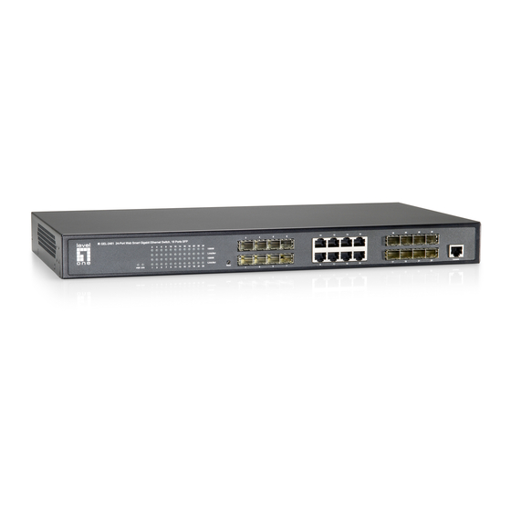
Physical Characteristics 1.3.1 Front Panel As shown in Figure 1-1, the front panel of the GEL-2461 Switch contains the LEDs, 8 10/100/1000M RJ-45 ports, 16 Gigabit SFP combo ports, a Reset button, and a Console port. Figure 1-1 Front Panel of GEL-2461 Note The product pictures shown in Figure 1-1 and Figure 1-2 are for reference only. -
Page 11: Reset Button
Chapter 1 Product Overview 1. LEDs Full Name Status and Description The LED lights steady when the power is being supplied to the Power LED Switch. The LED flashes slowly when the Switch is operating properly. System LED The LED will extinguish or light steady if a fault has occurred in the Switch. -
Page 12: Chapter 2 Hardware Installation
Chapter 2 Hardware Installation Chapter 2 Hardware Installation Installation Requirements Before you install the Switch, observe the following guidelines: Make sure that the Switch is powered off. Make sure that the workbench or rack is level and stable. ... -
Page 13: Installing The Switch On A Level Surface
Turn the Switch over to make it right side up on the flat surface. Connecting Network Devices To connect network devices to the GEL-2461 Switch, follow these steps: Step 1 Make sure all devices you will connect to the Switch are powered off. -
Page 14: Connecting The Power
Switch from working abnormally or being damaged, make sure that the power supply and connectivity are normal, and the power outlet is grounded properly before powering on the Switch. The GEL-2461 Switch does not have an on/off switch. To supply power to the Switch, follow these steps: Step 1 Connect one end of the power cord to the power connector on the rear panel of the Switch. -
Page 15: Chapter 3 Logging In To The Switch
Chapter 3 Logging in to the Switch Chapter 3 Logging in to the Switch You can configure and manage the Switch through an intuitive and easy-to-use Web UI. Before configuring the Switch via Web UI, you need to properly install and configure TCP/IP properties on the computer that you use to administer the Switch. -
Page 16: Introduction To Web Ui
Chapter 3 Logging in to the Switch Figure 3-1 Entering IP address in the Address Bar When you login to the Switch, the default password is admin, click OK. See Figure 3-2. Figure 3-2 Login Screen Introduction to Web UI 3.3.1 Introduction to Menu Items Figure 3-3 Main Menu Bar... - Page 17 Chapter 3 Logging in to the Switch level menu item serves as a link to one Web page. The following table lists all of the first level menu items together with their submenu items, and the feature description. Using this table, you can quickly find the features you want to configure. First Level Second Level Feature Description...
-
Page 18: Description Of Common Buttons
Chapter 3 Logging in to the Switch IP Filtering It allows you to configure IP filtering and DHCP snooping. It allows you to configure IP/MAC bindings to prevent ARP IP/MAC Binding spoofing attacks. It allows you to enable device access restriction, and specify a Access Restriction range of computers that are exempt from the restriction. -
Page 19: Chapter 4 Setup Wizard
Chapter 4 Setup Wizard Chapter 4 Setup Wizard The Setup Wizard will guide you to quickly configure the basic features of the Switch, which include password, IP address, switch type, link aggregation group and port mirroring settings. Password Settings The Switch’s default password is blank. To ensure security, it is strongly recommended that you set the password, remember your new password and keep it safe. -
Page 20: Ip Address Settings
Chapter 4 Setup Wizard IP Address Settings Figure 4-2 Setup Wizard - IP Address Settings Enable DHCP Client: It allows you enable or disable DHCP client. If you select the check box to enable DHCP client, the Switch will automatically obtain an IP address, subnet mask and default gateway address from a DHCP server available on your LAN. -
Page 21: Link Aggregation Group Settings
Chapter 4 Setup Wizard the network. The edge switch is connected to end-user hosts. Core Switch: A core switch is located in the core of the network and serves to interconnect edge switches. Link Aggregation Group Settings This page provides a predefined LAG (Link Aggregation Group).When you choose Edge Switch in the Setup Wizard –... -
Page 22: Security Binding
Chapter 4 Setup Wizard Note If you configure LAG here, it will clear the LAGs already configured. Security Binding If you choose Edge Switch in the Setup Wizard - Switch Type Settings page, after setting the LAG, the Setup Wizard – Security Binding will appear, see Figure 4-7. - Page 23 Chapter 4 Setup Wizard external network analyzer. Then the administrator can perform traffic monitoring, performance analysis and fault diagnosis. On the Switch, any port can act as the mirroring port, which is used to capture traffic of another port. As traffic can be captured from more than one port simultaneously, you can have one mirroring port and several other ports being monitored.
- Page 24 Chapter 4 Setup Wizard Select All: It is used to select or clear all the Mirrored Port check boxes, except the check box for the Mirroring Port. Note Do not forget to click the Finish button to save the changes you have made in the Setup Wizard, else these changes will be discarded.
-
Page 25: Chapter 5 Status
Chapter 5 Status Chapter 5 Status Summary Statistics This page displays summary traffic statistics on a port-by-port basis, which include the number of transmitted/received bytes, packets, non-unicast packets, and so on. You can use the statistics to monitor and analyze the system status. Figure 5-1 Summary Statistics Port: It displays the port number. -
Page 26: Port Statistics
Chapter 5 Status Tx Bytes: It displays the total number of bytes transmitted by the port. Tx Packets: It displays the total number of packets transmitted by the port. Rx Bytes: It displays the total number of bytes received by the port. Rx Packets: It displays the total number of packets received by the port. -
Page 27: Rstp Port Status
Chapter 5 Status Bridge ID: It displays the Switch’s Bridge ID (BID), which consists of the bridge priority and MAC address of the Switch. Hello Time: It displays the Hello Time configured in the Advanced > RSTP page. Max Age: It displays the Max Age configured in the Advanced > RSTP page. Forward Delay: It displays the Forward Delay configured in the Advanced >... -
Page 28: Lacp Status
Chapter 5 Status ● Blocking: It indicates that the port is currently blocked. In this state, the port can receive and process BPDUs, but it cannot forward user frames. ● Listening: It indicates that the port is listening for a BPDU from neighboring bridge(s) in order to determine the new topology. -
Page 29: Lacp Port Status
Chapter 5 Status 5.4.2 LACP Port Status Figure 5-5 LACP Port Status Port: It displays the port number on the local Switch. Protocol Active: It indicates if LACP is enabled and running on the port. If LACP is enabled and running on the port, it displays Yes. Else, it displays No. Partner Port: It displays the port number on the partner switch. -
Page 30: Chapter 6 Basic
Chapter 6 Basic Chapter 6 Basic Setup Wizard Please refer to Section 4 Setup Wizard for detailed information. System Settings In the Basic > System Settings page, you can view the basic system information of the switch(see Figure 6-1 ), configure DHCP relay agent, DHCP client, IP address, subnet mask, default gateway, VLAN ID, MAC address aging time, password, and so on, see Figure 6-2. - Page 31 Chapter 6 Basic address, subnet mask and default gateway address of the Switch. DHCP Server: It displays the DHCP Server’s IP address of the Switch. Lease Left: It displays the time remaining until the current IP address lease expires. Figure 6-2 System Settings System Date: It specifies the current system date.
- Page 32 Chapter 6 Basic IP Address and Subnet Mask: They specify the IP address and subnet mask of the Switch. You can use this IP address to access and manage the Switch. To facilitate management, please assign the Switch an IP address within your LAN subnet in most cases.
-
Page 33: Port Settings
Chapter 6 Basic Switch automatically obtain them from a DHCP server available on your LAN. Port Settings In the Basic > Port Settings page, you can view the link status of each port, configure the port speed and duplex mode, maximum frame, flow control, enable or disable port protection and MAC address learning for each port. -
Page 34: Port Mirroring
Chapter 6 Basic 10M/FDX, 100M/HDX, 100M/FDX, 1000M/FDX, and Disabled. The default value is Auto, which means the port will auto negotiate the speed and duplex mode with the remote port on the link. If you want to disable a port, please select Disabled. Maximum Frame: It specifies the maximum frame size supported by the port. - Page 35 Chapter 6 Basic another port. As traffic can be captured from more than one port simultaneously, you can have one mirroring port and several other ports being monitored. Figure 6-4 Port Mirroring Mirroring Port: It specifies the capture port that will mirror the traffic of the mirrored port(s).
-
Page 36: Chapter 7 Advanced
Chapter 7 Advanced Chapter 7 Advanced VLAN A VLAN (Virtual Local Area Network) is a group of devices that form a logical LAN segment, that is, a broadcast domain. The members on the same VLAN can communicate with each other. The traffic will not disturb among different VLANs, that is, any traffic (unicast, broadcast or multicast) within a VLAN doesn’t flow to another VLAN. - Page 37 Chapter 7 Advanced same VLAN can communicate with each other, but they are unable to communicate with ports on different VLANs. End-user hosts become members in a VLAN based on the switch port to which they are connected. To enable port-based VLAN on the Switch, select Port VLAN from the VLAN Mode drop-down list, and then click the Save button.
- Page 38 Chapter 7 Advanced 7.1.2.2 Port-based VLAN List In the Advanced > VLAN page, you can view and edit Port VLAN List, see Figure 7-3. Click the VLAN ID, you can modify this vlan. Figure 7-3 Port-based VLAN List Note You can edit VLAN 1 (the default VLAN), but you cannot delete it. 7.1.2.3 An Configuration Example for Port-based VLAN In this example, it is required that Port 1 and Port 2 can communicate with each other,...
-
Page 39: Tag-Based Vlan
Chapter 7 Advanced 7.1.3 Tag-based VLAN The 802.1Q tag-based VLAN add a tag to the header of the packets to classify their VLANs. An 802.1Q tag-based VLAN is a group of ports located anywhere on the network, acting as part of the same physical segment. On the Switch, you can manually assign the ports to multiple VLANs, and then configure VLAN parameters for each port. - Page 40 Chapter 7 Advanced Figure 7-6 Tag-based VLAN Settings Port: It indicates the port number. Members: It allows you to choose one or more ports as the members of the LAG. Select a check box to add a port to the LAG, or clear the check box to remove the port from the LAG.
-
Page 41: Vlan Port Settings
Chapter 7 Advanced 7.1.3.2 Tag-based VLAN List In the Advanced > VLAN page, you can select the Tag VLAN List tab to view and edit Tag VLAN List, see Figure 7-7. Figure 7-7 Tag-based VLAN List Modify: To modify a configured tag-based VLAN, select a VLAN ID, then click Modify button. - Page 42 7.1.3.4 An Configuration Example for Tag-based VLAN In this example, a business uses a HiPER Router to access the Internet. A GEL-2461 Switch’s Port 1 is connected to the Router’s LAN Port 1, PC1 (management host) is connected to the Router’s LAN Port 5, and PC2 is connected to the Switch’s Port 2.
-
Page 43: Rstp
Chapter 7 Advanced Step 2 On the GEL-2461 Switch, add a new tag-based VLAN: VLAN ID is 2, and port members are Port 1 and Port 2. RSTP The Spanning Tree Protocol (STP) is a link layer network protocol that detects and eliminates loops in a bridged or switched network. -
Page 44: Rstp Port Settings
Chapter 7 Advanced discarding it. If this timer expires before the port receives a new BPDU, the port transitions to the listening state. The default value is 20 seconds. Forward Delay: It specifies the amount of time that a bridge remains in the listening and learning states before forwarding packets. -
Page 45: Lacp
Chapter 7 Advanced LACP 7.3.1 Introduction LACP Link Aggregation Control Protocol (LACP) is part of IEEE 802.3ad which is used to bundle several physical ports together to form a single logical channel, known as a Link Aggregation Group (LAG) or bundle. LACP allows two switches to exchange Link Aggregation Control Protocol Data Units (LACPDUs) to negotiate a LAG automatically. -
Page 46: Lacp Settings
Chapter 7 Advanced For example, if you want to aggregate Port 2, 3, 4 and 5 on the local GEL-2461 Switch and those on the remote switch together to form a dynamic LAG, you only need to enable LACP on Port 2, 3, 4 and 5 respectively, and leave their Admin Key at the default value of auto, see Figure 7-12. -
Page 47: Qos
Chapter 7 Advanced Quality of Service (QoS) is a technology which uses various mechanisms to decrease the negative effects of network congestion to improve network performance. For example, using QoS can guarantee a required delay and packet dropping probability to various real-time applications (video, audio, etc.) when network congestion occurs. -
Page 48: Port-Based Priority Settings
Chapter 7 Advanced Figure 7-14 802.1p Priority Settings QoS Mode: It specifies the QoS mode that you want to enable on the Switch. The options are QoS Disabled, 802.1p and Port-based Priority. Here please select 802.1p. Global Priority: It is used to set all 802.1p values to the same priority level. -
Page 49: Link Aggregation
Chapter 7 Advanced Figure 7-15 Port-based Priority Settings QoS Mode: It specifies the QoS mode that you want to enable on the Switch. The options are QoS Disabled, 802.1p and Port-based Priority. Here please select Port-based. Global Priority: It is used to set all ports to the same priority level. Port: It indicates the port number. -
Page 50: Link Aggregation Settings
Chapter 7 Advanced total bandwidth is approximately the sum of the individual switch ports. For example, there is a 100Mbps switch device, a LAG containing two ports will have 200Mbps bandwidth, and a LAG containing four ports will have 400Mbps bandwidth. Link aggregation provides a higher performance logical link, as well as providing a fault-tolerant link between two devices. -
Page 51: Linkage Management
Chapter 7 Advanced All ports in a LAG must belong to the same VLAN, and must have the same tag VLAN port settings (configured in the Advanced > VLAN > VLAN Port Settings page) if you enable tag-based VLAN on the Switch. A LAG can’t contain the mirroring port. - Page 52 Chapter 7 Advanced Port: It displays the local Switch’s port to which the remote switch is connected. Password: It specifies the login password of the remote switch. Please enter the correct password, otherwise you cannot manage and configure the remote switch. Remote Operation: Including IP Settings, Rate Limiting, Port Protection, IP/PORT Banding, MAC/PORT Binding, Save Settings, Check MAC Address.
- Page 53 Chapter 7 Advanced Note So far, the Switch cannot discover the switches from other companies. And it can only discover the same model of switches from UTT Technologies Co., Ltd. To configure a remote switch, please enter the correct password. Otherwise the settings will not take effect, and you will be prompted that the operation failed due to a wrong password.
-
Page 54: Chapter 8 Security
Chapter 8 Security Chapter 8 Security Security Log In the Security > Security log page, you can view various types of security log messages, such as ARP spoofing, MAC move, and so on. The log messages are listed in reverse chronological order of creation (i.e., most recent at the top). -
Page 55: Mac/Port Binding
In addition, a static address doesn’t age and must be manually removed. On the GEL-2461 Switch, static MAC address is also called MAC/Port binding. If a computer’s MAC address is bound to a port of the Switch, the computer must be connected to that port in order to communicate with the Switch. -
Page 56: Mac/Port Binding Settings
Chapter 8 Security 8.2.3 MAC/PORT Binding Settings Figure 8-2 MAC/Port Settings MAC Address: It specifies the MAC address to be bound. Port: It specifies the port to be bound. The range is 1 to 24. Save: Click to save your changes. Cancel: Click to revert to the last saved settings. -
Page 57: Mac/Port Binding List
Chapter 8 Security 8.2.4 MAC/PORT Binding List Figure 8-3 MAC/Port Binding List Port Protection: It allows you to enable or disable port protection on the port. If you select the check box to enable port protection on a port, the port will no longer learn any new MAC address, and only forward the packets whose desination MAC addresses have been added to the MAC/Port Binding List. -
Page 58: Rate Limiting
Chapter 8 Security Bing All IP/MAC/PORT: To binding all the dynamically learned IP Address, MAC addresses and their associated port, and it should configure the Gateway Address. Delete All IP/MAC/PORT: To delete all IP/MAC/PORT bindings. Disalbe Port Protection on all Ports: To disable port protection on all ports. Note If a computer’s MAC address is bound to a port of the Switch, the computer must be connected to that port in order to communicate with the Switch. -
Page 59: Rate Limiting
Chapter 8 Security Figure 8-4 Storm Control ICMP Rate: It specifies the maximum rate (packets per second) at which ICMP packets are forwarded. Broadcast Rate: It specifies the maximum rate (packets per second) at which broadcast packets are forwarded. Multicast Rate: It specifies the maximum rate (packets per second) at which the multicast packets are forwarded. -
Page 60: Ip Filtering
Chapter 8 Security Egress Rate: It specifies the maximum rate (kilobits per second) of egress traffic on the port. IP Filtering 8.4.1 Introduction to DHCP Snooping The Switch supports DHCP snooping to prevent DHCP spoofing attacks. DHCP spoofing attacks occur when an attacker masquerades as a valid DHCP server to reroute traffic to his machine, by advertising itself as the default gateway or DNS server. -
Page 61: Ip Filtering Settings
Chapter 8 Security 8.4.2 IP Filtering Settings Figure 8-6 IP Address Filtering Port: It indicates the port number. Mode: It specifies the mode of IP filtering. The options are Disabled, Static IP and DHCP. Disabled: It means that IP address filtering is disabled on the port. This option is selected by default. -
Page 62: Ip/Mac Binding
Chapter 8 Security 8.5.1 IP/MAC Binding The Switch provides IP/MAC binding feature to implement user identification. Using the IP/MAC address pair as a unique user identity, you can protect the Switch and your network against IP spoofing attacks. IP spoofing attack refers to that a computer attempts to use another trusted computer’s IP address to communicate with the Switch. -
Page 63: Ip/Mac Binding Settings
Chapter 8 Security 8.5.3 IP/MAC Binding Settings Figure 8-7 IP/MAC Binding Settings IP Address: It specifies the IP address to be bound. MAC Address: It specifies the MAC address to be bound. Save: Click to save your changes. Cancel: Click to revert to the last saved settings. Subnet Network: Select a port number from the drop-down list first, then click the Subnet Network button, the Switch will immediately scan the specified port(s), learn and display dynamic ARP information (that is, IP and MAC address pairs) in the list... -
Page 64: Ip/Mac Binding List
Chapter 8 Security 8.5.4 IP/MAC Binding List Figure 8-8 IP/MAC Binding List Modify a IP/MAC Binding: To modify a configured IP/MAC binding, click the IP address, the related information will be displayed in the setup page. Then modify it, and click the Save button. Delete: To delete more than one IP/MAC binding at a time, select the leftmost check boxes of the IP/MAC bindings you want to delete, and then select Delete from the drop-down list in the lower right corner of the list, lastly click the Save button. -
Page 65: Access Restriction
Chapter 8 Security Note If you want to clear the Allow Undefined LAN PCs check box to block the undefined local computers from communicating with the Switch, please make sure that you have added the IP/MAC address pair of the computer that you use to administer the Switch into the IP/MAC Binding List. -
Page 66: Chapter 9 Administration
Appendix A Contact Information Chapter 9 Administration Configuration Figure 9-1 Configuration Backup and Restore Configuration Update: Click the Browse button to choose an appropriate configuration file or enter the file path and name in the text box, then click Update button. -
Page 67: Firmware Upgrade
Note Before you upgrade the firmware, please download the latest firmware from the website of levelone technologies co. ltd. It is suggested that you reset the Switch to factory default settings before upgrade. It is strongly suggested that you upgrade the firmware when the Switch is under light load. -
Page 68: Restart
Appendix A Contact Information Restart Click the Restart, you can restart the switch. Exit Click the Exit, you can exit the web configuration interface. http://www.level1.com Page 61... -
Page 69: Appendix A Contact Information
Appendix A Contact Information Appendix A Contact Information If you have any questions regarding the operation or installation of the GEL-2461 Switch, please contact us in any of the following ways. Technical Support Phone: +886-0800-011-110 LEVELONE Forum: http://www.level1.com/ ... -
Page 70: Appendix B Figure Index
Appendix B Figure Index Appendix B Figure Index Figure 1-1 Front Panel of GEL-2461 ..................3 Figure 1-2 Rear Panel of the Switch ..................4 Figure 2-1 Installing the Switch in a Rack ................6 Figure 3-1 Entering IP address in the Address Bar ..............9 Figure 3-2 Login Screen ...................... - Page 71 Appendix B Figure Index Figure 7-17 Remote Switch Discovery List ................44 Figure 9-1 Security Log ......................47 Figure 9-2 MAC/Port Settings ....................49 Figure 9-3 MAC/Port Binding List ..................50 Figure 9-4 Storm Control ......................52 Figure 9-5 Rate Limiting ......................52 Figure 9-6 IP Address Filtering ....................
-
Page 72: Appendix C Table Index
Appendix C Table Index Appendix C Table Index Table 1-1 Technical Specification ..................... 3 Table 1-2 Description of LEDs on the Front Panel ..............4 Table 3-1 Description of Menu Items ..................11 Table 3-2 Description of Common Buttons ................11 http://www.level1.com Page 65...
Need help?
Do you have a question about the GEL-2461 and is the answer not in the manual?
Questions and answers