Table of Contents
Advertisement
Quick Links
www.freeservicemanuals.info
[ 1 ] GENERAL . . . . . . . . . . . . . . . . . . . . . . . . . . . . . . . . . . . . . . . . . . . . 1 – 1
[ 2 ] SPECIFICATIONS . . . . . . . . . . . . . . . . . . . . . . . . . . . . . . . . . . . . . . 2 – 1
[ 3 ] CONSUMABLE PARTS . . . . . . . . . . . . . . . . . . . . . . . . . . . . . . . . . . 3 – 1
[ 4 ] EXTERNAL VIEWS AND INTERNAL STRUCTURE . . . . . . . . . . . . 4 – 1
[ 5 ] UNPACKING AND INSTALLATION . . . . . . . . . . . . . . . . . . . . . . . . 5 – 1
[ 6 ] COPY PROCESS . . . . . . . . . . . . . . . . . . . . . . . . . . . . . . . . . . . . . . . 6 – 1
[ 7 ] OPERATIONAL DESCRIPTIONS . . . . . . . . . . . . . . . . . . . . . . . . . . 7 – 1
[ 8 ] DISASSEMBLY AND ASSEMBLY . . . . . . . . . . . . . . . . . . . . . . . . . . 8 – 1
[ 9 ] ADJUSTMENTS . . . . . . . . . . . . . . . . . . . . . . . . . . . . . . . . . . . . . . . . 9 – 1
[10] SIMULATION, SELF DIAGNOSTICS . . . . . . . . . . . . . . . . . . . . . . . 10 – 1
[11] USER PROGRAMS . . . . . . . . . . . . . . . . . . . . . . . . . . . . . . . . . . . . 11 – 1
[12] ELECTRICAL SECTION . . . . . . . . . . . . . . . . . . . . . . . . . . . . . . . . 12 – 1
Parts marked with "!" is important for maintaining the safety of the set. Be sure to replace these parts with specified
ones for maintaining the safety and performance of the set.
SERVICE MANUAL
COMPACT COPIER
CONTENTS
SHARP CORPORATION
Published in Heiloo, Holland.
CODE: 00ZZ820S/M//E
Z-810
MODEL
Z-820
MODEL
Z-830
MODEL
This document has been published to be used for
after sales service only.
The contents are subject to change without notice.
1/11/16
Advertisement
Table of Contents

Subscribe to Our Youtube Channel
Related Manuals for Sharp Z-810


Summary of Contents for Sharp Z-810
- Page 1 1/11/16 SERVICE MANUAL CODE: 00ZZ820S/M//E COMPACT COPIER Z-810 MODEL Z-820 MODEL Z-830 MODEL CONTENTS [ 1 ] GENERAL ..........1 – 1 [ 2 ] SPECIFICATIONS .
-
Page 2: Table Of Contents
www.freeservicemanuals.info 1/11/16 CONTENTS [ 1 ] GENERAL 5. Manual paper feed section ....8-10 6. Rear frame section ..... 8-13 1. -
Page 3: Target Users
Low ozone, low dust, low noise -5°C 40°C • Power saving design: preheat, auto power shut off, max. power consumption of 1.1KW 5. Basic specification matrix Item/Model Z-810 Z-820 Z-830 250T 250T Max. original size Max. copy size Multi copy... -
Page 4: Basic Specifications
1/11/16 [2] SPECIFICATIONS 1. Basic specifications Item Z-810 Z-820 Z-830 ← ← Type Fixed original table (desk top) ← ← Copy system Dry, electrostatic transfer system ← ← Segment (Class) Personal copier ← ← Target user (Copy volume) Monthly average 400 copies (Max. 800 copies) External dimensions (W ×... - Page 5 1/11/16 Section, item Details Z-810 Z-820 Z-830 8-1/2″ × 14″, 8-1/2″ × 11″, Inch series Tray paper feed Paper size 8-1/2″ × 5-1/2″: All landscape ← ← section feed 15 ∼ 21 lbs ← ← Paper weight Paper feed ←...
-
Page 6: Copy Performance
1/11/16 Section, item Details Z-810 Z-820 Z-830 ← ← Fusing section Fusing system Heat roller system ← ← Upper heat roller Type Teflon roller ← ← Lower heat roller Type Silicon rubber roller ← ← Heater lamp Type Halogen lamp... -
Page 7: Others
1/11/16 Item Details Z-810 Z-820 Z-830 1 ∼ 4 mm ← ← Void Void area Lead edge ← ← Rear edge About 4mm or less Image loss Lead edge Normal 3mm or less; ← ← Enlargement 2.5mm or less;... -
Page 8: Supply System Table
www.freeservicemanuals.info 1/11/16 [3] CONSUMABLE PARTS 1. Supply system table SEC, SECL: Name Content Life Outside product name Package × 1 Developing Toner/developer cartridge ZT-81TD1 cartridge (Black) (Toner; 170g, developer; 165g) × 1 Toner/developer cartridge Developing ZT-81TD2 cartridge (Red) (Toner; 155g, developer; 165g) ×... - Page 9 www.freeservicemanuals.info 1/11/16 SRH, China: Name Content Life Outside product name Package × 1 Toner/developer cartridge Developing ZT-81TD1 cartridge (Black) (Toner; 170g, developer; 165g) × 1 Developing Toner/developer cartridge ZT-81TD2 cartridge (Red) (Toner; 155g, developer; 165g) × 1 Developing Toner/developer cartridge ZT-81TD3 cartridge (Blue) (Toner;...
-
Page 10: Production Control Number (Lot No.)
www.freeservicemanuals.info 1/11/16 2. Production control number (lot No.) identification <Developing cartridge> The label on the developing cartridge shows the date of production. Serial number Destination Production (1~8) (00001 - 99999) month Production control label January ------- 1 Indicates production in China. attachment position The end digit of production year September ----9... -
Page 11: External Views And Internal Structure
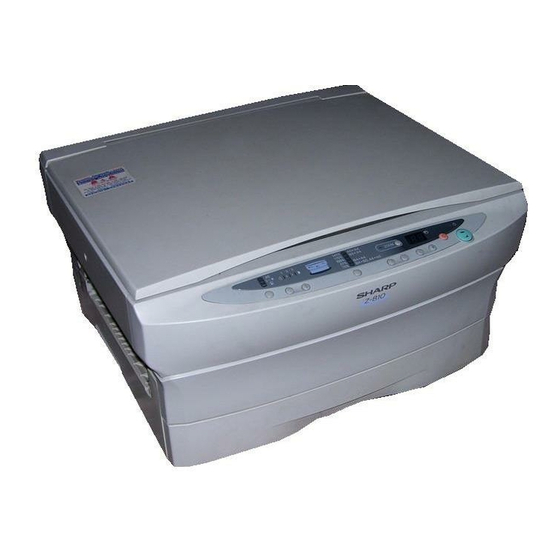
www.freeservicemanuals.info 1/11/16 [4] EXTERNAL VIEWS AND INTERNAL STRUCTURES 1. Appearance Exit tray Operation panel Document glass Document cover Power switch Paper tray Release lever Bypass tray guides Bypass tray 4 – 1 Published in Heiloo, Holland. -
Page 12: Operation Panel
1/11/16 2. Operation panel Z-810 Misfeed indicator Copy ratio Drum replacement Toner required indicator display key required indicator Copy quantity Copy ratio Power save display Exposure indicators indicators Zoom indicator indicator 141% 115% B5 A4 ZOOM 100% B4 A4... -
Page 13: Internal
www.freeservicemanuals.info 1/11/16 3. Internal Drum cartridge TD cartridge Fusing unit lever Transfer corona cleaner Fusing unit Transfer corona 4 – 3 Published in Heiloo, Holland. -
Page 14: Motors And Solenoids
www.freeservicemanuals.info 1/11/16 4. Motors and solenoids Part name Function, operation Main motor Drives the copier. Lens motor Drives the optical lens. Mirror motor Drives the optical mirror base. Toner motor Supplies toner. Cooling fan motor Cools the optical section. Exhaust fan motor Cools the inside of the machine. -
Page 15: Pwb Unit
www.freeservicemanuals.info 1/11/16 5. PWB unit Name Kind Function Output Differs depending on the Operation PWB Operation input/display — function and the destination. Differs depending on the Main PWB Copier control — function and the destination. Differs depending on the AC PWB AC power input —... -
Page 16: A Word On Copier Installation
3. Open the document cover, unfold the bypass tray, and remove all pieces of protective packing material. * Z-810 The Z-810 copier is not equipped with the bypass tray. 2. Cautions 1. Do not expose the photoconductive drum to direct sunlight, and do not touch the photoconductive drum. - Page 17 www.freeservicemanuals.info 1/11/16 4. Remove the two screws from the right and left sides of the 9. Slide the TD cartridge in until it locks in place. copier by inserting a coin or a suitable object into the slot of the 10.
-
Page 18: Copy Process
www.freeservicemanuals.info 1/11/16 [6] COPY PROCESS An OPC drum is used for the photoconductor. (Structure of the OPC drum layers) Carrier Transfer layer OPC layer (About 20µm) Carrier Generation layer Drum base 1. Copy process composition Drum cartridge TD cartridge Main charger No. -
Page 19: Image Forming Process Steps
www.freeservicemanuals.info 1/11/16 Step-3: Exposure (Copy lamp, mirror, lens) 2. Image forming process steps The original image is projected through the mirror and the lens to the Image forming: OPC drum by the copy lamp. A charge is applied to the drum surface by the main corona, and the In the area where light is projected (light section of the original), the image of the original is exposed by the copy lamp. -
Page 20: Transition Of Opc Drums Surface Potential
www.freeservicemanuals.info 1/11/16 4. Transition of OPC drum surface potential -700 -600 Charging Exposure Development Transfer Separation Cleaning Non-image Toner attract -500 area potential -400 -650V Dark area -300 OPC drum surface potential Developing bias -200 -150V -150V Developing bias -100 Light area Residual potential (-80~100V) -
Page 21: Optical System
www.freeservicemanuals.info 1/11/16 [7] OPERATION DESCRIPTIONS 7-1. Optical system • Exposure is adjusted by changing the voltage of the copy lamp. 1. General descriptions The optical unit is provided with the AE sensor for detection of the • The optical system is composed of the fixed focus lens and six original density to adjust the light quantity of the copy lamp accord- mirrors. - Page 22 www.freeservicemanuals.info 1/11/16 (7) Lens drive shaft 2. Basic operations This shaft is to control the optical axis of the lens in zoom copying. (Relationship among the original, the lens and the image in each The lens follows on the slide base shaft. magnification ratio) (8) Lens drive wire Normal copy:...
-
Page 23: Fuser Section
www.freeservicemanuals.info 1/11/16 7-2. Fuser section The mirror base scan speed (mirror motor rpm) is changed to zoom. General description The lens and the mirror are moved to zoom. Copy paper feed direction The mirror scan speed is changed to zoom. Mirror scan speed <Drum rotating speed>... - Page 24 www.freeservicemanuals.info 1/11/16 A. Heat roller D. Fusing resistor A teflon roller is used for the upper heat roller and a silicone rubber Fusing resistor roller is used for the lower heat roller for better toner fusing perfor- This model is provided with a fusing resistor in the fusing section to mance and paper separation.
-
Page 25: Paper Feed Section And Paper Transport Section
www.freeservicemanuals.info 1/11/16 7-3. Paper feed section and paper transport section Paper transport path and general operations 3 10 Paper OPC drum MG roller Resist roller Pick-up roller Transport roller Manual transport roller Manual paper feed roller Transport roller Upper heat roller Lower heat roller PPD1 sensor actuator PPD1 sensor PWB... - Page 26 www.freeservicemanuals.info 1/11/16 After 0.15sec from when the main motor start rotating, the tray To release the resist roller, the resist roller solenoid is turned on paper feed solenoid (PFS) turns on at a moment. by the paper start signal to disengage the resist start latch from the clutch sleeve projection, transmitting rotation of the resist drive This disengages the paper feed latch from the projection of the gear to the resist roller shaft.
- Page 27 www.freeservicemanuals.info 1/11/16 B. Manual multi paper feed operation When pawl C of the manual paper feed clutch sleeve is hung on the manual feed latch, the manual feed stopper falls and the Before paper feed operation, the manual paper feed solenoid manual take-up roller rises.
-
Page 28: New Drum Cartridge Detection System
www.freeservicemanuals.info 1/11/16 3. Outline of operations 7-4. New drum cartridge detection system (1) When intermittent gear A turns one rotation, the teeth of inter- mittent gear B is engaged with the teeth of intermittent gear A, 1. General rotating intermittent gear B. The position of intermittent gear B is This model employs the automatic counter clear system where the shifted from Fig.1 to Fig. -
Page 29: Disassembly And Assembly
www.freeservicemanuals.info 1/11/16 Remove five screws, and remove the PWB holder. [8] DISASSEMBLY AND ASSEMBLY 1. Operation panel 2. Optical section 3. Fusing section 4. Tray paper feed/transport section 5. Multi manual paper feed section 6. Rear frame section 1. Operation panel Remove five screws, and remove the operation PWB. - Page 30 www.freeservicemanuals.info 1/11/16 A. List Remove the copy lamp. Part name Ref. page Copy lamp unit Copy lamp AE sensor PWB Lens unit No. 2/3 mirror unit No. 4/5 mirror unit Mirror home position sensor PWB Lens home position sensor PWB B.
- Page 31 www.freeservicemanuals.info 1/11/16 Remove the mirror base drive wire, and remove No. 2/3 mirror Remove one screw, and remove the lens home position sensor. unit. Remove one screw and the spring, pull out the shaft, and remove Remove one screw, and remove the AE holder. No.
- Page 32 www.freeservicemanuals.info 1/11/16 C. Assembly procedure Basically reverse the disassembly procedure. The mirror base drive wire and the lens drive wire stretching methods are described below. a. Mirror base drive wire stretching Hook the metal fixture of the mirror base drive wire on the projec- tion of the optical base plate.
- Page 33 www.freeservicemanuals.info 1/11/16 Enlargement/Reduction: Change the position of the zooming b. Lens drive wire stretching cam to adjust. Manually move the lens carriage unit to fit the lens base edge with the center of marking on the optical base plate. Under the above state, fit zooming cam hole and drive gear hole and the optical base plate hole (by inserting a pin) and insert the zooming cam drive gear into the shaft.
-
Page 34: Fusing Section
www.freeservicemanuals.info 1/11/16 A. List Apply grease to the copy lamp unit driving section. Grease name: White grease (X5-6020) Part name Ref. page Part code: UKOG-0158FCZZ Fusing upper unit Heater lamp Copy lamp unit Thermostat unit running section Thermistor Upper heat roller Separation pawl Lower heat roller Cleaning roller... - Page 35 www.freeservicemanuals.info 1/11/16 Remove the left plate spring, and remove the heater lamp. Remove one screw and the fixing band, and remove the thermis- tor. Plate spring Heater lamp Remove the spring, and the separation pawl. Remove two screws, and remove the thermostat. Separation pawl Remove the plate spring of the heater lamp on the right side.
-
Page 36: Tray Paper Feed/Transport Section
www.freeservicemanuals.info 1/11/16 Remove C-ring on the right side, and remove the gear and the Remove the cleaning roller. bearing. C-ring Bearing Cleaning roller C. Assembly procedure Upper heat roller Gear Reverse the disassembly procedure. C-ring D. Lubrication and greasing Bearing Apply grease to the U section of the lower heat roller bearing. - Page 37 www.freeservicemanuals.info 1/11/16 A. List Remove PPD1 sensor PWB. Part name Ref. page Paper feed roller ass’y PPD1 sensor PWB PPD2 sensor PWB B. Disassembly procedure Remove three screws and the harness, and remove the tray paper feed unit (paper transport unit). PPD1 Tray paper feed unit sensor...
-
Page 38: Manual Paper Feed Section
www.freeservicemanuals.info 1/11/16 C. Assembly procedure Remove two screws and the spring, and remove the arm hinge, arm B, stopper, and arm A. Reverse the disassembly procedure. 5. Manual paper feed section * Descriptions are based on the multi manual paper feed unit. Arm B Stopper Arm A... - Page 39 www.freeservicemanuals.info 1/11/16 Remove the parts as shown below. Remove the parts of spring clutch A as shown below. Remove the paper feed roller. Remove two screws, and remove the bracket. Paper feed roller Remove the pick-up roller. Pick-up roller 8 – 11 Published in Heiloo, Holland.
- Page 40 www.freeservicemanuals.info 1/11/16 Remove the parts of spring clutch B as shown below. Be careful of the insertion position of the spring when installing spring clutch B. Remove one screw, and remove the multi field solenoid. * Insert the hook into the initial position where it was before disassembly.
-
Page 41: Rear Frame Section
www.freeservicemanuals.info 1/11/16 Apply grease to the engagement section of the pick-up roller. 6. Rear frame section Grease name: Floil grease (Floil G-484) Part code: UKOG-0238FCZZ Apply grease to the gearing of arm C. A. List Grease name: Floil grease (Floil G-484) Part name Ref. - Page 42 www.freeservicemanuals.info 1/11/16 Remove two screws and the harness, and remove the DC PWB Remove four screws, and remove the cover. unit. Remove two screws and the harness, and remove the AC PWB Remove one screw and the harness, and remove the high voltage unit.
-
Page 43: Others
www.freeservicemanuals.info 1/11/16 Remove three screws, and remove the socket unit. 7. Others Remove the five screws and the harness, and remove the drive unit. A. OC matt attachment procedure Put the OC matt to the reference position as shown below and remove the duplex tape. -
Page 44: Adjustments
www.freeservicemanuals.info 1/11/16 [9] ADJUSTMENTS 1. Optical section A. Adjustments list Adjustment value/ Necessary Ref. Classification Adjustment content Standard value special tool page Parts installation (1) Mirror a No. 4/5 mirror unit right angle adjustment — — position b No. 4/5 mirror unit drive cam position adjustment —... - Page 45 www.freeservicemanuals.info 1/11/16 (2)-a Use the test chart Make a test chart. (Draw a (UKOG-0089CSZZ) or the resolution rectangular on A4 or chart, andmake a 100% copy on A4 8 1/2" x 11"paper.) or 8 1/2" x 11" paper so that the resolutionpatterns are copied at the center and the four corners.
- Page 46 www.freeservicemanuals.info 1/11/16 Make copies at the max. Use a half tone document, and the min. ratios. and make a 100% copy on A4 or 8 1/2" x11" paper. Measure the distance between the copy image lead edge and the copypaper lead edge of each Check the uniformity.
- Page 47 www.freeservicemanuals.info 1/11/16 C. Adjustment contents 2) Remove the optical unit cover. (1) Mirror The following are adjustment items of the mirror unit. * No. 4/5 mirror unit right angle adjustment * No. 4/5 mirror unit drive cam position adjustment a. No. 4/5 mirror unit right angle adjustment I.
- Page 48 www.freeservicemanuals.info 1/11/16 5) Loosen the No 4/5 mirror unit drive can fixing screw without b. No. 4/5 mirror unit drive cam position adjustment moving the lens unit drive gear. I. Summary The copy magnification ratio and focus are properly adjusted by matching the lens unit movement and the No.
- Page 49 www.freeservicemanuals.info 1/11/16 Install the No. 1 and No. 2 scanner units to the specified posi- 3) Loosen the fixing screw of the copy lamp unit wire. tions, adjust the mechanical horizontal parallelism, and perform the final adjustment while making copies. II.
- Page 50 www.freeservicemanuals.info 1/11/16 5) Loosen the copy lamp unit/No.2/3 mirror unit drive pulley Procedures 1) to 8) are for adjustment of mechanical horizontal setscrew in the side where No.2/3 mirror unit does not make parallelism. The copy lamp unit and No.2/3 mirror are fixed to contact with No.2/3 mirror unit positioning plate.
- Page 51 www.freeservicemanuals.info 1/11/16 12) Without moving the copy lamp unit/No.2/3 mirror unit drive V. Necessary tools pulley shaft, manually turn the copy lamp unit/No.2/3 mirror * Screwdriver (+) unit drive pulley whose setscrew was loosened, and adjust * Screwdriver (–) the parallelism of copy lamp unit/No.2/3 mirror unit. * Scale No.
- Page 52 www.freeservicemanuals.info 1/11/16 4) Change the height of the roller in No.4/5 mirror unit front IV. Cases when the adjustment is required frame side to adjust the vertical image distortion. 1) When the lens unit is disassembled or its part is replaced. If the copy image is tilting as shown in sample (X) below, 2) When the copy image is shifted from the vertical center of lower No.4/5 mirror unit.
- Page 53 www.freeservicemanuals.info 1/11/16 7) Remove the optical unit cover. 2) When the copy lamp unit/No.2/3 mirror unit drive section is disassembled or its part is replaced. 3) When a cop image of improper focus is obtained. V. Necessary tools * Screwdriver (+) * Test chart (One with the resolution adjustment chart) VI.
- Page 54 www.freeservicemanuals.info 1/11/16 advance to the horizontal copy magnification ratio adjustment. 7) Loosen the fixing screw of No.4/5 mirror unit drive lever to Never reverse the sequence. (The horizontal copy magnification change the position of No.4/5 mirror unit drive lever or No.4/5 ratio is based on the vertical copy magnification ratio.) mirror unit.
- Page 55 www.freeservicemanuals.info 1/11/16 (When a 100mm scale is used as the original.) Original (Scale) HARDDENCD STAINLESS JAPAN 1/2mm Shizuoka HARDDENCD STAINLESS JAPAN Paper feed direction 1/2mm Shizuoka Reference Comparison point Copy 5) Calculate the vertical copy magnification ratio. b. Horizontal copy magnification ratio adjustment (Zoom Copy image size copy) Vertical copy magnification ratio =...
- Page 56 www.freeservicemanuals.info 1/11/16 V. Adjustment procedure 1) Set the scale on the document table as shown below. (Use a long scale for precise adjustment.) 2) Set the copy magnification ratio to 100%. ⁄ 3) Make a copy on A4 or 8 "...
- Page 57 www.freeservicemanuals.info 1/11/16 Repeat procedures 1) to 8) until the horizontal copy magnifica- Exposure adjustment plate tion ratio in the normal (100%) copy mode is within the specified range. (6) Uniformity adjustment I. Summary The uniformity adjustment is performed by changing the ex- posure plate position attached to No.1 scanner unit.
- Page 58 www.freeservicemanuals.info 1/11/16 III. Note When the set value is made greater, the copy image posi- tion for the copy paper moves backward. When the set If the proper void area is not obtained, the separation ability in value is made greater, the copy image position for the copy the photoconductor section may be degraded and dirt on the paper moves forward.
- Page 59 www.freeservicemanuals.info 1/11/16 Scale image lead edge Scale image lead edge Reduction copy (x 0.70) Reduction copy (x 0.70) 5) Enter the measure values in procedure 4) into the formula 10) Make a 100% copy, and check that the copy image lead edge is in the range of 0.5 ±1.0 mm from the paper lead below to calculate adjustment value A and adjustment value B.
- Page 60 www.freeservicemanuals.info 1/11/16 II. Purpose Void area The purpose od this adjustment is to improve separation in the photoconductor section and in the fuser section and reduce dirt on the fuser section pawl by obtaining the max. effective copy area and the proper void area. III.
-
Page 61: Copy Density Adjustment
When the set value is made greater, the void area be- * A4 (8 1/2" x 11") white paper comes greater, and vise versa. Test chart comparison UKOG-0162FCZZ DENSITY No. UKOG-0089CSZZ DENSITY No. KODAK GRAY SCALE SHARP CORPORATION MADE IN JAPAN 9 – 18 Published in Heiloo, Holland. - Page 62 Sim 46-01. The exposure level is changed by changing the copy lamp voltage. Check that "5" of the exposure test chart (SHARP GRAY CHART) is slightly copied. The copy density adjustment must be performed for five copy modes.
- Page 63 (4) Make a copy. (2) Adjust at exposure level 3, 1, and 5 similarly with the manual Check that "7" of the exposure test chart (SHARP GRAY mode (non-toner save mode). CHART) is slightly copied. E. Auto copy mode (Non-toner save mode) copy density...
- Page 64 www.freeservicemanuals.info 1/11/16 (6) Copy density adjustment table Copy mode Mode display Exposure level Test chart copy density Slightly copied. Not copied. Non-toner save Manual mode Slightly copied. Not copied. Clearly copied. Not copied. Manual Slightly copied. Not copied. Toner save mode Manual/Photo Slightly copied.
-
Page 65: Others
www.freeservicemanuals.info 1/11/16 Copy mode Mode display Exposure level Test chart copy density Slightly copied. Not copied. Photo — Photo Clearly copied. Not copied. Check that "10" is displayed on the copy quantity display. Non-toner save Auto Auto mode Slightly copied. Not copied. - Page 66 www.freeservicemanuals.info 1/11/16 5) Pull out the tray, and loosen the off center adjustment screw. Adjust the DV bias adjustment volume to set the output voltage to –150±10V. R207 6) Slide the off center adjustment screw back and forth. (3) Main charger Set the digital multi meter range to DC700V or above.
-
Page 67: Entering The Simulation Mode
www.freeservicemanuals.info 1/11/16 [10] SIMULATION LIST 1. Entering the simulation mode Press the clear key → the exposure mode selector key → the clear key → the exposure mode selector key inthis sequence to enter the serviceman simulation mode. Press the clear key to cancel the simulation mode. -
Page 68: Simulation List
www.freeservicemanuals.info 1/11/16 2. Simulation list Main code Sub code Content Mirror base operation check, optical system sensor status display Optical system sensor status display Lens, No. 4/5 mirror operation check Lens, No. 4/5 mirror aging Operation panel display check Heater lamp check Copy lamp check Discharge lamp check Blank lamp check... -
Page 69: Contents Of Simulations
www.freeservicemanuals.info 1/11/16 3. Contents of simulations Main code Sub code Content Scanner unit and its control circuit operation check (Operation/procedure) 1. Execute this simulation to detect the mirror and the lens home positions. Sensor name Display lamp Mirror home position sensor (MHPS) : Drum replacement required indicator Lens home position sensor (LHPS) : Toner required indicator... - Page 70 www.freeservicemanuals.info 1/11/16 Main code Sub code Content Main charger, transfer charger voltage check (Phot copy mode) (Operation/procedure) The main charger and the transfer charger are turned on for 30 sec in the photo copy mode. Check that the output is –400±10V. If not, adjust. Main charger, transfer charger voltage check (Toner save mode) (Operation/procedure) The main charger and the transfer charger are turned on for 30 sec in the toner save copy mode.
- Page 71 100 V Auto density lamp 120 V Auto/Manual density lamp 200 V Auto/Manual/Photo density lamp Version Lighting lamp SHARP None JAM lamp ON Copy speed COPIES MADE display (CPM) 8 CPM 10 CPM Exposure adjustment value setting for OPC drum membrane decrease correction...
- Page 72 www.freeservicemanuals.info 1/11/16 Main code Sub code Content Fusing temperature setting (Operation/procedure) When this simulation is executed, the currently set temperature (the code number) is displayed. Enter the code number corresponding to the desired temperature and press the COPY key to set it. Code No.
- Page 73 www.freeservicemanuals.info 1/11/16 Main code Sub code Content Copy density adjustment mode Copy density level Copy mode Lighting lamp (Exposure level) None-toner-save mode Manual density lamp Manual copy mode Toner save mode Manual/Photo density lamp None-toner-save mode Auto density lamp 1 (*3) Auto copy mode Toner save mode Auto/Photo density lamp...
- Page 74 www.freeservicemanuals.info 1/11/16 Main code Sub code Content Copy paper image position adjustment (Operation/procedure) When this simulation is executed, the machine performs warm-up and the currently set value is displayed on the COPY QUANTITY display. There are two sets of set values (A, B). Every time when the density select key is pressed, the set density is switched.
-
Page 75: Toner Save Mode Setting And Cancel
www.freeservicemanuals.info 1/11/16 4. Toner save mode setting and cancel Use the density select key to set to "Manual" and keep pressing the density key again for 5 sec, and the mode display will change from "Manual" to "Photo" (blinking) and the currently set level is displayed on the exposure level display. - Page 76 www.freeservicemanuals.info 1/11/16 4. Select the desired parameter using the right copy [11] USER PROGRAMS quantity ( ) key. The user programs allow the parameters of certain functions to be set, changed, or cancelled as desired. 1. Press and hold the light ( ) and dark ( ) keys simultaneously for more than 5 seconds until all the...
- Page 77 www.freeservicemanuals.info 1/11/16 Copy count remaining for drum cartridge replacement To find out how many more copies can be made before the 12,000 mark is reached, follow the procedure described below. 1. Press and hold the light ( ) and dark ( ) keys simultaneously for more than 5 seconds until all the trouble indicators...
-
Page 78: Block Diagram
www.freeservicemanuals.info 1/11/16 [12] ELECTRICAL SECTION 1. Block diagram A. Overall block diagram Operation PWB Lens Mirror motor LHPS AE sensor motor MHPS CFM1 CFM2 MAIN PWB CPU,I/O,MEMORY,DRIVER MPFS MMRE Toner MAIN High voltage MOTOR motor Interlock Copy lamp switch MAIN SWITCH DC power AC PWB... -
Page 79: Circuit Descriptions
www.freeservicemanuals.info 1/11/16 2. Circuit descriptions A. Main PWB (1) CPU (IC101) TMP90CM38F (TMP90PM38F) General The TMP90CM38F is a high-performance 8-bit micro-controller developed for use in control of various devices. In the TMP90CM38F, the 8-bit CPU, ROM, RAM, the A/D convertor, the multi-function timer, the event counter, the general-purpose serial interface, the pattern generation, the stepping motor controller are integrated into one chip. - Page 80 www.freeservicemanuals.info 1/11/16 ALE(P83) RESET 32KB TLCS-90 P00~P07 (P82)STBY Port 0 (A/D0~A/D7) Internal bus P10~P17 Port 1 (A8~A15) AGND VREF 8bit A/D Converter Port 2 P20~P23 AN0-AN7 Port 3 P30~P33 RXD1 Serial I/O (UART + I/O) SCLK1/CTS1 Watch TXD1 Port 4 P40~P47 RXD2 Timer...
-
Page 81: Cpu Signal Table
www.freeservicemanuals.info 1/11/16 CPU signal table CPU TMP90CM38F (TMP90PM38F) Pin No. Pin name Input/Output Signal code Specifications Logic P57 (TO3) Output Heater lamp — Interruption request input Zero-cross signal — P100 Output Toner supply motor a — P101 Output Toner supply motor b —... - Page 82 www.freeservicemanuals.info 1/11/16 (2) Serial/parallel conversion IC (IC204) NJU3713G Pin No. 12BIT Serial-parallel load General PORT1 Blank lamp 0 The NJU3713 is a serial/parallel conversion IC which converts 12-bit serial data into parallel data, and serves as an output port extension PORT2 Blank lamp 1 device of the CPU.
- Page 83 www.freeservicemanuals.info 1/11/16 (4) Heater lamp control circuit 1. General The heater lamp control circuit detects the heat roller surface temperature from the thermistor, and converts it into a voltage level, which is delivered to the CPU analog input pin. The CPU converts the analog voltage into a digital signal level, com- pares it with the set value of simulation, and turn on/off the heater lamp depending on the level, maintaining the heat roller surface temperature at a constant level.
- Page 84 www.freeservicemanuals.info 1/11/16 Stepping motor drive circuit (5) Driver circuit (Solenoid) 1. General 1. General This driver circuit drives the lens drive motor. It is impossible for the control signal of each load from the CPU to directly drive the load. The control signal is passed through the driver A: Stepping motor phase A coil drive signal IC then to each load.
- Page 85 www.freeservicemanuals.info 1/11/16 (8) Toner supply motor drive circuit 2. Operation • The IC103 controls the toner supply motor. Pseudo-AC waveforms After turning on the power, and after td (30msec) time from when are produced from the pulse signals (TMa, TMb) from the CPU to the voltage exceeds 4.25V, the output becomes HIGH.
- Page 86 www.freeservicemanuals.info 1/11/16 (10) Copy lamp control section The output of transformer T301 in the AC PWB described later is monitored by the CPU to detect the variation in the AC power voltage, controlling the phase of copy lamp applying voltage and maintaining the voltage at a constant level.
- Page 87 www.freeservicemanuals.info 1/11/16 60Hz 50Hz (msec) Pulse ON time CPU output (CLPWM) • The shorter the pulse ON time is, the higher the CLV is, and vice versa. • The pulse ON time rises at the zero-cross timing of AC and is driven with duty.
- Page 88 www.freeservicemanuals.info 1/11/16 (12) Main motor drive circuit The encoder signal for the main motor is inputted to the CPU, where operation process is performed. Then the CPU delivers the PWM signal to control the main motor. The PWM signal (MM-PWM) from the CPU is applied to the gate of FETQ103 through the driver IC104 and transistor Q214, flowing a current through the main motor.
-
Page 89: B. Operation Panel Section
www.freeservicemanuals.info 1/11/16 B. Operation panel section (2) Display circuit section This circuit is controlled by the data signal and the control signal from (1) General the main control signal. The operation circuit is composed of the display matrix circuit and the <Block diagram>... - Page 90 www.freeservicemanuals.info 1/11/16 (2) AC input section (filter, etc.) (5) Hybrid IC (IC802) pin functions The input filter is of LC filter in one-step composition, and reduces The figure below shows the block diagram of hybrid IC (IC802). common mode noises and normal mode noises from the AC line. The STR-F6515 block diagram across-the-line capacitor, the line bypass capacitor, and the common mode choke coil are provided on the AC PWB.
- Page 91 www.freeservicemanuals.info 1/11/16 When the output voltage falls below the specified level under overload state, the voltage in the additional winding of the primary side also falls accordingly to fall the VIN pin voltage below the operation start voltage. Therefore, the VIN pin voltage rises again and starts operation at the operation start voltage, performing intermittent operations.
-
Page 92: A. Main Pwb Circuit
www.freeservicemanuals.info 1/11/16 3. CIRCUIT DIAGRAM A. MAIN PWB CIRCUIT .............12-15 B. OPERATION PWB CIRCUIT..........12-22 C. DL PWB CIRCUIT ..............12-25 D. BL PWB CIRCUIT..............12-26 E. SENSOR PWB A/B..............12-27 F. SENSOR PWB C..............12-28 G. AC POWER SUPPLY CIRCUIT ..........12-29 H. DC POWER SUPPLY CIRCUIT ..........12-35 4. - Page 93 1/11/16 COPYRIGHT 1996 BY SHARP CORPORATION All rights reserved. Printed in Japan. No part of this publication may be reproduced, stored in a retrieval system, or transmitted, in any form or by any means, electronic, mechanical, photocopying, recording, or otherwise, without prior written permission of the publisher.
Need help?
Do you have a question about the Z-810 and is the answer not in the manual?
Questions and answers