Table of Contents
Advertisement
Quick Links
- 1 Table of Contents
- 2 Specifications
- 3 Model Designation of the Head Section
- 4 Timing between the Needle and the Hook
- 5 List of Selective Combination Parts and Maintenance Parts
- 6 Optional Parts
- 7 Troubles in Sewing and Corrective Measures
- 8 Table Dimension Diagram
- Download this manual
See also:
Instruction Manual
Advertisement
Table of Contents

Related Manuals for JUKI DU-1181


Summary of Contents for JUKI DU-1181
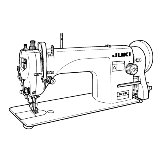
- Page 1 ® 1-NEEDLE, TOP AND BOTTOM FEED LOCKSTITCH MACHINE WITH A LARGE HOOK DU-1181 DU-1181N ENGINEER’S MANUAL 40040471 No.E371-00...
- Page 2 Introduction This Engineer’s Manual is for technical service engineers. In the instruction manual for the maintenance engi- neers of sewing machines and sewing workers in a sewing factory, how to operate a sewing machine is also described in detail. However, in this manual, [Adjustment Procedure], [Results of Value Change for Adjustment], and the roles of each component are described: these are not included in the instruction manual.
-
Page 3: Table Of Contents
CONTENTS 1. Specifications ......................1 2. Model Designation of the Head Section ..............2 (1) DU-1181 ............................2 (2) DU-1181N ........................... 2 3. Standard Adjustment ....................3 (1) Height of Needle Bar ......................... 3 (2) Timing between the Needle and the Hook ................3 (3) Lengthwise Position of Bobbin Case Positioning Finger ............. -
Page 4: Specifications
Automatic lubrication (Manual lubrication only for top feed section) Oil Return Flow Circulated with plunger pump Lubricating Oil JUKI Machine Oil No. 7 (equivalent to ISO VG7) Grease JUKI Grease A (White) Tube of 10g grease (Part No. : 40006323), or 500g can (P/art No. -
Page 5: Model Designation Of The Head Section
2. Model Designation of the Head Section (1) DU-1181 Name: 1-Needle, Top and Bottom Feed Lockstitch Machine with a Large Hook D U 1 1 8 1 – Specification Code for Destination Accessory Specification Code Standard (WEEE compatible) Standard CE compatibel China (within China) U.S.A. -
Page 6: Standard Adjustment
3. Standard Adjustment (1) Height of Needle Bar Standard Adjustment Requirement: • The needle bar should be brought to the lowest dead point. Marker Lines engraved in the Needle Bar (for DP x 17): (Standard) Marker Lines engraved in the Needle Bar (for DB x 1): (2) Timing between the Needle and the Hook Standard Adjustment 1) Needle Lifting Amount and Positions of the... - Page 7 Adjustment Procedure Results of Improper Adjustment o Stitch skipping or thread breakage 1. Turn the hand-wheel to bring the needle bar to the lowest dead point. may be caused. 2. Loosen the clamping screw of the needle bar connecting bracket 3.
-
Page 8: Lengthwise Position Of Bobbin Case Positioning Finger
(3) Lengthwise Position of Bobbin Case Positioning Finger Standard Adjustment Requirements: • The needle entry should be within a range between the center of the bobbin case positioning finger projection and the shoulder section. • The needle bar should be brought to the lowest dead point. - Page 9 Adjustment Procedure Results of Improper Adjustment o Thread tension failure may be 1. Turn the hand-wheel to bring the needle bar to the lowest dead point. caused. 2. Loosen the set screw of the bobbin case positioning finger 3. Move the bobbin case positioning finger in the arrow direction so that the needle entry is within the range between the center of the projection on the bobbin case positioning finger...
-
Page 10: Feeding Alignment
(5) Feeding Alignment Standard Adjustment Later Earlier Hand-wheel side Requirements: First or second • Feed Level: Maximum (9 mm) tooth • Just when the first or second tooth at the front end of the feed dog is lowered from the upper surface of the throat plate, the center of the needle hole should come in contact with the upper surface of the throat plate. - Page 11 Adjustment Procedure Results of Improper Adjustment Feed Driving Cam Feed Driving Cam If the feed driving timing is earlier: 1. Set the stitch dial to 9 mm on the scale. o Isolated idling loops will be improved, but the thread tension 2.
-
Page 12: Upper Feed Motion
(7) Upper Feed Motion Standard Adjustment 1) Outer Presser Foot Position Requirements: • Feed Level: Maximum (9 mm) • A clearance of 2.4 mm should be provided between the outer presser foot and inner presser foot when the outer presser foot and the inner presser foot are rested on the throat plate and the outer presser... - Page 13 Adjustment Procedure Results of Improper Adjustment o If the position is set incorrectly, top 1) Position Adjustment for the Outer Presser Foot feed components may come in 1. Set the stitch dial to 9 mm on the scale. contact each other, which results in abnormal noise.
-
Page 14: Upper Feed Differential
(8) Upper Feed Differential Standard Adjustment Top feed Standard: • Attach the slide block assembly through the long eccentric hole so that the distance between the cen- ter of the upper feed driving shaft and the center of the slide block assembly bolt becomes 25.5 ±... - Page 15 Adjustment Procedure Results of Improper Adjustment If it is set to the upper position: 1. Lift the presser bar lifter. The upper cloth is insuffi- 2. Loosen the slide block nut using a spanner of 11 mm. ciently fed, so will be curved 3.
-
Page 16: Stitch Length In Forward And Reverse Feed
(10) Stitch Length in Forward and Reverse Feed Standard Adjustment Requirements: • Feed Level : 9 mm • When the hand-wheel is turned by hand and a cloth is sewn 10 stitches in both for- ward and reverse feed stitching the differ- ence in stitch length should be 2 mm or less. - Page 17 Adjustment Procedure Results of Improper Adjustment o The stitch length in the normal 1. Set the stitch dial to 9 mm on the scale. feed stitching may differ from that 2. Loosen the set screw of the pin on the feed regulator base in the reverse feed stitching.
-
Page 18: Lubrication
(12) Lubrication Standard Adjustment 1) Face Section Oil Level Adjustment Fig. 1 Maximum Minimum <Adequate range of the face section oil level> Splashed oil (little) Requirements: 2000rpm Oil Level (Trace) Splashed oil (Much) <Adequate range of the hook oil level> Splashed oil 2) Hook Oil Level Adjustment (little) - Page 19 Adjustment Procedure Results of Improper Adjustment 1) Face Section Oil Level Adjustment 1. Loosen the set screw of the oil preventive plate and remove the oil preventive plate 2. For adjustment of the oil level for the thread take-up lever and needle bar crank section , turn the oil level adjusting pin 3.
-
Page 20: Grease Application
4. Grease Application The lubricating locations in component assembling work are as follows. o If any component disassembling work is performed, apply JUKI Grease A (a tube of 10g white grease: P/N 40006323) or 500g can (P/N 23640204) onto the specified locations. - Page 21 o Upper Feed Mechanism Components ∗ ∗ ∗ ∗ ∗ ∗ ∗ ∗ ∗ ∗ ∗ ∗ ∗ ∗ ∗ ∗ ∗ – 18 –...
-
Page 22: List Of Selective Combination Parts And Maintenance Parts
5. List of Selective Combination Parts and Maintenance Parts Selective Combination Parts Selective Combination Part Name Part No. Remarks L-plate Rod Presser Washer A 40029413 Standard (t = 2.1 –0.02 L-plate Rod Presser Washer B 40029414 Selective (t = 2.05 –0.02 L-plate Rod Presser Washer C 40029415... -
Page 23: Optional Parts
6. Optional Parts No. Note Part No. Part Name Remarks B1524141HAB Movable Walking Foot B1525141H0 Movable Presser Foot B1526141H0A Fixed Walking Foot B1526141H00 Fixed Presser Foot B1527141H0 Grooved Walking Foot Cord Piping B1527141H00 Grooved Presser Foot B1528141H0 Back-cut Grooved Walking Foot For cord piping (Curve) B1527141H00 Back-cut Grooved Presser Foot... -
Page 27: Table Dimension Diagram
2 x ø3.5, Depth: 4 12±1 (72.2) 339.7±1 68.1±0.5 (21) Logo type designated by JUKI (525) (591) 2 x ø3.4 Depth at the rear side: 10 (Drill a hole at the time of set-up). Y-Y Section Rubber Installation Reference Figure 1.2±0.5 V-V (1:1) ø26... - Page 28 MEMO...
- Page 29 Please do not hesitate to contact our distributors or agents in your area for further information when necessary. * The description covered in this engineer's manual is subject to change for improvement of the Copyright © 2005 JUKI CORPORATION. commodity without notice.
Need help?
Do you have a question about the DU-1181 and is the answer not in the manual?
Questions and answers
What are the juki Machines prefixes tell us?