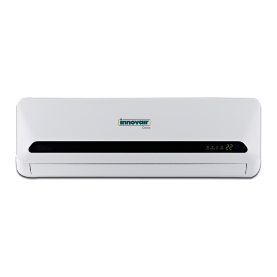
Summary of Contents for innovair Oasis WOE10C2DB1 / HOE10C2MR83
-
Page 1: Installation Manual
Oasis INSTALLATION MANUAL WOE10C2DB1 / HOE10C2MR83 WOE13C2DB1 / HOE13C2MR83 WOE18C2DB1 / HOE18C2MR83 WOE24C2DB1 / HOE24C2MR83 WOE36C2DB1 / HOE10C2MR1 MINI SPLIT SYSTEM ©2015 Innovair Corporation. All Rights Reserved. www.innovair.com... -
Page 2: Table Of Contents
If the power cord is to be replaced, replacement work shall be performed by authorized personnel only. • Installation work must be performed in accordance with the national wiring standards by authorized personnel only. ©2015 Innovair Corporation. All Rights Reserved. www.innovair.com... -
Page 3: Safety Precautions
Carry out drainage piping as mentioned in installation instructions. If drainage is not perfect, water may enter the room and damage the furniture. ©2015 Innovair Corporation. All Rights Reserved. www.innovair.com... -
Page 4: Selecting Installation Place
Fig.12 nameplate before selecting the cable, fuse and switch. ©2015 Innovair Corporation. All Rights Reserved. www.innovair.com For more details visit www.MrCool.com For more details visit www.MrCool.com For more details visit www.MrCool.com For more details visit www.MrCool.com... -
Page 5: Accessories
• This illust ration is for explanation purposes only. • Copper lines must be insulated independently. Quick connecting refrigerant pipe Remote Controller Mounting screw B ST2.9x10-C-H Remote controller holder Fig.3 ©2015 Innovair Corporation. All Rights Reserved. www.innovair.com... -
Page 6: Indoor Unit Installation
Pipe hole 1030/40.55 <!>90/3.54in 22000Btu/h models n 150mm/5.91 in or more to ceiling 1450/57.09 --------------------------�- r-;l;tl:!:lt.l=,,��"""'���lltij�"""',=c����t:ll::tt.l=,,1-_J� 120mm/4.72in I or more to wall Left rear side refrigerant Pipe hole <!> 90/3.54in >30000Btu/h models Fig.5 ©2015 Innovair Corporation. All Rights Reserved. www.innovair.com... - Page 7 Improper handling of refrigerant may be harmful during connection. to health. Always wear work gloves and goggles when handling refrigerant. ©2015 Innovair Corporation. All Rights Reserved. www.innovair.com...
- Page 8 See Fig.12. NOTE: For aesthetic reasons, the quick connector parts • are recommended to be placed outside of room. Fig.12 ©2015 Innovair Corporation. All Rights Reserved. www.innovair.com...
- Page 9 Get it out after finish piping. 4. Press the lower left and right sides of the unit Fig.15 against the installation plate until the hooks engage into their slots. ©2015 Innovair Corporation. All Rights Reserved. www.innovair.com...
-
Page 10: Outdoor Unit Installation
��rain pipe fixed with a clicking sound. Connecting the drain joint with an extension drain hose (Locally Fig.19 purchased), in case of the water draining off the outdoor unit during the heating mode. ©2015 Innovair Corporation. All Rights Reserved. www.innovair.com... -
Page 11: Refrigerant Pipe Connection
See the next page for the proper torque. Fig.22 IMPORTANT: Since the coupling works with tapping rings, it may leak if you undo and reconnect the pipes. This will void the warranty. Fig.23 ©2015 Innovair Corporation. All Rights Reserved. www.innovair.com... -
Page 12: Refrigerant Pipe Connection
If any bubbles form, the system has a leak and the screw connectors must be retightened using an open-ended wrench. Fig.25 ©2015 Innovair Corporation. All Rights Reserved. www.innovair.com... -
Page 13: Electrical Work
ELECTRICAL WORK Condenser Connection Connection at the condesnser slides over the spade. Air Handler Connection Air handler preconnected at factory, no connection Grounding Wire needed. Use screw to connect to ground. ©2015 Innovair Corporation. All Rights Reserved. www.innovair.com... -
Page 14: Test Running
Fig.28 repair, maintenance or installation of this unit. Fig.12 nameplate before selecting the cable, fuse and switch. ©2015 Innovair Corporation. All Rights Reserved. www.innovair.com For more details visit www.MrCool.com For more details visit www.MrCool.com For more details visit www.MrCool.com For more details visit www.MrCool.com... -
Page 15: Troubleshooting
The cable size and the current of the fuse or switch are determined by the rnaxirnurn current indicated on the nameplate which located on the side panel of the unit. Please refer to the nameplate before selecting the cable, fuse and switch. ©2015 Innovair Corporation. All Rights Reserved. www.innovair.com... - Page 16 5. Insulate unused cords (conductors) with PVC-tape. Process them so they do not touch any electrical or To ou� uni t To ou � r uni t metal parts. Model B Screw ©2015 Innovair Corporation. All Rights Reserved. www.innovair.com...
- Page 17 Innovair Corporation 11490 NW 39 Street Miami, FL 33178 www.innovair.com ©2015 Innovair Corporation. All Rights Reserved. www.innovair.com...


Need help?
Do you have a question about the Oasis WOE10C2DB1 / HOE10C2MR83 and is the answer not in the manual?
Questions and answers