Table of Contents
Advertisement
Quick Links
CONTENTS
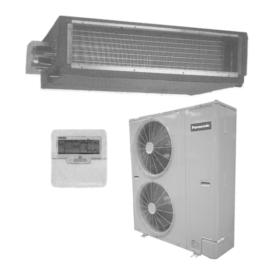
CS-W50BD3P CU-V50BBP8
CS-W50BD3P CU-W50BBP8
Page
2
3
9
10
11
13
22
24
25
26
28
29
30
31
© 2002 Matsushita Industrial Corporation. Sdn. Bhd.
(11969-T). All rights reserved. Unauthorized copying
and distribution is a violation of law.
ORDER NO. MAC0210060C2
AIR CONDITIONER
Page
33
34
35
37
42
43
47
48
49
55
56
66
78
90
Advertisement
Table of Contents

Related Manuals for Panasonic CS-W50BD3P


Summary of Contents for Panasonic CS-W50BD3P
-
Page 1: Table Of Contents
ORDER NO. MAC0210060C2 AIR CONDITIONER CS-W50BD3P CU-V50BBP8 CS-W50BD3P CU-W50BBP8 CONTENTS Page Page 1 SERVICE INFORMATION 15 CAPACITY AND POWER CONSUMPTION 2 FEATURES 16 DISCHARGE AND SUCTION PRESSURE 3 SPECIFICATION (HEAT PUMP TYPE) 17 SOUND DATA 4 SPECIFICATION (COOLING ONLY TYPE) -
Page 2: Service Information
1 SERVICE INFORMATION Caution: Pb free solder has a higher melting point than standard solder; Typically the melting point is 50 - 70°F (30 - 40°C) higher. Please use a high temperature soldering iron. In case of the soldering iron with temperature control, please set it to 700 ± 20°F (370 ± 10°C). Pb free solder will tend to splash when heated too high (about 1100°... -
Page 3: Features
2 FEATURES 2.1. Variety of excellent features 2.1.5. Quiet operation • • • • The sound level is as low as 40dB (A) for 6HP. The models 2.1.1. Compact design, height 27 cm is ideal for installation in offices, shop and houses where •... - Page 4 2.2. New low-noise outdoor units [Product features] 2. The adoption of double-orifice rings reduces air passage resistance. 2.2.1. Low-noise design improves in 3. Strengthening of the noise insulation materials in the surrounding areas compressor and the sealing-in of mechanical noise allows vibration noise to be greatly enclosed and suppressed.
-
Page 5: Additional Refrigerant Charging
2.3. Greatly improved workability increases system renewal capability 2.3.1. Pipes that are one size larger can also be connected for renewal • • • • If renewing the system, existing refrigerant pipes can be utilized so that only the indoor units and outdoor units need to be replaced. -
Page 6: Group Control Equipment
2.3.8. Centralized draining method wires and signal wires. If a connection error is made, the relay does not operate and current does not flow to the • • • • Even when multiple outdoor units are installed to a wall, the circuit boards. -
Page 7: Pipe Installation
Twin combination table Refrigerant pipe storing Location Installation period Storing method Outdoors 1 month or more Pinching Less than 1 month Pinching or taping Indoors • • • • Pinching method Close off the ends of the pipes with pliers or similar tool and seal the opening by brazing. - Page 8 11. Air-tightness test. (It is recommended that a manifold with sight glass be used.) For the final check, there should be no pressure drop when 3.3 MPa is applied for 24 hours. 12. Vacuum drying. Boiling point at normal atmospheric pressure (reference) Vacuum draw time 60 min.
-
Page 9: Specification (Heat Pump Type)
3 SPECIFICATION (HEAT PUMP TYPE) CS-W50BD3P / CU-W50BBP8 ITEM / MODEL Indoor Unit Outdoor unit Main Body CS-W50BD3P CU-W50BBP8 Cooling Capacity 14.00 (BTU/h) (47,700) Heating Capacity 16.00 (BTU/h) (54,600) Refrigerant Charge-less Standard Air Volume for High Speed /min Hi 40... -
Page 10: Specification (Cooling Only Type)
4 SPECIFICATION (COOLING ONLY TYPE) CS-W50BD3P / CU-V50BBP8 ITEM / MODEL Indoor Unit Outdoor unit Main Body CS-W50BD3P CU-V50BBP8 Cooling Capacity 14.00 (BTU/h) (47,700) Refrigerant Charge-less Standard Air Volume for High Speed /min Hi 40 Hi 1413 External Static Pressure... -
Page 11: Technical Drawing
5 TECHNICAL DRAWING CS-W50BD3P OUTSIDE DIMENSIONS... - Page 12 CU-V50BBP8...
-
Page 13: Circuit Diagram
6 CIRCUIT DIAGRAM CS-W50BD3P... - Page 14 CU-W50BBP8...
- Page 15 CU-V50BBP8...
- Page 16 APPLICABLE FOR ALL MODELS...
- Page 17 APPLICABLE FOR ALL MODELS...
- Page 18 APPLICABLE FOR ALL MODELS...
-
Page 22: Operating Instruction
7 OPERATING INSTRUCTION 7.1. Wired Remote Control Name and function of each part... -
Page 24: Refrigeration Cycle
8 REFRIGERATION CYCLE 8.1. Heating Model CS-W50BD3P / CU-W50BBP8 8.2. Cooling Only Model CS-W50BD3P / CU-V50BBP8... -
Page 25: Operation Range
9 OPERATION RANGE The applicable voltage range for each unit is given in “the following table”. The working voltage among the three phases must be balanced within 3% deviation from each voltage at the compressor terminals. The starting voltage must be higher than 85% of the rated voltage. -
Page 26: Pipe Length
• • • • The piping length exceeds 30 metres. Example : APPLICABLE FOR ALL MODELS CS-W50BD3P Before shipment, this air conditioner is filled with the rated In case of 50m long pipe (one-way), the amount of refrigerant subject to 30m piping length. (The amount of refrigerant to be replenished is: rated amount of refrigerant is indicated on the name plate.) - Page 27 10.3. Piping installation by existing piping Cooling only type (50Hz) Model Name Standard piping specification Liquid piping (dia.mm) Gas piping (dia.mm) Gas charge-less length Additional gas volume (g/m) CU-V50BBP8 9.52 19.05 Heat pump type (50Hz) Model Name Standard piping specification Liquid piping (dia.mm) Gas piping (dia.mm) Gas charge-less length (m)
-
Page 28: Operating Characteristic
S.C. R.C.(A) IPT(kW) R.C. R.C. (kW) (Hz) COOL / HEAT COOL / HEAT (kW) (kW) COOL / HEAT COOL / HEAT CS-W50BD3P 8.57 / 8.57 4.94 / 5.04 0.91 0.19 0.99 0.22 9.20 / 9.20 5.35 / 5.45 CU-W50BBP8 8.55 / 8.55 4.91 / 5.01... -
Page 29: Fan Performance
12 FAN PERFORMANCE Fan Performance Model CS-W50BD3P External Static Pressure Fan speed Current (A) Power Consumption Power Factor (%) RPM (r / min) Air Volume (m3 / min) (kW) 69Pa (7mmAq) 1.21 0.27 97.0 1360 59Pa (6mmAq) 1.03 0.23 97.1... -
Page 30: Safety Device
13 SAFETY DEVICE • • • • INDOOR UNIT Indoor unit Model W50BD3P For fan motor protection Internal °C Protector (49F) °C For control protection Fuse 3.15 • • • • OUTDOOR UNIT Outdoor unit Heat 50Hz pump W50BBP8 model Cooling 50Hz only... -
Page 31: Component Specification
Piston Displacement 16.18 Motor Type Starting Method Direct on-line Starting Rated Output Poles Insulation Glass Oil Type MMMAPOE Charge Evaporator Models CS-W50BD3P Tube Material Outer Diameter 9.52 Thickness 0.36 No. of Tubes/Row Fin Material Thickness 0.115 Fin Pitch No./inch Fin Surface... - Page 32 Condenser Models Heat pump model CU-W50BBP8 Cooling only model CU-V50BBP8 Tube Material Copper tube Outer Diameter 9.52 Thickness No. of Tubes/Row Fin Material Aluminum Thickness 0.105 Fin Pitch No./inch Fin Surface X-Louvre-fin Total Face Area 1.05 Type Propeller Fan No.of /Unit Fan Motor Starting Method Direct on-line Starting...
-
Page 33: Capacity And Power Consumption
15 CAPACITY AND POWER CONSUMPTION PERFORMANCE DATA COOLING PERFORMANCE Model Cooling capacities are based conditions. CS-W50BD3P Indoor temp. 27°C D.B. 19°C W.B. Outdoor temp. 35°C D.B. Cooling capacity Standard air volume 40 m /min 12.5kW External Static Pressure (49Pa) Entering Temperature Air Entering Condenser (°C D.B.) -
Page 34: Discharge And Suction Pressure
16 DISCHARGE AND SUCTION PRESSURE 16.1. SATURATION TEMPERATURE OF DISCHARGE AND SUCTION PRESSURE Commonness TO ALL THE MODELS SATURATION TEMPERATURE OF DISCHARGE AND SUCTION PRESSURE * For intake temperature, consult the pressure - Enthalpy Table (R407C) at the end. -
Page 35: Sound Data
17 SOUND DATA... -
Page 37: Twin Operation
18 TWIN OPERATION 18.1. TWIN 18.1.1. Operation • • • • Simultaneous air conditioning of wide spaces and corners is possible. Indoor units with different horsepower can even be used in combination. • • • • Master units and slave-units can be set automatically in twin systems. - Page 38 Automatic address setting for twin system Procedure: Turn on the power supply for the indoor and outdoor units. Operation: Automatic address setting will start 10 to 30 seconds after the power supply is turned on, and will be completed after about 1 minute.
-
Page 39: Piping Connections
Procedure: Press the ADDRESS RESET switch SW3 (push button switch) on the outdoor unit circuit board continuously until LEDs 2 to 8 on the outdoor unit circuit board are all illuminated (takes approx. 3.5 seconds). Operation: The outdoor unit will reset the addresses for the indoor units which it is connected to, and will send an instruction to carry out automatic address setting again. -
Page 40: Refrigerant Charging
• • • • The branch pipe should be horizontal to or perpendicular to the indoor unit. Installing branch pipes 18.3. Refrigerant charging • • • • For twin systems The pipe length is the total of the branch pipe (L) and the junction pipes (Ia→t Ib→t Ic in order from the thickest diameter). At the point where the pipe length exceeds 30 m, determine the amount of refrigerant for the remaining liquid-side pipe diameters and pipe lengths from the following table in order to charge the system. - Page 41 18.4. Wiring When both indoor and outdoor unit draw power (Example: 3 Phase power supply model) When only the outdoor unit draws power...
-
Page 42: Wiring Mistake Prevention
19 WIRING MISTAKE PREVENTION Improved quality of installation work through adoption of an “Connection error prevention” circuit which prevents wiring mistakes Connection errors with the control wires and the power supply wires will not only contribute to burning-out of the control circuit board, but can also cause large-scale working losses and affect reliability. -
Page 43: Test Operation And Self Diagnosis
20 TEST OPERATION AND SELF DIAGNOSIS 20.1. Test operation (If the phase is reversed, the LED on the printed circuit board will flash.) • • • • Always be sure to use a properly-insulated tool to operate • • • • Check that the voltage is 198 V or higher when starting the the switch on the circuit board. - Page 44 20.3. Test operation using the wired remote control...
- Page 46 Self-diagnosis error code table...
-
Page 47: Setting Of Save Energy And Thermistor Switch
21 SETTING OF SAVE ENERGY AND THERMISTOR SWITCH 21.1. Energy save setting Open the cover remote control unit and confirm the presence of the [ RP1] marking. Energy save setting method should be different for with [ RP1] marking and without [RP1] marking. -
Page 48: Group Control
22 GROUP CONTROL 1 Setting group for 1 remote control unit • • • • When using a remote control thermostat, the thermostat setting is used for all indoor units in the group. • • • • During group control, up to a maximum of 16 indoor units can be connected. (Do not mix heat pump units and cooling only units.) •... -
Page 49: Trouble Shooting
23 TROUBLE SHOOTING If test operation does not proceed correctly Symptom: Remote control unit . . . Display of “No power supply” Carry out test operation after approximately 6 hours have passed NOTE: since the power was turned on (crankcase heater is energized). If operation is started by using the remote control within 1 minute of Indoor unit . - Page 50 1. The main power is turned on while the transmission 3. The main power is turned on while the remote control wires between the indoor unit(s) are not connected connection cord is not connected (open circuit at section (open circuit at section A) Symptom: Symptom: Nothing abnormal appears on the remote control...
- Page 51 Symptom: 1. The main power is turned on while the transmission wires between the indoor unit and the outdoor unit are Nothing abnormal appears on the remote control not connected (open circuit at section A). display, and operation of indoor unit. No. 1 and indoor unit No.
- Page 52 1. Automatic address setting (no need to have dip-switch set) If the wiring connected properly as above example, the address is set automatically by the main power supply. An indoor unit with remote control will be set as the master. If the power source is installed to indoor units and outdoor separately, turn on the switch as the following procedure: outdoor unit, indoor unit with control, and other indoor units.
- Page 53 1. Automatic address setting (no need to have dip-switch set) If the wiring connected properly as above example, the AC numbers are set automatically by the main power supply. An indoor unit with remote control will be set as the master. If the power source is installed to indoor units and outdoor separately, turn on the switch as the following procedure: outdoor unit, indoor unit with controller, and other indoor units.
- Page 54 Procedures of deleting memory at twin control system 1. Set the “OFF” position for main power supply switch. 2. Set the “ON” position for No. 8 pin of dip switch (DSW1) on indoor unit P.C. board. 3. Take main power supply switch “ON” for one minute, and then main power supply switch off. 4.
-
Page 55: Emergency Operation
24 EMERGENCY OPERATION Emergency operation Thermistor Cooling mode Heating mode • • • • Emergency operation of outdoor unit Indoor unit Room temperature Fixed at 25°C Room temperature Shorted Open Emergency operation can be carried out by setting the DSW1 switch on the printed circuit board inside the Thermistor Cooling mode Heating mode... -
Page 56: Control
25 CONTROL 25.1. Description of basic Functions 25.1.1. Cooling mode operation time chart (*1) Outdoor unit fan start control during cooling At the start of cooling mode and drying mode operation, the outdoor unit heat exchanger outlet temperature is detected in order to set the fan speed. - Page 57 25.2. Freezing prevention control 1. Operation During cooling mode operation, after 9 minutes have passed since the compressor turned on, the outdoor units stops operating when the temperature detected by the indoor unit pipe temperature sensor is 2°C or lower. The indoor unit continues operating at the fan speed set by the remote control unit.
- Page 58 (*2) Outdoor unit fan control during heating mode operation Under conditions when the compressor is on during heating mode operation (except during defrosting and when the liquid bypass valve is on), the outdoor unit fan is controlled by means of input (CN2) indicating whether the contact of the heating pressure switch on the outdoor unit circuit board is open or closed.
- Page 59 2. When defrosting is complete 1. Start Hot start control commences when defrosting is complete. 2. Operation "PREHEAT" appears on the remote control display. (Other displays remain unchanged.) At the indoor unit, the indoor unit fan stops. In addition, during hot starting, the louvre stays at the horizontal position (angle 0°).
- Page 60 25.6. Excess heat dissipation for indoor unit The indoor unit fan continues operating for 30 seconds after heating mode operation turns off in order to dissipate excess heat. 1. When heating mode operation has stopped (LOW operation for 30 seconds) 2.
- Page 61 25.8. Indoor thermostat characteristic 1. Thermostat characteristic during cooling and heating modes...
-
Page 64: Indoor Unit Fan Control
25.9. Indoor unit fan control 1. Fixing at LO, MED or HI When LO, MED or HI is set, the relay switches and operation is carried out at that setting. 2. Automatic fan speed When set to AUTO, the indoor unit fan operation changes as shown in the table below. 25.10. -
Page 65: Dip Switch Settings
25.14. DIP switch settings • • • • Indoor unit printed circuit board (DSW1) -
Page 66: Installation (Indoor Unit)
26 INSTALLATION (INDOOR UNIT) -
Page 78: Installation (Outdoor Unit)
27 INSTALLATION (OUTDOOR UNIT) -
Page 90: Replacement Parts
28 REPLACEMENT PARTS 28.1. INDOOR UNIT CS-W50BD3P... - Page 91 CS-W50BD3P REF. NO. PARTS NAME PARTS NUMBER QUANTITY PER UNIT CS-W50BD3P Cabinet (Bottom) P02-T06560 Drain pan P42-T02860 Evaporator P45-T07240 ---- P45-T07290 Distributor ass’y. P45-T07220 ---- P45-T07540 Cabinet (Top) P42-T02830 Filter guide ass’y. P42-T02840 Filter P03-T01380 Duct flange ass’y. (Outlet) P42-T02850 Fan base ass’y.
- Page 92 28.2. OUTDOOR UNIT...
- Page 96 CU-W50BBP8 PART DESCRIPTION QTY. CU-W50BBP8 BASE PAN ASS’Y CWD52K1040A COMPRESSOR ZR68KCE-TFD ANTI-VIBRATION BUSHING CWH501020 NUT FOR COMP. MOUNT. CWH4582065 CRANKCASE HEATER CWA341002 CONDENSER COMPLETE CWB32C1286 TUBE ASS’Y (CAPILLARY TUBE) CWT07K1109 PIPE HOLDER RUBBER CWG251021 CONDENSER SIDE PLATE CWD911123 CONDENSER TOP PLATE CWD911133 TUBE ASS’Y(PRESSURE SWITCH) CWT022869...
- Page 97 CU-V50BBP8 PART DESCRIPTION QTY. CU-V50BBP8 BASE PAN ASS’Y CWD52K1040A COMPRESSOR ZR68KCE-TFD ANTI-VIBRATION BUSHING CWH501020 NUT FOR COMP. MOUNT. CWH4582065 CRANKCASE HEATER CWA341002 CONDENSER COMPLETE CWB32C1192 TUBE ASS’Y(CAPILLARY TUBE) CWT07K1080 PIPE HOLDER RUBBER CWG251021 PIPE HOLDER RUBBER CWG251015 CONDENSER SIDE PLATE CWD911123 CONDENSER TOP PLATE CWD911133...
Need help?
Do you have a question about the CS-W50BD3P and is the answer not in the manual?
Questions and answers