Table of Contents
Advertisement
CONTENTS
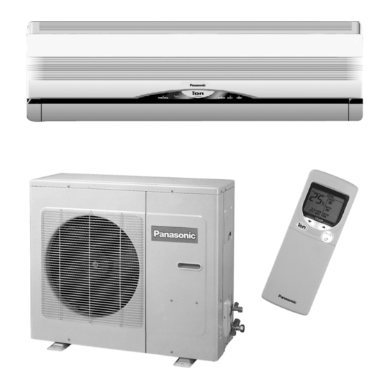
CS-W18CKE CU-W18CKE
CS-W24CKE CU-W24CKE
Page
2
3
6
10
12
13
14
15
15
16
20
22
27
© 2003 Matsushita Industrial Corp. Sdn. Bhd.
(11969-T). All rights reserved. Unauthorized copying
and distribution is a violation of law.
Order No. MAC0310029C2
Air Conditioner
Page
28
28
29
29
30
31
35
43
43
46
49
53
53
Advertisement
Table of Contents


Need help?
Do you have a question about the CS-W18CKE and is the answer not in the manual?
Questions and answers