Table of Contents
Advertisement
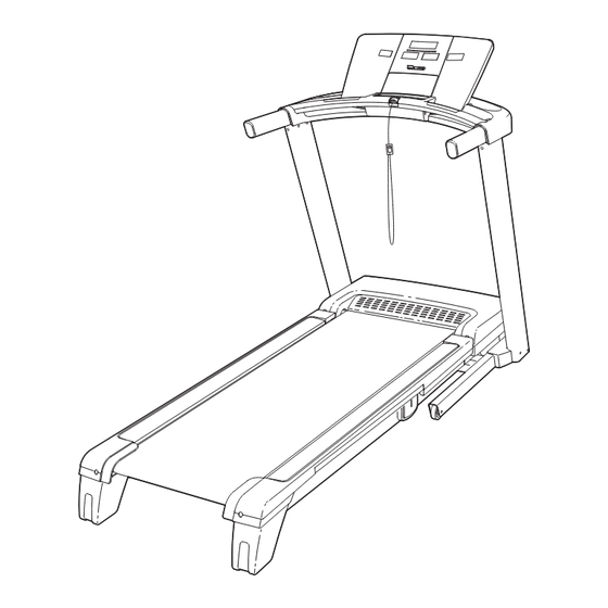
Model No. NETL14909.0
Serial No.
Write the serial number in the space
above for reference.
Serial Number
Decal
QUESTIONS?
If you have questions, or if there
are missing parts, please contact
us at the numbers or addresses
listed below:
Call: 08457 089 009
Outside UK: 0 (44) 113 3877133
Fax: 0 (44) 113 3877125
E-mail: csuk@iconeurope.com
Website: www.iconsupport.eu
Write:
ICON Health & Fitness, Ltd.
Unit 4
Revie Road Industrial Estate
Revie Road, Beeston
Leeds, LS11 8JG
UK
CAUTION
Read all precautions and instruc-
tions in this manual before using
this equipment. Save this manual
for future reference.
With Universal Dock for iPod
®
USER'S MANUAL
www.iconeurope.com
Advertisement
Table of Contents

Related Manuals for NordicTrack NETL14909.0


Summary of Contents for NordicTrack NETL14909.0
- Page 1 With Universal Dock for iPod ® Model No. NETL14909.0 USER'S MANUAL Serial No. Write the serial number in the space above for reference. Serial Number Decal QUESTIONS? If you have questions, or if there are missing parts, please contact us at the numbers or addresses...
-
Page 2: Table Of Contents
Apply the decal in the location shown. Note: The decals may not be shown at actual size. NordicTrack is a registered trademark of ICON IP, Inc. iPod is a trademark of Apple Computer, Inc., registered in the U.S. and other countries. -
Page 3: Important Precautions
IMPORTANT PRECAUTIONS WARNING: To reduce the risk of serious injury, read all important precautions and in- structions in this manual and all warnings on your treadmill before using your treadmill. ICON as- sumes no responsibility for personal injury or property damage sustained by or through the use of this product. - Page 4 19. Never leave the treadmill unattended while it 23. Inspect and properly tighten all parts of the is running. Always remove the key, unplug treadmill regularly. DANGER: the power cord, and switch the reset/off cir- cuit breaker to the off position when the Always unplug the power treadmill is not in use.
-
Page 5: Before You Begin
BEFORE YOU BEGIN Thank you for selecting the revolutionary NordicTrack ing this manual, please see the front cover of this man- ® T12si treadmill with Universal Dock for iPod . The ual. To help us assist you, note the product model ®... -
Page 6: Assembly
ASSEMBLY Assembly requires two persons. Set the treadmill in a cleared area and remove all packing materials. Do not dispose of the packing materials until assembly is completed. Note: The underside of the treadmill walking belt is coated with high-performance lubricant. During shipping, some lubricant may be transferred to the top of the walking belt or the shipping carton. -
Page 7: The Treadmill Onto Its Left Side. Partially Fold The
1. Make sure that the power cord is unplugged. Remove the 3/8" Nut (8), the 3/8" x 2" Bolt (4), and the shipping bracket (A) from the Base (83). Repeat this step on the other side of the treadmill. Discard the shipping brackets. The Bolts and Nuts will be used in steps 3 and 6. -
Page 8: Do Not Fully Fold The Frame Yet
4. Identify the Right Upright (78) and the Right Upright Spacer (79), which are marked with “Right” stickers. Insert the Upright Wire (38) through the Right Upright Spacer (79) as shown. Set the Right Upright Spacer on the Base (83). Be careful not to pinch the Upright Wire. - Page 9 7. Set the Left Upright Spacer (76) on the Base (83). Hold a Bolt Spacer (80) inside the lower end of the Left Upright (74). Insert a 3/8" x 4 1/2" Bolt (6) with a 3/8" Star Washer (9) into the Left Upright and the Bolt Spacer.
- Page 10 9. Set the handrail assembly on the Uprights (74, 78). Be careful not to pinch the wires. Handrail Assembly Attach the handrail assembly to the Uprights (74, 78) with six 5/16" x 1" Bolts (7) and six 5/16" Star Washers (10) as shown. See assembly steps 5 and 7.
- Page 11 11. Insert the wires from the console assembly into the handrail assembly. Attach the console assembly to the handrail as- Console sembly with four 1/4" x 3/4" Bolts (5). Be careful Assembly not to pinch the wires. Handrail Assembly Wires 12.
-
Page 12: How To Use The Chest Pulse Sensor
HOW TO USE THE CHEST PULSE SENSOR HOW TO PUT ON THE CHEST PULSE SENSOR • Store the chest pulse sensor in a warm, dry place. Do not store the chest pulse sensor in a plastic bag The chest pulse sensor consists of two components: or other container that may trap moisture. -
Page 13: Operation And Adjustment
OPERATION AND ADJUSTMENT THE PRE-LUBRICATED WALKING BELT Your treadmill features a walking belt coated with high-performance lubricant. IMPORTANT: Never apply sili- cone spray or other substances to the walking belt or the walking platform. Such substances will deterio- rate the walking belt and cause excessive wear. HOW TO PLUG IN THE POWER CORD This product must be earthed. - Page 14 CONSOLE DIAGRAM FEATURES OF THE CONSOLE goals. For example, lose unwanted pounds with the 8- week Weight Loss workout, or train for a long-distance The treadmill console offers an impressive array of run with the Marathon workout. iFit workouts automati- features designed to make your workouts more effec- cally control the treadmill while the voice of a personal tive and enjoyable.
-
Page 15: Manual Mode
HOW TO TURN ON THE POWER HOW TO USE THE MANUAL MODE IMPORTANT: If the treadmill has been exposed to 1. Insert the key into the console. cold temperatures, allow it to warm to room tem- perature before turning on the power. If you do not See HOW TO TURN ON THE POWER at the left. - Page 16 5. Monitor your progress with the displays. To reset the displays, press the Stop button, re- move the key, and then reinsert the key. The matrix—When you 6. Measure your heart rate if desired. select the manual mode, the matrix will display a Note: If you use the handgrip pulse sensor and 400 meter (1/4-mile) the chest pulse sensor at the same time, the...
- Page 17 HOW TO USE A PERFORMANCE WORKOUT ing segment indicates the speed setting for the cur- rent segment. At the end of each segment, a series 1. Insert the key into the console. of tones will sound and the next segment of the profile will begin to flash.
- Page 18 HOW TO USE A HEART RATE WORKOUT 5. Start the workout. CAUTION: Press the Start button or the Speed increase but- ton to start the workout. A moment after you press If you have heart prob- the button, the treadmill will automatically adjust to lems, or if you are over 60 years of age and the first speed and incline settings of the workout.
- Page 19 To stop the workout at any time, press the Stop the Set Weight increase and decrease buttons re- button. To restart the workout, press the Start but- peatedly to enter your weight. Press the Enter but- ton. The walking belt will begin to move at 1 mph; ton below the Set Weight buttons.
- Page 20 HOW TO USE THE CUSTOM WORKOUTS CENTER height of the flashing segment indicates the Current Segment 1. Insert the key into the console. speed setting for the cur- rent segment. At the end See HOW TO TURN ON THE POWER on page 15. of each segment, a se- ries of tones will sound 2.
-
Page 21: How To Use Ifit Card
HOW TO USE AN IFIT CARD 3. Start the workout. iFit cards are available separately. To purchase iFit Press the Start button or the Speed increase button cards, go to www.iFit.com or call the telephone num- to start the workout. A moment after you press the ber on the front cover of this manual. - Page 22 THE INFORMATION MODE An “M” for metric kilome- ters or an “E” for English The console features an information mode that keeps miles will appear in the track of the total number of hours that the treadmill has display. Press the Speed been used and the total distance that the walking belt increase button to change has moved.
- Page 23 HOW TO USE THE SOUND SYSTEM HOW TO ADJUST THE CUSHIONING SYSTEM Remove the key from the console and unplug the This product has been designed specifically to work power cord. The treadmill features a cushioning sys- with iPod and has been certified by the developer to meet Apple performance standards.
-
Page 24: How To Fold And Move The Treadmill
HOW TO FOLD AND MOVE THE TREADMILL HOW TO FOLD THE TREADMILL FOR STORAGE Before folding the treadmill, adjust the incline to the lowest position. If you do not do this, you may damage the treadmill when you fold it. Remove the key and unplug the power cord. -
Page 25: To Lower The Treadmill For Use
HOW TO LOWER THE TREADMILL FOR USE Frame 1. Hold the upper end of the treadmill with your right hand. Pull the latch knob to the left and hold it. It may be neces- sary to push the frame forward as you pull the knob to the left. -
Page 26: Troubleshooting
TROUBLESHOOTING Most treadmill problems can be solved by following the steps below. Find the symptom that applies, and follow the steps listed. If further assistance is needed, please see the front cover of this manual. PROBLEM: The power does not turn on SOLUTION: a. - Page 27 Remove the three #8 x 3/4" Screws (1) and care- fully pivot the Motor Hood (61) off. Locate the Reed Switch (71) and the Magnet (50) on the left side of the Pulley (51). Turn the Pulley until the Magnet is aligned with the Reed Switch. Make sure that the gap between the Magnet and 1/8 in.
- Page 28 PROBLEM: The walking belt is off-center or slips when walked on SOLUTION: a. If the walking belt is off-center, first remove the key and UNPLUG THE POWER CORD. If the walking belt has shifted to the left, use the hex key to turn the left idler roller bolt clockwise 1/2 of a turn;...
-
Page 29: Exercise Guidelines
EXERCISE GUIDELINES WARNING: Burning Fat—To burn fat effectively, you must exer- cise at a low intensity level for a sustained period of Before beginning this time. During the first few minutes of exercise, your or any exercise program, consult your physi- body uses carbohydrate calories for energy. -
Page 30: Part List
PART LIST—Model No. NETL14909.0 R0909A To locate the parts listed below, see the EXPLODED DRAWING near the end of this manual. Key No. Qty. Description Key No. Qty. Description #8 x 3/4" Screw Drive Roller/Pulley #8 x 1" Tek Screw 15 1/2"... - Page 31 Key No. Qty. Description Key No. Qty. Description Latch Cap #8 x 3/4" Ground Bolt Transformer Chest Pulse Receiver 5/32" Hex Key Receptacle Lift Motor Spacer Handrail Hood Screw Tray Right Handrail Trim Pulse Bar Ground Wire Frame/Roller Ground Wire Console Back Electronics Bracket –...
-
Page 32: Exploded Drawing
EXPLODED DRAWING A—Model No. NETL14909.0 R0909A... - Page 33 EXPLODED DRAWING B—Model No. NETL14909.0 R0909A...
- Page 34 EXPLODED DRAWING C—Model No. NETL14909.0 R0909A...
- Page 35 EXPLODED DRAWING D—Model No. NETL14909.0 R0909A...
-
Page 36: Ordering Replacement Parts
ORDERING REPLACEMENT PARTS To order replacement parts, please see the front cover of this manual. To help us assist you, be prepared to pro- vide the following information when contacting us: • the model number and serial number of the product (see the front cover of this manual) •...
Need help?
Do you have a question about the NETL14909.0 and is the answer not in the manual?
Questions and answers