KTM 690 SMC Owner's Manual
Hide thumbs
Also See for 690 SMC:
- Spare parts manual (59 pages) ,
- Owner's manual (196 pages) ,
- Owner's manual (186 pages)
Table of Contents
Advertisement
Quick Links
Advertisement
Table of Contents

Related Manuals for KTM 690 SMC


Summary of Contents for KTM 690 SMC
- Page 1 OWNER'S MANUAL 2009 690 SMC EU 690 SMC AUS/UK ART. NO. 3211365en...
- Page 3 DEAR KTM CUSTOMER Congratulations on your decision to buy a KTM motorcycle. You are now the owner of a state-of-the-art sports motorcycle that will give you DEAR KTM CUSTOMER enormous pleasure if you service and maintain it accordingly. We wish you great pleasure riding the vehicle! Enter the serial numbers of your vehicle below.
- Page 4 Reproduction, even in part, is permitted only with the express written permission of the copyright owner. ISO 9001(12 100 6061) According to the international quality management standard ISO 9001, KTM uses quality assurance processes that lead to the maximum possible quality of the products.
-
Page 5: Table Of Contents
CONTENTS Setting the clock .............. 27 CONTENTS MEANS OF REPRESENTATION ..........7 Combination instrument - display ODO ....... 28 IMPORTANT NOTES ............... 8 Combination instrument - setting/resetting TRIP 1....28 VIEW OF VEHICLE..............12 Combination instrument - setting/resetting TRIP 2....29 View of vehicle, front left side.......... - Page 6 Checking chain dirt ............73 Important maintenance work to be carried out by an Cleaning the chain............73 authorized KTM workshop. (as additional order)....53 Checking the chain tension ..........74 MAINTENANCE WORK ON CHASSIS AND ENGINE ....55 Adjusting the chain tension ..........75 Jacking up front of motorcycle ...........
- Page 7 CONTENTS Checking the tire condition..........103 Checking engine oil level..........136 Checking spoke tension........... 104 Changing the engine oil and filter, cleaning the oil screens ..............136 Checking tire air pressure ..........105 Draining the engine oil ..........137 Removing the seat ............106 Mounting the seat ............
- Page 8 CONTENTS AUXILIARY SUBSTANCES........... 176 STANDARDS..............178 INDEX ................179...
-
Page 9: Means Of Representation
All work marked with this symbol requires specialist knowledge and technical understanding. In the interest of your own safety, have these jobs done in an authorized KTM workshop! There, your motorcycle will be serviced optimally by specially trained experts using the specialist tools required. -
Page 10: Important Notes
Warranty The work prescribed in the service plan must only be carried out in an authorized KTM workshop and confirmed in the service record; oth- erwise all warranty claims will be disregarded. No warranty claim can be met for damage resulting from manipulation and/or other changes to the vehicle. - Page 11 Spare parts, accessories In the interests of your own safety, use only spare parts and accessories approved and/or recommended by KTM, and have these fitted in an authorized KTM workshop. KTM accepts no liability for other products and any resulting damage.
- Page 12 IMPORTANT NOTES Environment Offroad motorcycling is a wonderful sport and we naturally hope that you will be able to enjoy it to the fullest. However, it is a potential problem for the environment and can lead to conflicts with other persons. But if you use your motorcycle responsibly, you can ensure that such problems and conflicts do not have to occur.
- Page 13 IMPORTANT NOTES Grades of risks Danger Identifies a danger that will immediately and invariably lead to fatal or serious permanent injury if the appropriate measures are not taken. Warning Identifies a danger that is likely to lead to fatal or serious injury if the appropriate measures are not taken. Caution Identifies a danger that will possibly lead to light injury if the appropriate measures are not taken.
-
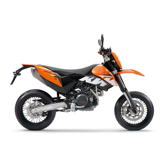
Page 14: View Of Vehicle
VIEW OF VEHICLE View of vehicle, front left side 600637-10... - Page 15 VIEW OF VEHICLE Hand brake lever Clutch lever Seat Filler cap Handrail Front brake caliper Shift lever Engine number Side stand Footrest Seat release strap...
-
Page 16: View Of Vehicle, Rear Right
VIEW OF VEHICLE View of vehicle, rear right 600638-10... - Page 17 VIEW OF VEHICLE Ignition/steering lock Light switch, flasher switch, horn button Rear mirror Combination instrument Emergency OFF switch, electric starter button Throttle grip Chassis number Brake caliper, rear Passenger footrest Shock absorber, rebound damping Foot brake pedal Level viewer, engine oil...
-
Page 18: Location Of Serial Numbers
LOCATION OF SERIAL NUMBERS Chassis number The chassis number is stamped on the steering head on the right. 100217-10 Type label Type label is located on the upper right frame tube below the seat. 100218-10... -
Page 19: Key Number
LOCATION OF SERIAL NUMBERS Key number The key number can be found on the KEYCODECARD. Info You need the key number to order a spare key. Keep the KEYCODECARD in a safe place. 100179-10 Engine number The engine number is stamped on the left side of the engine under the engine sprocket. -
Page 20: Fork Part Number
LOCATION OF SERIAL NUMBERS Fork part number The fork part number is stamped on the inner side of the fork stub. 600480-10 Shock absorber part number The shock absorber part number is on the right of the shock absorber. ... -
Page 21: Controls
CONTROLS Clutch lever The clutch lever is fitted on the left side of the handlebar. The clutch is hydraulically operated and self-adjusting. 700542-01 Hand brake lever The hand break lever is fitted on the right side of the handlebar. ... -
Page 22: Light Switch
CONTROLS Light switch The light switch is fitted on the left side of the handlebar. Possible states Low beam on – Light switch is turned downwards. In this position, the low beam and tail light are switched on. High beam on – Light switch is turned upwards. In this position, the high beam and the tail light are switched on. -
Page 23: Horn Button
CONTROLS Horn button The horn button is fitted on the left side of the handlebar. Possible states • Horn button in neutral position pressed – The horn is operated in this position. • Horn button 100224-10 Emergency OFF switch The emergency OFF switch is fitted on the left side of the handlebar. -
Page 24: Electric Starter Button
CONTROLS Electric starter button The electric starter button is fitted on the right side of the handlebar. Possible states • Electric starter button in basic position pressed – In this position, the electric starter is actuated. • Electric starter button 100226-10 Ignition/steering lock The ignition/steering lock... -
Page 25: Combination Instrument
CONTROLS Combination instrument The combination instrument is installed in front of the handlebar. The combination instrument is divided into 4 function areas. Function buttons Tachometer Indicator lights Display 700116-01 Combination instrument - function buttons 5.10 You can change the display mode with the MODE button ... -
Page 26: Combination Instrument - Tachometer
CONTROLS Combination instrument - tachometer 5.11 The tachometer shows the engine speed in revolutions per minute. The red marking shows the excess speed range of the engine. 100118-10 Combination instrument - indicator lamps 5.12 The indicator lamps offer additional information about the operating state of the motorcy- cle. -
Page 27: Combination Instrument - Display
CONTROLS FI warning lamp (MIL) lights up/flashes orange – The OBD has detected an emission- or safety-critical fault. Battery warning lamp lights up red – Voltage in vehicle system too low. Combination instrument - display 5.13 When you switch on the ignition, all display segments light up for a second as a function test. -
Page 28: Combination Instrument - Speedometer
CONTROLS Combination instrument - speedometer 5.14 The speed is shown in kilometers per hour km/h or in miles per hour mph. 700114-01 Setting kilometers or miles 5.15 Info If you change the unit, the value ODO is retained and converted accordingly. Making the setting according to the country. -
Page 29: Combination Instrument - Time
CONTROLS – Switch on the ignition by turning the ignition key to position ON – Press the MODE button repeatedly until the ODO mode is active. – Keep the MODE button pressed until the display mode changes from km/h to mph or from mph to km/h. -
Page 30: Combination Instrument - Display Odo
CONTROLS – Switch on the ignition by turning the ignition key to position ON – Press the MODE button repeatedly until the ODO mode is active. – Keep the MODE button and the SET button pressed simultaneously. The time display begins to flash. –... -
Page 31: Combination Instrument - Setting/Resetting Trip 2
CONTROLS – Switch on the ignition by turning the ignition key to position ON – Press the MODE button repeatedly until the TRIP 1 mode is active. – Keep the SET button pressed. The TRIP 1 display is set to 0.0. 700121-01 Combination instrument - setting/resetting TRIP 2 5.20... -
Page 32: Combination Instrument - Trip F Display
CONTROLS Combination instrument - TRIP F display 5.21 If the fuel level drops to the reserve mark, the display automatically changes to TRIP F and starts to count from 0.0, regardless of the previous display mode. Info Parallel to the TRIP F display, the fuel warning light switches on. 700123-01 Combination instrument - coolant temperature indicator 5.22... -
Page 33: Opening Filler Cap
CONTROLS Opening filler cap 5.23 – Lift the cover of the filler cap and insert the ignition key. – Turn the ignition key 90° counterclockwise and remove the filler cap. Info The filler cap has a tank air vent system. 100227-10 Closing filler cap 5.24... -
Page 34: Handrails
CONTROLS Handrails 5.25 The handrails are used for moving the motorcycle around. When you have a passenger, the passenger can hold on the handrails during the journey. 100229-10 Seat release 5.26 The seat can be released using strap 100230-10... -
Page 35: Passenger Footrests
CONTROLS Passenger footrests 5.27 The passenger footrests can be folded up and down. Possible states Passenger footrests folded up – For operation without a passenger. • Passenger footrests folded down – For operation with a passenger. • 600640-01 Shift lever 5.28 The shift lever is mounted on the left side of the engine. -
Page 36: Foot Brake Pedal
CONTROLS The gear positions can be seen in the photograph. The neutral or idle position is between the first and second gears. 600484-11 Foot brake pedal 5.29 The footbrake pedal is located in front of the right footrest. The footbrake pedal operates the rear brake. 600485-10... -
Page 37: Side Stand
CONTROLS Side stand 5.30 The side stand is coupled with the safety electric starter system - see the riding instruc- tions. Possible states Side stand folded out – The vehicle can be supported on the side stand. The safety •... -
Page 38: General Tips And Hints On Putting Into Operation
The front and rear wheels must be fitted with tires with similar tread patterns to prevent loss of control over the vehicle. Warning Danger of accidents Uncontrollable handling characteristics due to non-approved and/or non-recommended tires/wheels. – Only tires/wheels approved by KTM and with the corresponding speed index should be used. Warning Danger of accidents Reduced road grip with new tires. –... -
Page 39: Running In The Engine
When using your vehicle, remember that others may feel disturbed by excessive noise. – Make sure that the pre-delivery inspection work has been carried out by an authorized KTM workshop. You receive a delivery certificate and the service record at vehicle handover. -
Page 40: Loading The Vehicle
GENERAL TIPS AND HINTS ON PUTTING INTO OPERATION Loading the vehicle Warning Danger of accidents Unstable riding behavior. – Do not exceed the maximum permitted weight and axle loads. The overall weight consists of: motorcycle operational and with a full tank, driver and passenger with protective clothing and helmet, baggage. Warning Danger of accidents Unstable handling characteristics due to incorrect mounting of suitcase and/or tank rucksack. - Page 41 GENERAL TIPS AND HINTS ON PUTTING INTO OPERATION Warning Danger of accidents Unstable handling characteristics due to slipped baggage. – Check the way your baggage is fixed regularly. Warning Danger of burns A hot exhaust system can burn baggage. – Fasten your baggage in such a way that it cannot be burned or singed by the hot exhaust system. –...
-
Page 42: Riding Instructions
RIDING INSTRUCTIONS Checks before putting into operation Info Make sure that the motorcycle is in a perfect technical condition before use. In the interests of riding safety, make a habit of making a general check before you ride. – Check the engine oil level. ( p. -
Page 43: Starting
RIDING INSTRUCTIONS Starting Danger Danger of poisoning Exhaust gases are poisonous and can result in unconsciousness and/or death. – When running the engine, always make sure there is sufficient ventilation, and do not start or run the engine in a closed space without an effective exhaust extraction system. - Page 44 RIDING INSTRUCTIONS – Turn the emergency OFF switch to the position – Switch on the ignition by turning the ignition key to position ON After you switch on the ignition, you can hear the fuel pump working for about 2 seconds.
-
Page 45: Starting Up
RIDING INSTRUCTIONS Starting up – Pull the clutch lever, engage 1st gear, release the clutch lever slowly and simultaneously open the throttle carefully. Shifting, riding Warning Danger of accidents An abrupt load alterations can cause the vehicle to get out of control. –... - Page 46 RIDING INSTRUCTIONS Warning Danger of accidents Reduced road grip with cold tires. – On every journey, take the first miles carefully at moderate speed until the tires reach operating temperature and optimal road grip is ensured. Warning Danger of accidents Reduced road grip with new tires. –...
- Page 47 If you continue with the coolant temperature warning lamp alight, you may have engine failure. Info If you hear unusual noises while riding, stop immediately, switch off the engine and contact an authorized KTM workshop. – When conditions allow (incline, road situation, etc.), you can shift into a higher gear.
-
Page 48: Braking
Clean or dry dirty or wet brakes by riding and braking gently. Warning Danger of accidents Reduced braking caused by spongy pressure point of front or rear brake. – Have the brake system checked in an authorized KTM workshop, and do not ride any further. -
Page 49: Stopping, Parking
RIDING INSTRUCTIONS Warning Danger of accidents Brake system failure. – If the foot brake pedal is not released, the brake linings drag permanently. The rear brake can fail due to overheating. Take your foot off the foot brake pedal if you do not want to brake. Warning Danger of accidents Longer stopping distance due to higher overall weight. - Page 50 RIDING INSTRUCTIONS Warning Danger of burns Some vehicle components get very hot when the machine is driven. – Do not touch hot components such as exhaust system, radiator, engine, shock absorber and brakes. Allow these components to cool down before starting work on them. Note Danger of damage The parked vehicle can roll away or fall over.
-
Page 51: Refueling
RIDING INSTRUCTIONS – Lock the steering by turning the handlebar fully to the left, pressing down the ignition key to position and turning it to position To make the steering lock engage more easily, move the handlebar a little to the left and right. Remove the ignition key. Refueling Danger Fire hazard Fuel can easily catch fire. - Page 52 RIDING INSTRUCTIONS – Switch off engine. – Open the filler cap. ( p. 31) – Fill the fuel tank with fuel up to measurement Guideline Measurement of 20 mm (0.79 in) Total fuel tank 12 l (3.2 US gal) Super unleaded (ROZ 95 / RON 95 / capacity, approx.
-
Page 53: Service Schedule
SERVICE SCHEDULE Important maintenance work to be carried out by an authorized KTM workshop. K10N K50A K100A Engine • • • • • Change the engine oil and filter, clean the oil screens. p. 136) • • Check and adjust valve clearance. - Page 54 SERVICE SCHEDULE K10N K50A K100A Attachments Check the headlamp setting. ( p. 122) • • • • • Check the functioning of the electrical equipment. • • • • • Check screws and nuts for tightness. • • • • •...
-
Page 55: Important Maintenance Work To Be Carried Out By An Authorized Ktm Workshop. (As Additional Order)
K50A: every 5,000 km (3,107 mi) / after every race K100A: every 10,000 km (6,214 mi) J1A: annually J2A: every 2 years Important maintenance work to be carried out by an authorized KTM workshop. (as additional order) K100A Carry out a complete fork service. •... - Page 56 SERVICE SCHEDULE J2A: every 2 years...
-
Page 57: Maintenance Work On Chassis And Engine
MAINTENANCE WORK ON CHASSIS AND ENGINE Jacking up front of motorcycle Note Danger of damage The parked vehicle can roll away or fall over. – Always place the vehicle on a firm and even surface. – Jack up the rear of the motorcycle. ( p. -
Page 58: Jacking Up Rear Of Motorcycle
MAINTENANCE WORK ON CHASSIS AND ENGINE Jacking up rear of motorcycle Note Danger of damage The parked vehicle can roll away or fall over. – Always place the vehicle on a firm and even surface. – Insert the work stand adapter in the work stand and screw it into the link forks. Work stand adapter (61029055110) Work stand rear (61029055100) –... -
Page 59: Fork/Shock Absorber
MAINTENANCE WORK ON CHASSIS AND ENGINE Fork/shock absorber The fork and the shock absorber offer many options of adapting the chassis to your riding style and the payload. Info To help you adapt the vehicle, we have summarized our findings in Table . -
Page 60: Adjusting The Rebound Damping Of The Fork
MAINTENANCE WORK ON CHASSIS AND ENGINE – Turn back counterclockwise by the number of clicks corresponding to the fork type. Guideline Compression damping Comfort 20 clicks Standard 15 clicks Sport 10 clicks Full payload 10 clicks Info Turn clockwise to increase damping, turn counterclockwise to reduce suspension damping. -
Page 61: Compression Damping Of The Shock Absorber
MAINTENANCE WORK ON CHASSIS AND ENGINE – Turn back counterclockwise by the number of clicks corresponding to the fork type. Guideline Rebound damping Comfort 15 clicks Standard 10 clicks Sport 5 clicks Full payload 5 clicks Info Turn clockwise to increase damping; turn counterclockwise to reduce suspension damping. - Page 62 MAINTENANCE WORK ON CHASSIS AND ENGINE Info The low-speed setting can be seen during the slow to normal compression of the shock absorber. – Turn adjusting screw clockwise with a screwdriver as far as the last perceptible click. Info Do not loosen nut ...
-
Page 63: Adjusting The High-Speed Compression Damping Of The Shock Absorber
MAINTENANCE WORK ON CHASSIS AND ENGINE Adjusting the high-speed compression damping of the shock absorber 9.10 Danger Danger of accidents The shock absorber is under high pressure. – The shock absorber is filled with highly compressed nitrogen, so never dismantle the shock absorber or carry out any mainte- nance on it yourself. -
Page 64: Adjusting The Rebound Damping Of The Shock Absorber
MAINTENANCE WORK ON CHASSIS AND ENGINE – Turn adjusting screw clockwise as far as it will go using an open end wrench. Info Do not loosen nut – Turn back counterclockwise by the number of turns corresponding to the shock absorber type. -
Page 65: Measuring The Unloaded Rear Wheel Sag
MAINTENANCE WORK ON CHASSIS AND ENGINE – Turn adjusting screw clockwise to the last perceptible click. – Turn back counterclockwise by the number of clicks corresponding to the shock absorber type. Guideline Rebound damping Comfort 20 clicks Standard 15 clicks Sport 10 clicks 100247-10... -
Page 66: Checking The Static Sag Of The Shock Absorber
MAINTENANCE WORK ON CHASSIS AND ENGINE Checking the static sag of the shock absorber 9.13 – Measure distance of rear wheel unloaded. ( p. 63) – Ask someone to help you by holding the motorcycle upright. – Measure the distance between the rear axle and the fixed point again. 0 0 A –... -
Page 67: Checking The Riding Sag Of The Shock Absorber
MAINTENANCE WORK ON CHASSIS AND ENGINE Checking the riding sag of the shock absorber 9.14 – Measure distance of rear wheel unloaded. ( p. 63) – With another person holding the motorcycle, sit on the saddle with full protective cloth- ing in a normal sitting position (feet on footrests) and bounce up and down a few times until the rear suspension levels out. -
Page 68: Bleeding The Fork Legs
MAINTENANCE WORK ON CHASSIS AND ENGINE Info Before changing the spring preload, make a note of the present setting, e.g., by measuring the length of the spring. – Remove the shock absorber. – After removing the shock absorber, clean it thoroughly. –... -
Page 69: Cleaning The Dust Boots Of The Fork Legs
MAINTENANCE WORK ON CHASSIS AND ENGINE – Remove bleeder screws briefly. Any excess pressure escapes from the interior of the fork. – Mount and tighten bleeder screws. Info Carry out this action on both fork legs. 100248-10 Cleaning the dust boots of the fork legs 9.17 –... -
Page 70: Removing The Fork Protector
MAINTENANCE WORK ON CHASSIS AND ENGINE Warning Danger of accidents Reduced braking due to oil or grease on the brake discs. – Always keep the brake discs free of oil and grease, and clean them with brake cleaner when necessary. – Clean and oil the dust boots and inner fork tube of both fork legs. -
Page 71: Installing The Fork Protector
Danger of accidents Unsafe riding behavior due to incorrect steering head bearing play. – The steering head bearing play should be adjusted immediately in an authorized KTM workshop. Info If the bike is driven for a longer time with play in the steering head bearing, the bearing and the bearing seats in the frame can be damaged after time. -
Page 72: Adjusting Play Of Steering Head Bearing
MAINTENANCE WORK ON CHASSIS AND ENGINE – Move the handlebar to the straight-ahead position. Move the fork legs to and fro in the direction of travel. No play should be noticeable in the steering head bearing. » If there is noticeable play present: –... -
Page 73: Handlebar Position
MAINTENANCE WORK ON CHASSIS AND ENGINE – Fully tighten screw Guideline Screw, top triple clamp 17 Nm (12.5 lbf ft) – Mount and tighten screw Guideline Loctite 243™ Screw, steering stem 20 Nm ® (14.8 lbf ft) – Check play of steering head bearing. -
Page 74: Adjusting Handlebar Position
MAINTENANCE WORK ON CHASSIS AND ENGINE Adjusting handlebar position 9.23 – Remove the four screws . Remove the handlebar clamp. Remove the handlebar and 0 0 1 lay it to one side. 0 0 2 Info Protect the motorcycle and its attachments from damage by covering them. Do not bend the cables and lines. -
Page 75: Checking Chain Dirt
MAINTENANCE WORK ON CHASSIS AND ENGINE Checking chain dirt 9.24 – Check the chain for coarse dirt accumulation. » If the chain is very dirty: – Clean the chain. ( p. 73) Cleaning the chain 9.25 Warning Danger of accidents Oil or grease on the tires reduces their grip. –... -
Page 76: Checking The Chain Tension
MAINTENANCE WORK ON CHASSIS AND ENGINE – After drying, apply chain spray. Onroad chain spray ( p. 177) Checking the chain tension 9.26 Warning Danger of accidents Danger caused by incorrect chain tension. – If the chain tension is too high, the components of the secondary power train (chain, engine sprocket, rear sprocket, bearings in transmission and rear wheel) are under additional load. -
Page 77: Adjusting The Chain Tension
MAINTENANCE WORK ON CHASSIS AND ENGINE – Lean the motorcycle on the side stand. – Shift gear to neutral. – Push the chain upward at a distance from the chain sliding guard and determine the chain tension Info The upper chain section must be taut. - Page 78 MAINTENANCE WORK ON CHASSIS AND ENGINE – Check the chain tension. ( p. 74) – Loosen nut – Loosen nuts – Adjust the chain tension by turning adjusting screws on the left and right. Guideline Chain tension 5 mm (0.2 in) Turn the left and right adjusting screws so that the markings on the left and right...
-
Page 79: Checking Rear Sprocket / Engine Sprocket For Wear
The engine sprocket, rear sprocket and chain should always be replaced together. For safety reasons, the chain has no chain joint. Always have the chain replaced in an authorized KTM workshop, where the necessary chain rivet tool is available. 100132-10 –... -
Page 80: Checking Chain Wear
A new chain will wear faster on an old, worn rear sprocket or engine 1 2 3 16 17 18 sprocket. 400409-10 For safety reasons, the chain has no chain joint. Always have the chain changed in an authorized KTM workshop, where they have the necessary special tools. -
Page 81: Adjusting Chain Guide
Mount and tighten screws Guideline Remaining screws, chassis 10 Nm (7.4 lbf ft) 600635-10 Checking brake discs 9.31 Warning Danger of accidents Reduced braking due to worn brake discs. – Worn brake discs should be replaced immediately in an authorized KTM workshop. -
Page 82: Adjusting Basic Position Of Handbrake Lever
MAINTENANCE WORK ON CHASSIS AND ENGINE – Check the thickness of the front and rear brake discs in several places to ensure that it conforms to measurement Info Wear reduces the thickness of the brake disc in the area of the brake disc. -
Page 83: Checking The Front Brake Fluid Level
Danger of accidents Reduced braking due to old brake fluid. – Have the front and rear brake fluid replaced according to the service plan in an authorized KTM workshop. – Move the brake fluid reservoir mounted on the handlebar to a horizontal position. - Page 84 If brake fluid gets into your eyes, rinse thoroughly with water and contact a doctor immediately. Warning Danger of accidents Reduced braking due to old brake fluid. – Have the front and rear brake fluid replaced according to the service plan in an authorized KTM workshop. Warning Environmental hazard Problem materials cause environmental damage. –...
-
Page 85: Checking The Front Brake Linings
9.35 Warning Danger of accidents Reduced braking due to worn brake linings. – Worn brake linings should be replaced immediately in an authorized KTM workshop. Note Danger of accidents Reduced braking due to damaged brake discs. – If the brake linings are not changed in time, the steel brake lining carriers grind on the brake disc. The braking effect is greatly... -
Page 86: Changing The Front Brake Linings
Danger of accidents Reduced braking due to old brake fluid. – Have the front and rear brake fluid replaced according to the service plan in an authorized KTM workshop. Warning Danger of accidents Reduced braking due to oil or grease on the brake discs. - Page 87 Brake linings available from accessory suppliers are often not tested and approved for use on KTM vehicles. The construction and friction factor of the brake linings and therefore the brake power can differ considerably from the original KTM brake lin- ings.
-
Page 88: Removing Front Brake Linings
Removing front brake linings 9.37 Warning Danger of accidents Improper brake maintenance and repair. – Always have your brake system maintained and repaired in an authorized KTM workshop. – Press the spring hanger of the spring forwards and withdraw the bolt ... -
Page 89: Installing The Front Brake Linings
Brake linings available from accessory suppliers are often not tested and approved for use on KTM vehicles. The construction and friction factor of the brake linings and therefore the brake power can differ considerably from the original KTM brake lin- ings. - Page 90 MAINTENANCE WORK ON CHASSIS AND ENGINE – Position the brake calipers. Install the screws with the spacers 600621-10 – Insert brake linings . Position springs and install bolts Info The spring hanger of the springs must be positioned facing upwards.
-
Page 91: Checking Free Play Of Foot Brake Lever
MAINTENANCE WORK ON CHASSIS AND ENGINE Checking free play of foot brake lever 9.39 Warning Danger of accidents Brake system failure. – If there is no free travel on the foot brake pedal, pressure builds up on the rear brake in the brake system. The rear brake can fail due to overheating. -
Page 92: Checking Rear Brake Fluid Level
Danger of accidents Brake system failure. – If the brake fluid level falls below the MIN mark, this indicates a leakage in the brake system or worn-out brake linings. Have the brake system checked in an authorized KTM workshop, and do not ride any further. -
Page 93: Adding Rear Brake Fluid
MAINTENANCE WORK ON CHASSIS AND ENGINE Warning Danger of accidents Reduced braking due to old brake fluid. – Have the front and rear brake fluid replaced according to the service plan in an authorized KTM workshop. – Stand the vehicle upright. –... - Page 94 MAINTENANCE WORK ON CHASSIS AND ENGINE Warning Danger of accidents Reduced braking due to old brake fluid. – Have the front and rear brake fluid replaced according to the service plan in an authorized KTM workshop. Warning Environmental hazard Problem materials cause environmental damage. –...
-
Page 95: Checking The Rear Brake Linings
If there is wear or tearing: – Change the rear brake linings. p. 93) 100260-10 Changing the rear brake linings 9.44 Warning Danger of accidents Improper brake maintenance and repair. – Always have your brake system maintained and repaired in an authorized KTM workshop. - Page 96 Brake linings available from accessory suppliers are often not tested and approved for use on KTM vehicles. The construction and friction factor of the brake linings and therefore the brake power can differ considerably from the original KTM brake lin- ings.
- Page 97 MAINTENANCE WORK ON CHASSIS AND ENGINE – Stand the vehicle upright. – Remove the screw cap with the membrane – Press the brake caliper by hand on to the brake disc in order to press back the brake piston.
-
Page 98: Removing Front Wheel
MAINTENANCE WORK ON CHASSIS AND ENGINE – Insert the brake pads, insert the bolt and mount the split pin. – Operate the foot brake lever repeatedly until the brake linings lie on the brake disc and there is a tight spot. –... -
Page 99: Installing The Front Wheel
MAINTENANCE WORK ON CHASSIS AND ENGINE – Loosed screw and screw – Screw out screw about 6 turns, press your hand on the screw to push the wheel spin- dle out of the fork stub. Remove screw ... - Page 100 MAINTENANCE WORK ON CHASSIS AND ENGINE – Clean and grease the shaft seal rings and bearing surface of the distance bushings Long-life grease ( p. 177) – Insert the distance bushings. 600626-10 – Clean and grease the thread of the wheel spindle and screw ...
-
Page 101: Removing Rear Wheel
MAINTENANCE WORK ON CHASSIS AND ENGINE – Fully tighten screws Guideline Screw, front brake caliper M10x1.25 45 Nm Loctite ® 243™ (33.2 lbf ft) – Take the front from the work stand. ( p. 55) – Pull the front wheel brake and push down hard on the fork several times to align the fork legs. -
Page 102: Installing The Rear Wheel
MAINTENANCE WORK ON CHASSIS AND ENGINE – Push the rear wheel forwards as far as possible and take the chain off the rear sprocket. Warning Danger of accidents Reduced braking due to damaged brake discs. – Always lay the wheel down in such a way that the brake disc is not damaged. –... - Page 103 MAINTENANCE WORK ON CHASSIS AND ENGINE – Remove the bushing . Clean and grease the working surfaces of the bushing and shaft seal ring Long-life grease ( p. 177) – Clean and grease the thread of the wheel spindle and nut ...
-
Page 104: Checking The Rear Hub Rubber Dampers
MAINTENANCE WORK ON CHASSIS AND ENGINE Checking the rear hub rubber dampers 9.49 Info The engine power is transmitted from the rear sprocket to the rear wheel via 6 rubber dampers. They eventually wear out during operation. If the rubber dampers are not changed in time, the rear sprocket carrier and the rear hub will be damaged. –... -
Page 105: Checking The Tire Condition
The front and rear wheels must be fitted with tires with similar tread patterns to prevent loss of control over the vehicle. Warning Danger of accidents Uncontrollable handling characteristics due to non-approved and/or non-recommended tires/wheels. – Only tires/wheels approved by KTM and with the corresponding speed index should be used. Warning Danger of accidents Reduced road grip with new tires. –... -
Page 106: Checking Spoke Tension
If a tire is more than 5 years old: – Change the tires. Checking spoke tension 9.51 Warning Danger of accidents Unstable riding behavior due to loose spokes. – If you ride with loose spokes, the spokes can break. Have the spoke tension corrected in an authorized KTM workshop. -
Page 107: Checking Tire Air Pressure
MAINTENANCE WORK ON CHASSIS AND ENGINE Info A loose spoke can cause wheel imbalance, which leads to more loose spokes in a short time. If the spokes are too tight, they can break due to local overload. Check the spoke tension regularly, especially on a new motorcycle. –... -
Page 108: Removing The Seat
MAINTENANCE WORK ON CHASSIS AND ENGINE – Remove dust cap. – Check tire air pressure when tires are cold. Tire air pressure, Solo Front 2.0 bar (29 psi) Rear 2.0 bar (29 psi) Tire air pressure with passenger / fully loaded Front 2.0 bar (29 psi) Rear... -
Page 109: Mounting The Seat
MAINTENANCE WORK ON CHASSIS AND ENGINE Mounting the seat 9.54 – Hook slot of the seat onto screw , press the rear downward and at the same time push it forward. – Push locking pin into lock housing and push the back of the seat down until the ... -
Page 110: Installing The Battery
MAINTENANCE WORK ON CHASSIS AND ENGINE – Disconnect the negative (minus) cable of the battery. – Pull off the plug connector upwards. – Remove screws – Pull the retaining bracket of the battery forward and remove it. –... -
Page 111: Recharging The Battery
MAINTENANCE WORK ON CHASSIS AND ENGINE – Set the clock. ( p. 27) Recharging the battery 9.57 Warning Risk of injury Battery acid and battery gases cause serious chemical burns. – Keep batteries out of the reach of children. – Wear suitable protective clothing and goggles. –... - Page 112 MAINTENANCE WORK ON CHASSIS AND ENGINE Info Even if there is no load on the battery, it loses power every day. The charge state and the type of charge are very important for the service life of the battery. Fast recharging with a high charge current shortens the battery's service life. If the charge current, the charge voltage and the charge time are exceeded, electrolyte escapes through the breathing holes.
-
Page 113: Changing The Main Fuse
MAINTENANCE WORK ON CHASSIS AND ENGINE – Connect the battery charger to the battery. Switch on the battery charger. Battery charger (58429074000) You can also use the battery charger to test rest potential and start potential of the bat- tery, and to test the generator. With this device, you cannot overcharge the battery. Info Never remove lid ... - Page 114 – Insert the new main fuse. Fuse (58011109130) ( p. 164) Info If the new fuse burns out, contact an authorized KTM workshop. A reserve fuse is located in the starter relay. – Check that the electrical equipment is functioning properly.
-
Page 115: Changing The Fuses Of Power Consumers
MAINTENANCE WORK ON CHASSIS AND ENGINE Changing the fuses of power consumers 9.59 Info The fuse box containing the fuses of the individual power consumers is located under the seat. – Switch off all power consumers and switch off the engine. –... - Page 116 MAINTENANCE WORK ON CHASSIS AND ENGINE – Remove the defective fuse. Guideline Fuse 1 - 10A - ignition, combination instrument, alarm system (optional) Fuse 2 - 10A - clock, ignition (EFI control unit) Fuse 3 - 10A - throttle valve control unit Fuse 4 - 10A - fuel pump Fuse 5 - 10A - radiator fan Fuse 6 - 10A - horn, brake light, flasher light, alarm system (optional)
-
Page 117: Adjusting The Engine Characteristic
164) Fuse (75011088015) ( p. 164) Info If the new fuse burns out, contact an authorized KTM workshop. Put a new spare fuse in the fuse box for future use if needed. – Checking the function of power consumers. - Page 118 MAINTENANCE WORK ON CHASSIS AND ENGINE – Pull the Map‑Select switch and holder upward off of the retaining bracket. – Pull the Map‑Select switch out of the holder. 600641-10 – Turn the adjusting wheel until the desired digit is next to marking ...
-
Page 119: Removing The Headlight Mask With The Headlight
MAINTENANCE WORK ON CHASSIS AND ENGINE Removing the headlight mask with the headlight 9.61 – Switch off all power consumers and switch off the engine. – Cover the fender with a cloth to protect it from damage. – Remove the screws on the left and right. -
Page 120: Installing The Headlight Mask With The Headlight
MAINTENANCE WORK ON CHASSIS AND ENGINE Installing the headlight mask with the headlight 9.62 – Connect the connectors of headlight and flasher lights – Check lighting function. 100294-11 – Remove the cloth from the fender, attach the headlight mask to points on the fender ... -
Page 121: Changing The Headlight Bulb
MAINTENANCE WORK ON CHASSIS AND ENGINE – Position groove on counterpiece 700543-01 – Position brake-hose guide . Mount and tighten screws Guideline Remaining screws, chassis 10 Nm (7.4 lbf ft) 100296-10 Changing the headlight bulb 9.63 Note Damage to reflector Keep the glass of the bulb free of grease. -
Page 122: Changing The Parking Light Bulb
MAINTENANCE WORK ON CHASSIS AND ENGINE – Pull off connector – Take off rubber cap of the headlight bulb. 600610-10 – Detach spring bar – Remove headlight bulb – Insert a new headlight bulb into the headlight housing. Headlight (H4/P43t) ( p. -
Page 123: Changing The Flasher Bulb
MAINTENANCE WORK ON CHASSIS AND ENGINE – Remove rubber cap 600610-12 – Pull bulb socket out of the reflector. – Pull parking light bulb out of the bulb socket. – Insert a new parking light bulb in the bulb socket. Parking light (W2.1x9.5d) ( p. -
Page 124: Checking Headlamp Setting
MAINTENANCE WORK ON CHASSIS AND ENGINE – Remove the screw from the rear of the flasher housing. – Tilt headlamp diffuser forward carefully and take it off. – Press the flasher bulb carefully into the socket, turn it counterclockwise by about 30°, and take it out of the socket. -
Page 125: Adjusting The Headlight Range
MAINTENANCE WORK ON CHASSIS AND ENGINE – Check the headlamp setting. The boundary between light and dark must be exactly on the lower mark for a motor- cycle with driver. » If the boundary between light and dark does not meet specifications: –... - Page 126 MAINTENANCE WORK ON CHASSIS AND ENGINE – Remove screws . Remove filter box top 100285-10 Note Engine failure Unfiltered intake air has a negative effect on the service life of the engine. – Never ride the vehicle without an air filter since dust and dirt can get into the engine and result in increased wear.
-
Page 127: Installing The Air Filter
MAINTENANCE WORK ON CHASSIS AND ENGINE Installing the air filter 9.69 – Clean the air filter box. – Mount air filter Info The air filter must lie flush against the air filter box along the entire sealing sur- face ... -
Page 128: Cooling System
MAINTENANCE WORK ON CHASSIS AND ENGINE Cooling system 9.70 The water pump in the engine forces the coolant to flow. The pressure resulting from the warming of the cooling system is regulated by a valve in the radiator cap . - Page 129 MAINTENANCE WORK ON CHASSIS AND ENGINE Warning Danger of poisoning Coolants are poisonous and a health hazard. – Avoid contact between coolants and skin, eyes and clothing. If fuel gets into your eyes, rinse immediately with water and con- tact a doctor. Wash affected skin areas immediately with soap and water. If coolant is swallowed, contact a doctor immediately. Change clothes that have come into contact with coolants.
-
Page 130: Checking The Coolant Level
MAINTENANCE WORK ON CHASSIS AND ENGINE – Screw off the radiator cap – Check antifreeze of coolant. −25… −45 °C (−13… −49 °F) » If the antifreeze of the cooling liquid does not meet specifications: – Correct antifreeze of coolant. –... - Page 131 MAINTENANCE WORK ON CHASSIS AND ENGINE Warning Danger of poisoning Coolants are poisonous and a health hazard. – Avoid contact between coolants and skin, eyes and clothing. If fuel gets into your eyes, rinse immediately with water and con- tact a doctor. Wash affected skin areas immediately with soap and water. If coolant is swallowed, contact a doctor immediately. Change clothes that have come into contact with coolants.
-
Page 132: Draining The Coolant
MAINTENANCE WORK ON CHASSIS AND ENGINE – Screw off the radiator cap and check the coolant level in the radiator. The radiator must be completely full. » If the level of the cooling liquid does not meet specifications: – Correct the coolant level and find out the cause of the loss. -
Page 133: Filling The Cooling System
MAINTENANCE WORK ON CHASSIS AND ENGINE – Stand the motorcycle upright. – Place a suitable container under the engine. – Remove screw . Remove the radiator cap. – Completely drain the coolant. – Mount screw with a new seal ring and tighten it. ... - Page 134 MAINTENANCE WORK ON CHASSIS AND ENGINE – Refill the coolant. Alternative 1 Coolant ( p. 172) Alternative 2 Coolant (mixed ready to use) ( p. 172) – Fill the radiator completely with coolant. Mount radiator cap 600619-10 – Remove the cap from compensating tank and add coolant to the level shown in the ...
-
Page 135: Adjusting Basic Position Of Clutch Lever
MAINTENANCE WORK ON CHASSIS AND ENGINE Adjusting basic position of clutch lever 9.75 Info Turn the adjusting screw clockwise to increase the distance between the clutch lever and the handlebar. Turn the adjusting screw counterclockwise to decrease the distance between the clutch lever and the handlebar. The range of adjustment is limited. -
Page 136: Checking Play In Gas Bowden Cable
MAINTENANCE WORK ON CHASSIS AND ENGINE – Remove screws – Remove cover with membrane – Check the fluid level. Fluid level under top level of container 4 mm (0.16 in) » If the level of the coolant does not meet specifications: –... -
Page 137: Adjusting The Play In The Gas Bowden Cable
Adjusting the play in the gas Bowden cable 9.78 – Move the handlebar to the straight-ahead position. – Use the KTM diagnostics tool to set the throttle stepper motor to the neutral position. – Loosen counter nut – Set the play in the gas Bowden cable by turning the adjusting screw ... -
Page 138: Checking Engine Oil Level
MAINTENANCE WORK ON CHASSIS AND ENGINE Checking engine oil level 9.79 Info The engine oil level must be checked when the engine is at operating temperature. – Stand the motorcycle upright on a horizontal surface. Condition The engine is at operating temperature. –... -
Page 139: Draining The Engine Oil
MAINTENANCE WORK ON CHASSIS AND ENGINE Draining the engine oil 9.81 Warning Danger of scalding Engine oil and gear oil get very hot when the motocycle is driven. – Wear suitable protective clothing and gloves. If you scald yourself, hold the affected area under cold water immediately. Warning Environmental hazard Problem materials cause environmental damage. -
Page 140: Removing The Oil Filter
MAINTENANCE WORK ON CHASSIS AND ENGINE – Thoroughly clean the oil drain plug with a magnet. – Mount the oil drain plug with the magnet and seal ring and tighten it. Guideline Oil drain plug with magnet M12x1.5 20 Nm (14.8 lbf ft) 100201-01 Removing the oil filter... - Page 141 MAINTENANCE WORK ON CHASSIS AND ENGINE – Remove screws . Remove the oil filter cover with the O-ring. – Pull oil filter out of the oil filter housing. Circlip pliers reverse (51012011000) 100202-10 – Remove screws . Remove oil filter with the O-ring.
-
Page 142: Installing The Oil Filter
MAINTENANCE WORK ON CHASSIS AND ENGINE Installing the oil filter 9.83 – Insert oil filters – Oil the O-rings of the oil filter cover. Mount oil filter covers – Mount and tighten the screws. Guideline Screw, oil filter cover 6 Nm (4.4 lbf ft) 100204-10 Cleaning the oil screens... - Page 143 MAINTENANCE WORK ON CHASSIS AND ENGINE – Remove plug with oil screen and the O-rings. 100205-10 – Remove plug with oil screen and the O-rings. – Completely drain the remaining engine oil. – Thoroughly clean the parts and sealing area. 100206-10 –...
-
Page 144: Filling Up With Engine Oil
MAINTENANCE WORK ON CHASSIS AND ENGINE – Position oil screen with the O-rings. – Mount and tighten plug with the O-ring. Guideline Plug, oil screen M20x1.5 15 Nm (11.1 lbf ft) 100208-10 Filling up with engine oil 9.85 Info Too little engine oil or poor-quality engine oil results in premature wear to the engine. -
Page 145: Adding Engine Oil
MAINTENANCE WORK ON CHASSIS AND ENGINE Danger Danger of poisoning Exhaust gases are poisonous and can result in unconsciousness and/or death. – When running the engine, always make sure there is sufficient ventilation, and do not start or run the engine in a closed space without an effective exhaust extraction system. - Page 146 MAINTENANCE WORK ON CHASSIS AND ENGINE Danger Danger of poisoning Exhaust gases are poisonous and can result in unconsciousness and/or death. – When running the engine, always make sure there is sufficient ventilation, and do not start or run the engine in a closed space without an effective exhaust extraction system.
-
Page 147: Troubleshooting
Reconnect coupling of fuel hose connection. connected – Socket connector of cable harness oxi- Clean socket connector and treat it with contact dized spray. – Defect in fuel injection system Read the error memory with the KTM diagnostics tool and correct the fault. - Page 148 – Fuel filter very dirty Have the fuel filter changed. – Defect in fuel injection system Read the error memory with the KTM diagnostics tool and correct the fault. – Engine overheats. Too little coolant in cooling system Check the cooling system for leakage.
- Page 149 TROUBLESHOOTING Faults Possible cause Action – Headlight and parking light not func- Fuse 7 blown Change the fuses of power consumers. tioning p. 113) – Flasher light, brake light and horn not Fuse 6 blown Change the fuses of power consumers. functioning p.
-
Page 150: Flashing Code
FLASHING CODE Flashing code FI of warning lamp 02 FI warning lamp (MIL) flashes briefly 2x (MIL) Possible cause Malfunction in ignition pulse generator circuit Flashing code FI of warning lamp 06 FI warning lamp (MIL) flashes briefly 6x (MIL) Possible cause Input signal of throttle valve sensor circuit A too low Input signal of throttle valve sensor circuit A too high... - Page 151 FLASHING CODE Flashing code FI of warning lamp 13 FI warning lamp (MIL) flashes 1x long, 3x short (MIL) Possible cause Input signal from intake air temperature sensor too low Input signal from intake air temperature sensor too high Flashing code FI of warning lamp 14 FI warning lamp (MIL) flashes 1x long, 4x short (MIL) Possible cause...
- Page 152 FLASHING CODE Flashing code FI of warning lamp 26 FI warning lamp (MIL) flashes 2x long, 6x short (MIL) Possible cause Malfunction in circuit of Hall sensor throttle valve control Flashing code FI of warning lamp 27 FI warning lamp (MIL) flashes 2x long, 7x short (MIL) Possible cause Malfunction in the EPT control unit power supply circuit...
- Page 153 FLASHING CODE Flashing code FI of warning lamp 54 FI warning lamp (MIL) flashes 5x long, 4x short (MIL) Possible cause Interruption/short-circuit to ground in secondary air valve circuit Flashing code FI of warning lamp 58 FI warning lamp (MIL) flashes 5x long, 8x short (MIL) Possible cause Malfunction of release of throttle stepper motor in EPT mode...
- Page 154 FLASHING CODE Flashing code FI of warning lamp 92 FI warning lamp (MIL) flashes 9x long, 2x short (MIL) Possible cause Malfunction in voltage supply circuit of EPT control unit (internal)
-
Page 155: Cleaning
CLEANING Cleaning motorcycle 12.1 Note Material damage Damage and destruction of components by high-pressure cleaning equipment. – Never clean the vehicle with high-pressure cleaning equipment or a strong water-jet. The excessive pressure can penetrate electrical components, plug connectors, Bowden cables and bearings, etc., and can damage or destroy these parts. Warning Environmental hazard Problem materials cause environmental damage. - Page 156 CLEANING Warning Danger of accidents Reduced braking due to wet or dirty brakes. – Clean or dry dirty or wet brakes by riding and braking gently. – After cleaning, ride the vehicle a short distance until the engine warms up, and then apply the brakes. Info The heat produced causes water at inaccessible positions in the engine and the brakes to evaporate.
-
Page 157: Conservation For Winter Operation
CONSERVATION FOR WINTER OPERATION Conservation for winter operation 13.1 Info If you use the motorcycle in winter, you must expect salt on the roads. You should therefore take precautions against aggressive road salt. If you have ridden the vehicle on salted roads, clean it with cold water. Warm water would reinforce the effect of the salt. –... -
Page 158: Storage
Storage temperature of battery without direct sunshine. 0… 35 °C (32… 95 °F) – The storage place should be dry and not subject to large temperature differences. Info KTM recommends jacking up the motorcycle. – Jack up the rear of the motorcycle. ( p. 56) –... -
Page 159: Putting Into Operation After Storage
STORAGE – Cover the motorcycle with a porous sheet or blanket. Info Do not use non-porous materials since they prevent humidity from escaping, thus causing corrosion. Avoid running the engine for a short time only. Since the engine cannot warm up properly, the water vapor produced during combustion condenses and causes valves and exhaust system to rust. -
Page 160: Technical Data - Engine
TECHNICAL DATA - ENGINE Design 1-cylinder 4-stroke engine, water-cooled Displacement 654 cm³ (39.91 cu in) Stroke 80 mm (3.15 in) Bore 102 mm (4.02 in) Compression ratio 11.8:1 Control OHC, 4 valves controlled via rocker arm, chain drive Valve diameter, intake 40 mm (1.57 in) Valve diameter, exhaust 34 mm (1.34 in) -
Page 161: Capacity- Engine Oil
TECHNICAL DATA - ENGINE Mixture preparation Electronic fuel injection Ignition Contactless controlled fully electronic ignition with digital ignition adjustment Generator 12 V, 224 W Spark plug NGK LKAR 8AI - 9 Spark plug electrode gap 0.9 mm (0.035 in) Cooling Water cooling, permanent circulation of coolant by water pump Starting aid Electric starter, automatic decompressor... -
Page 162: Technical Data - Engine Tightening Torques
TECHNICAL DATA - ENGINE TIGHTENING TORQUES ® Oil hole plug self-tapping 9 Nm (6.6 lbf ft) Loctite 243™ ® Screw, membrane fixation 2.5 Nm (1.84 lbf ft) Loctite 243™ – Hose clamp, intake flange 1.5 Nm (1.11 lbf ft) ® Oil jet, conrod lubrication 2 Nm (1.5 lbf ft) Loctite... - Page 163 TECHNICAL DATA - ENGINE TIGHTENING TORQUES ® Screw, locking lever 10 Nm (7.4 lbf ft) Loctite 243™ – Screw, rocker arm shaft 12 Nm (8.9 lbf ft) ® Screw, shift drum locating 10 Nm (7.4 lbf ft) Loctite 243™ ® Screw, shift lever 10 Nm (7.4 lbf ft) Loctite...
- Page 164 TECHNICAL DATA - ENGINE TIGHTENING TORQUES ® Oil hole plug M10x1 15 Nm (11.1 lbf ft) Loctite 243™ – Plug, drain hole of water pump M10x1 15 Nm (11.1 lbf ft) – Plug, oil bore for oil radiator M10x1 15 Nm (11.1 lbf ft) –...
-
Page 165: Technical Data - Chassis
TECHNICAL DATA - CHASSIS Frame Lattice frame made of chrome molybdenum steel tubing, powder- coated Fork WP Suspension Up Side Down 4860 ROMA Shock absorber WP Suspension 4618 with Pro‑Lever deflector Suspension travel Front 275 mm (10.83 in) Rear 265 mm (10.43 in) Brake system Front Disc brake with radially screwed four-piston brake caliper, floating... -
Page 166: Lighting Equipment
TECHNICAL DATA - CHASSIS Steering head angle 63° Wheelbase 1,480±15 mm (58.27±0.59 in) Seat height unloaded 910 mm (35.83 in) Ground clearance unloaded 290 mm (11.42 in) Weight without fuel approx. 139.5 kg (307.5 lb.) Maximum permissible front axle load 150 kg (331 lb.) Maximum permissible rear axle load 200 kg (441 lb.) -
Page 167: Capacity - Fuel
120/70 ZR 17 M/C 58W TL 160/60 ZR 17 M/C 69W TL Pirelli Dragon Supercorsa Pro Pirelli Dragon Supercorsa Pro Additional information is available in the Service section under: http://www.ktm.com Capacity - fuel 17.2 Total fuel tank capacity, approx. 12 l (3.2 US gal) Super unleaded (ROZ 95 / RON 95 / PON 91) ( p. -
Page 168: Technical Data - Fork
TECHNICAL DATA - FORK Fork part number 14.18.7E.12 Fork WP Suspension Up Side Down 4860 ROMA Compression damping Comfort 20 clicks Standard 15 clicks Sport 10 clicks Full payload 10 clicks Rebound damping Comfort 15 clicks Standard 10 clicks Sport 5 clicks Full payload 5 clicks... -
Page 169: Technical Data - Shock Absorber
TECHNICAL DATA - SHOCK ABSORBER Shock absorber part number 15.18.7E.12 Shock absorber WP Suspension 4618 with Pro‑Lever deflector Compression damping, high-speed Comfort 1.5 turns Standard 1 turn Sport 0.5 turn Full payload 0.5 turn Compression damping, low-speed Comfort 20 clicks Standard 15 clicks Sport... - Page 170 TECHNICAL DATA - SHOCK ABSORBER Riding sag 70… 80 mm (2.76… 3.15 in) Fitted length 400 mm (15.75 in) Shock absorber fluid Shock absorber oil (SAE 2.5) (50180342S1) ( p. 174)
-
Page 171: Technical Data - Chassis Tightening Torques
TECHNICAL DATA - CHASSIS TIGHTENING TORQUES – Spoke nipple, front wheel M4.5 4 Nm (3 lbf ft) – Remaining screws, chassis 4 Nm (3 lbf ft) – Screw, electrical holder 3 Nm (2.2 lbf ft) – Screw, exhaust heat shield 8 Nm (5.9 lbf ft) ®... - Page 172 TECHNICAL DATA - CHASSIS TIGHTENING TORQUES ® Screw, rear brake disc 14 Nm (10.3 lbf ft) Loctite 243™ – Screw, SLS valve 4 Nm (3 lbf ft) – Screw, voltage regulator/rectifier 8 Nm (5.9 lbf ft) Nut, manifold on cylinder head 25 Nm (18.4 lbf ft) Copper paste ®...
- Page 173 TECHNICAL DATA - CHASSIS TIGHTENING TORQUES ® Engine carrying screw 45 Nm (33.2 lbf ft) Loctite 243™ – Remaining nuts, chassis 50 Nm (36.9 lbf ft) – Remaining screws, chassis 45 Nm (33.2 lbf ft) ® Screw, bottom shock absorber 45 Nm (33.2 lbf ft) Loctite 243™...
-
Page 174: Substances
– Guideline – Use only brake fluid that complies with the specified standards (see specifications on the container) and that possesses the corre- ® sponding properties. KTM recommends Castrol and Motorex products. Supplier Castrol – RESPONSE BRAKE FLUID SUPER DOT 4 ®... - Page 175 178) (SAE 10W/60) – KTM LC4 2007+ Guideline – Use only engine oils that comply with the specified standards (see specifications on the container) and that possess the corresponding ® properties. KTM recommends Motorex products. Synthetic engine oil Supplier ® Motorex –...
- Page 176 – ISO VG (15) Guideline – Use only hydraulic fluid that complies with the specified standards (see specifications on the container) and that possesses the corre- ® sponding properties. KTM recommends Motorex products. Supplier ® Motorex – Hydraulic Fluid 75 Shock absorber oil (SAE 2.5) (50180342S1)
- Page 177 SUBSTANCES Super unleaded (ROZ 95 / RON 95 / PON 91) According to – DIN EN 228 (ROZ 95 / RON 95 / PON 91)
-
Page 178: Auxiliary Substances
AUXILIARY SUBSTANCES Chain cleaner Specification – ® KTM recommends Motorex products. Supplier ® Motorex – Chain Clean 611 Cleaning and polishing materials for metal, rubber and plastic Specification – ® KTM recommends Motorex products. Supplier ® Motorex – Protect & Shine 645... - Page 179 AUXILIARY SUBSTANCES Long-life grease Specification – ® KTM recommends Motorex products. Supplier ® Motorex – Fett 2000 Motorcycle cleaner Specification – ® KTM recommends Motorex products. Supplier ® Motorex – Moto Clean 900 Onroad chain spray Specification – ® KTM recommends Motorex products.
-
Page 180: Standards
STANDARDS JASO T903 MA Different technical development directions required a new specification for 4-stroke motorcycles – the JASO T903 MA Standard. Ear- lier, engine oils from the automobile industry were used for 4-stroke motorcycles because there was no separate motorcycle specification. Whereas long service intervals are demanded for automobile engines, high performance at high engine speeds are in the foreground for motorcycle engines. -
Page 181: Index
INDEX Removing front brake linings ..... 86 INDEX Brakes ........46 Accessories . - Page 182 INDEX setting clock ....... . 27 Engine oil setting kilometers or miles ..... . . 26 adding .
- Page 183 INDEX Front wheel installing ........97 Light switch .
- Page 184 INDEX Parking ........47 Seat Parking light bulb mounting...
- Page 185 INDEX Steering lock ........22 Stopping ........47 Warranty .
- Page 186 *3211365en* 3211365en 11/2008 Photo: Mitterbauer KTM-Sportmotorcycle AG 5230 Mattighofen/Austria http://www.ktm.com...
Need help?
Do you have a question about the 690 SMC and is the answer not in the manual?
Questions and answers