Table of Contents
Advertisement
Quest 215 Dual
Quest Dry
Installation, Operation and Maintenance Instructions
Installation, Operation and Maintenance Instructions
– Read and Save These Instructions –
This manual is provided to acquaint you with the dehumidi-
fier so that installation, operation and maintenance can
proceed successfully. Ultimate satisfaction depends on the
quality of installation and a thorough understanding of this
equipment. The dehumidifier is built around tested engi-
neering principles and has passed a thorough inspection for
quality of workmanship and function.
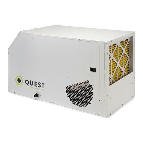
The Quest 215 Dual is the largest capacity of the group. This
unit removes up to 215 pints of water per day using only 6.9
amps/230V. Ideally suited for commercial gardens and green
houses.
Features:
•
Industry-leading efficiency, most efficient on the market
today
•
Patented, optimized air-to-air heat exchanger
•
High-efficiency, long-life impeller fan
•
Quiet operation
•
Superior air filtration (MERV-11 standard)
•
Auto-restart after power outages
•
Environmentally friendly R410A refrigerant
•
Low voltage control
Specifications subject to change without notice.
Water Removal Rates (Pints/Day)
215 pints
80˚F, 60% (AHAM)
4201 Lien Rd
Madison, WI 53704
www.QuestHydro.com
1
PATENTS:
D570,988
8,069,681
9,052,132
(215 Dual)
Toll-Free 1-877-420-1330
info@QuestHydro.com
TS-929
12/15
Advertisement
Table of Contents

Related Manuals for Quest Engineering 215 Dual


Summary of Contents for Quest Engineering 215 Dual
- Page 1 The Quest 215 Dual is the largest capacity of the group. This unit removes up to 215 pints of water per day using only 6.9 amps/230V. Ideally suited for commercial gardens and green houses.
-
Page 2: Table Of Contents
Quest 215 Dual Installation, Operation and Maintenance Instructions Table of Contents Safety Precautions ..............3 1. Intended Application .............4 2. Registrations ................4 3. Specifications ...............4 4. Installation ................ 5 4.1 Location ................ 5 4.2 Electrical Requirements ..........5 4.3 Condensate Removal ........... 6 4.4 Install Diagram .............. -
Page 3: Safety Precautions
Safety Precautions Read the installation, operation and maintenance instructions carefully before installing and operating this device. Proper adherence to these instructions is essential to obtain maximum benefit from your Quest 215 Dual indoor air quality system. READ AND SAVE THESE INSTRUCTIONS •... -
Page 4: Intended Application
In order to efficiently control humidity levels, the area in which the dehumidifier is to be operated must be free of water intrusion or excessive fresh (outside) air infiltration. Before installing the Quest 215 Dual, water intrusion and air infiltration problems should be addressed or noted in calculations. -
Page 5: Installation
Installation, Operation and Maintenance Instructions 4. Installation 4.1 Location The Quest 215 Dual can be installed in a variety of locations to meet the owner’s needs as listed below. In all cases keep the following cautions in mind: • It is designed to be installed INDOORS IN A SPACE THAT IS PROTECTED FROM RAIN AND FLOODING. -
Page 6: Condensate Removal
Installation, Operation and Maintenance Instructions The remote controls of the Quest 215 Dual are powered by a low voltage circuit (24 VAC) and must NEVER contact or be connected to a high voltage circuit. The control wires leaving the Quest 215 Dual and the remote control panels are numbered and color-coded to prevent confusion. -
Page 7: Ducting
Fan only on : Connect yellow and green (or brown) wires. The Quest 215 Dual can be equipped with various accessories to enhance its operation. A remote control must be used Accessory power : 24volt AC power supply available for HVAC accessories between yellow and with the Quest 215 Dual. - Page 8 WARNING: Allowing yellow wire to contact red or white wire Quest 215 Dual Installation, Operation and Maintenance Instructions will destroy the transformer. Dehumidifier on : Connect yellow and blue wires. Fan only on : Connect yellow and green (or brown) wires.
-
Page 9: Optional Dehumidifier & Ventilation System Controller
6. Optional Dehumidifier & Ventilation System Controller Control Part No. 4027370 When used with Quest 215 Dual Whole Structure Ventilating Dehumidifiers, the DEH 3000/3000R allows end- users the ability to monitor and control relative humidity levels in their structure. Major Operations... -
Page 10: Maintenance
To access the air filter, remove the filter access panel from the end of the Quest 215 Dual. The filter should be readily visible and can be removed by pulling them straight out of the Quest 215 Dual. -
Page 11: Technical Description
Installation, Operation and Maintenance Instructions 8.2 Technical Description The Quest 215 Dual uses a refrigeration system similar to an air conditioner's to remove heat and moisture from incoming air, and add heat to the air that is discharged (See Figure 15). - Page 12 Quest 215 Dual Installation, Operation and Maintenance Instructions Compressor cycles on and off. Dehumidification is being called for. No fan call. 1. Low ambient temperature and/or humidity causing unit to cycle through defrost mode. 2. Defective compressor overload (Sec. 7.6A).
-
Page 13: Refrigerant Charging
Quest 215 Dual Installation, Operation and Maintenance Instructions Unit Test to determine problem: 1. Detach field control wiring connections from main unit. 2. Connect the yellow and green pigtails from the main unit together; only the impeller fan should run. Disconnect the wires. -
Page 14: B Replacing Burned Out Compressor
Quest 215 Dual Installation, Operation and Maintenance Instructions 4. Compressor terminals C and S: No continuity indicates an open start winding. The compressor must be replaced. Normal start winding resistance is 3 to 7 ohms. 5. Compressor terminals C and R: No continuity indicates an open run winding. The compressor must be replaced. Normal run winding resistance is .5 to 2 ohms. -
Page 15: C Replacing Compressor-Nonburn Out
The humidity control is an adjustable switch that closes when the relative humidity of the air in which it is located rises to the dial set point. It opens when the RH drops 4 to 6% below the set point. If the Quest 215 Dual does not run, try turning the humidity control clockwise until it reaches the stop and the knob pointer points at “Max Dry”... -
Page 16: Electric Ventilation Damper
The pump also contains a safety float switch. The white leads from this switch extend from beneath the pump cover. This switch should be installed in series with the field wire that connects the blue (#5) lead from the Quest 215 Dual to the blue (#5) lead on the control panel. -
Page 17: Electrical Schematic
Quest 215 Dual Installation, Operation and Maintenance Instructions Electric Schematics of the Quest 215 Dual COMPRESSOR OPTIONAL DAMPER BLK-20 RELAY GRN-2 BLOWER GRN-17 YEL-6 SWITCH 13 14 BLOWER N.O. MAKE SURE WIRE IS RED-5 RELAY CAPPED IF DAMPER IS NOT USED... -
Page 18: Service Parts List
4031086-05 1 E-Coat Evaporator Coil 4035235-02 1 (215 Dual) Capacitor, 4029510 Filter/Drier Fan, 5 MFD, 370V, Dry 4032229 (215 Dual) Thermostat, Defrost Control 4020924 Relay, SPDT, 24V, 15A 4036493 (215 Dual) Compressor 4022484 Relay, SPST, 24V, 30A 4036516 (215 Dual) Compressor Overload... -
Page 19: Optional Parts List
Quest 215 Dual Installation, Operation and Maintenance Instructions Optional Parts List PART NO. QTY. DESCRIPTION 4020175 Controller, Humidity 4028614 Pump Kit (110-120V) 4028607 Supply Duct Kit 4028610 Return Duct Kit 4027370 DEH 3000 Control 4028531 DEH 3000R Control, Remote 4036668... -
Page 20: Warranty
(but all warranty periods will be extended by the period of time, if any, that the Quest 215 Dual Dehumidifier is out of service while awaiting covered warranty service).
Need help?
Do you have a question about the 215 Dual and is the answer not in the manual?
Questions and answers