
Subscribe to Our Youtube Channel
Related Manuals for BCM ED440BX


Summary of Contents for BCM ED440BX
- Page 1 Advanced Advanced Socket 370 Socket 370 Motherboard Motherboard ED440BX ED440BX User’s Manual...
-
Page 2: Declaration
Declaration Rights: No part of this manual, including but not limited to the products and software described in it, may be reproduced, transmitted, transcribes, stored in a retrieval system, or translated in any form or by any means without the expressed written permission of the manufacture. -
Page 3: Compliance & Certificate
Compliance & Certificate Compliance & Certificate & & & & ISO 9002 Certificate: ISO 9002 Certificate: This device was produced in our plant with advanced quality system certified by DNV QA Ltd. in according to ISO 9002. This Certificate is valid for: DESIGN &... -
Page 4: Easy Installation
Easy Installation Easy Installation Easy Installation Steps Easy Installation Steps The following “Easy Installation” steps are for users accustomed to the assembly of a computer system. For those individuals requiring more specific information, please refer to the more detailed descriptions located within the latter chapters of this manual. -
Page 5: Table Of Contents
2. Features 2. Features Declaration ......................2 Compliance & Certificate ................... 3 Easy Installation....................4 Introduction......................8 1.1 How To Use This Manual ................8 1.2 Check Your Device Items................8 2. Features ......................9 2.1 Features Of The Motherboard ..............9 3. - Page 6 2. Features 2. Features 4.3.6 Halt on ....................34 4.3.7 Memory....................35 4.4 Advanced BIOS Features Menu ..............35 4.4.1 Virus Warning ..................35 4.4.2 Processor Number Feature ..............36 4.4.3 ATA 100 chipset...................36 4.4.4 First Boot Device..................36 4.4.5 Second Boot Device................36 4.4.6 Third Boot Device.................36 4.4.7 Security Option ..................36 4.4.8 OS Select for DRAM >...
- Page 7 2. Features 2. Features 4.7.14 Time(Min.) Alarm................42 4.7.15 Wake Up On LAN................42 4.7.16 IRQ[3-7,8-15],NMI ................42 4.7.17 Primary IDE 0..................42 4.7.18 Primary IDE 1..................42 4.7.19 Secondary IDE 0 ................42 4.7.20 Secondary IDE 1 ................42 4.7.21 Floppy Disk ..................42 4.7.22 Serial Port ..................42 4.8 PnP/PCI Configurations Menu..............43 4.8.1 PNP OS Installed .................43 4.8.2 Reset Configuration Data ..............43...
-
Page 8: Introduction
The standard package should contain the following items. If you find any of these items be missing or damaged, please contact your retailer. Ø 1 ED440BX motherboard Ø 1 CD with drivers for ED440BX motherboard Ø 1 Quick-Start guide CHECK ITEMS... -
Page 9: Features
2. Features 2. Features 2.1 Features Of The Motherboard 2.1 Features Of The Motherboard This product is based on the “ ATX” form factor. It features the advanced Multimedia function and provides support for business PC maker. This motherboard incorporates Intel 82440BX AGP/PCI/ISA chipset and Promise Raid IDE Bus Controller. - Page 10 2. Features 2. Features Ø System Memory: 4 DIMM sockets support up to 1GB using 16/64/128/256Mb technology Supports up to 4 double-sided DIMMs at 100 MHz (133 optional) memory bus Un-buffered, NON-ECC / ECC DIMM support Ø On Board PCI IDE: 2 X PCI Bus Master IDE Ports (Up to 4 IDE Devices) Support PIO Mode 0, 1, 2, 3 Supports Enhanced IDE PIO mode 3 and 4, 17MB/sec.
-
Page 11: Installation
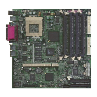
Installation 3.1 Motherboard Layout & Main Parts... -
Page 12: Connectors List
Installation Connectors List Front Panel Connectors Reset Refer to Sec. 3.6.6 LAN LED Refer to Sec. 3.6.6 HDD LED Refer to Sec. 3.6.6 Power Switch Refer to Sec. 3.6.6 Power LED Refer to Sec. 3.6.6 Speaker Refer to Sec. 3.6.6 Back Panel Connectors PS/2-style keyboard and mouse connectors Refer to Sec. -
Page 13: Precaution Before Start
Installation Precaution Before Start Static Electricity Damage: Static electricity can easily damage your motherboard. Observing a few basic precautions can help safeguard against damage that could result in expensive repairs. Follow the simple measures below to protect your equipment from static electricity damage. -
Page 14: Slots And Connectors
Installation 3.2 Slots And Connectors This motherboard requires jumper setting for some features. The following graphic shows you how to set a proper jumper setting. PIN 1 PIN 1 Note: In the following pages, the triangle s mark stands for pin 1 of connectors. 3.3 CPU (Central Processing Unit) This motherboard supports a PGA 370 Intel Celeron/Coppermine PGA family processor. -
Page 15: Install Cpu
Installation 3.3.1 Install CPU Please follow the below steps to install your CPU, and configure the types and speed in accordingly to the Processor Jumper Setting List. Step 1: Pull the handling bar of the socket upward to the other end to loosen the socket’s openings. -
Page 16: System Memory (Dram)
Installation 3.4 System Memory (DRAM) 3.4.1 DIMM (Dual Inline Memory Module) The motherboard features four 168-pin DIMM sockets, share memory module. If you have only one DIMM RAM, note that you must insert it into DIMM 1. You can configure the system memory size from 8MB to 512MB in a variety of ways by using different combinations of the two 168-pin DIMM. -
Page 17: Dimm Module Combinations
Installation If the pin 1 of the DIMM module does not line up with pin 1 of the socket, the DIMM module will not be inserted correctly into the socket. Be careful not to misfit the DIMM Module into DIMM sockets in wrong direction. This module can be inserted into the socket only one way. -
Page 18: Expansion Slot
Installation 3.5 Expansion Slot This motherboard contains 1 PCI / ATX Riser slot (Up to support 1 Full-length and 1 Low Profile 32 bit PCI BUS mastering cards). -
Page 19: Connectors
Installation 3.6 Connectors This motherboard contains IDE, floppy, power input, front panel and additional connectors. S e c o n d a r y I D E S e c o n d a r y I D E P r i m a r y I D E P r i m a r y I D E 3.6.1 Primary IDE Connector (J20, 39-pin block, Black) This connector supports two primary channel IDE devices via a ribbon cable. -
Page 20: Floppy Drive Connector (J26, 33-Pin Block)
Installation 3.6.3 Floppy Drive Connector (J26, 33-pin block) The FDC sub-system can control three types of floppy drives (1.2, 1.44 and 2.88MB) or compatible tape drives. The connection to the floppy drive is via a header (J26). The floppy disk interface includes 48mA drivers and inputs on the drive interface. -
Page 21: Power Input Connector (J24, 20-Pin Block)
Installation 3.6.4 Power Input Connector (J24, 20-pin block) This connector supports one standard ATX power supply. When connecting, make sure the lock key matches the hook attached on a power supply cable. The power cord should be unplugged when you connect it. -
Page 22: Front Panel Connectors (J15, 20-Pin)
Installation 3.6.5 Front Panel connectors (J 3.6.5 Front Panel connectors (J15 15, 20 , 20- - pin) pin) Power Switch, Power LED, Reset, Sleep and HDD LED. SPEAKER LAN 2 LAN 1 GRN/YEL PWR System HDD A HDD B Fault RESET Reset Switch Connector (2-pin) This connector supports the front panel case-mounted reset button. -
Page 23: Back Panel Connectors
Installation This connector supports the ATX case-mounted Power Switch, which in turn supports System Suspend function. When the BIOS sets the Power Button function to “Suspend”, the system can be set to the suspended mode once you push the power switch for no longer then 4 seconds. If the power switch is pushed down for over 4 seconds the system will be totally Power Off. - Page 24 Installation Mouse USB2 Printer Port Keyboard USB1 COM1 LAN 2 LAN 1 PS/2 Keyboard and Mouse Ports The motherboard offers 1 PS/2 Keyboard and 1 PS/2 Mouse port. Mouse Keyboard...
- Page 25 Installation Universal Serial Bus (USB) Ports The motherboard has two USB connectors. USB devices provide a more convenient operating environment and improve data transferring capacity. True Plug & Play. This new bus technology will support over 127 different peripherals through a Hub. USB1 USB2 Parallel Port (Printer) The motherboard includes a parallel port (EPP/ECP compatible).
- Page 26 Installation Serial Port (COM1, J5/ VGA, J1) The motherboard has two serial ports (one on rare panel, one on board). The electrical characteristics are compliant with the EIA-232-D Serial Communications Specifications. The serial ports may be remapped over other installable serial ports or disabled through the BIOS.
-
Page 27: Additional Connectors
Installation 3.6.7 Additional Connectors WOR (Wake On Ring) (J17, 2-pin) This header is used for remote wakeup of the computer through a modem. Ring-In requires an add-in modem card with remote wakeup capabilities. The remote wakeup header on the add-in modem card must be connected to the onboard Ring- In header. -
Page 28: Ready To Turn On Power
Installation Ready To Turn On Power Check Again Is the CPU installed exactly and firmly into the socket (Sec. 3.3)? Are all the DRAM modules installed properly (Sec. 3.4)? Did you insert the expansion card (VGA, Sound… etc.) already (Sec. 3.5)? Are you sure that all the connectors (described in Sec 3.6) have been connected to their variable devices (Sec. - Page 29 Installation If the power-on-self-test goes well, hold down <Del> button on the keyboard to enter BIOS Setup. Next, follow the instructions in the next chapter, BIOS SETUP.
-
Page 30: Bios Setup
BIOS SETUP The motherboard uses AWARD BIOS, stored in a flash EEPROM. All of the configuration information will be stored in the CMOS. 4.1 BIOS Setup The AWARD BIOS is immediately activated when you first turn on the computer. The BIOS reads system configuration information in CMOS RAM and begins the process of checking the system and configuring it through the Power-On-Self-Test (POST). -
Page 31: Main Setup Menu
BIOS SETUP 4.2 Main Setup Menu When you enter the Award BIOS CMOS Setup Utility, a Main Menu appears on the screen. The Main Menu allows you to select from several Setup functions and two exit choices. Use the arrow keys to select among the items and press <ENTER> key to enter the sub-menu. -
Page 32: Standard Cmos Features Menu
BIOS SETUP Set Supervisor Password Change, set, or disable a supervisor password. The supervisor password allows complete access. Set User Password Change, set, or disable an user password. The user password generally allows only power-on access. Save & Exit Setup Save settings in nonvolatile CMOS RAM and exit Setup. -
Page 33: Hard Disks
BIOS SETUP 4.3.3 Hard Disks The BIOS supports up to four IDE drives. This section does not show information about other IDE devices, such as a CD-ROM drive, or about other hard drive types, such as SCSI drives. NOTE: We recommend that you select type AUTO for all drives. The BIOS can automatically detect the specifications and optimal operating mode of almost all IDE hard drives. -
Page 34: Drive A/B And Floppy 3 Mode Support
BIOS SETUP 4.3.4 Drive A/B and Floppy 3 Mode Support Select the correct specifications for the diskette drive(s) installed in the computer. Floppy Mode 3 Support is for LS-120 disk drives if used. None No diskette drive installed. 360K, 5.25 in 5-1/4 inch AT-type standard drive;... -
Page 35: Memory
BIOS SETUP 4.3.7 Memory RAM is the computer's working memory, where the computer stores programs and data currently being used, so they are accessible to the CPU. Modern personal computers may contain up to 64 MB, 128 MB, or more. Base Memory Typically 640 KB. -
Page 36: Processor Number Feature
BIOS SETUP should then run an anti-virus program. Keep in mind that this feature protects only the boot sector, not the entire hard drive. NOTE: Many disk diagnostic programs that access the boot sector table can trigger the virus-warning message. If you plan to run such a program, we recommend that you first disable the virus warning. -
Page 37: Advanced Chipset Features Menu
BIOS SETUP 4.5 Advanced Chipset Features Menu 4.5.1 DRAM Data Integrity Mode Non-ECC or ECC. Set Non-ECC for non-ECC memory modules, otherwise set at ECC. 4.5.2 Memory Hole At 15-16M In order to improve performance, certain space in memory is reserved for ISA cards. -
Page 38: Integrated Peripherals
BIOS SETUP 4.6 Integrated Peripherals 4.6.1 On-Chip Primary PCI IDE The chipset contains a PCI IDE interface with support for two IDE channels. Select Enabled to activate the primary IDE interface. Select Disabled to deactivate this interface. The choices are: Enabled, and Disabled. 4.6.2 On-Chip Secondary PCI IDE The chipset contains a PCI IDE interface with support for two IDE channels. -
Page 39: Onboard Serial Port 1
BIOS SETUP 4.6.6 Onboard Serial Port 1 This item allows you to determine access onboard serial port 1 controller with which I/O address. The choices are: 3F8/IRQ4, 2E8/IRQ3, 3E8/IRQ4, 2F8/IRQ3, Disabled, and Auto. 4.6.7 Onboard Serial Port 2 This item allows you to determine access onboard serial port 2 controller with which I/O address. -
Page 40: Power Management Setup Menu
BIOS SETUP 4.7 Power Management Setup Menu The Power Management Setup allows you to configure your system to most effectively save energy while operating in a manner consistent with your own style of computer use. 4.7.1 ACPI function ACPI (Advanced Configuration and Power Interface) evolves the existing motherboard configuration interfaces to support these advanced architectures in a more robust, and potentially more efficient manner. -
Page 41: Pm Timers
BIOS SETUP 4.7.2.1 PM Timers This category allows you to select the type (or degree) of power saving and is directly related to the following modes: HDD Power Down – When enabled and after the set time of system inactivity, the hard disk drive will be powered down while all other devices remain active. -
Page 42: Poweron By Ring
BIOS SETUP 4.7.10 PowerOn by Ring Enables or disables Power On by Ring. 4.7.11 Resume by Alarm Enables or disables alarm function to POWER ON the system. 4.7.12 Date(of Month) Alarm Select one: Everyday, 1 to 31. 4.7.13 Time (Hour) Alarm Set hh with 0-23. -
Page 43: Pnp/Pci Configurations Menu
BIOS SETUP 4.8 PnP/PCI Configurations Menu 4.8.1 PNP OS Installed Select Yes if you are using a Plug and Play capable operating system, otherwise select No if you need the BIOS to configure non-boot devices. 4.8.2 Reset Configuration Data Select Enabled to reset Extended System Configuration Date (ESCD) when you exit Setup if you have installed a new add-on and the system reconfiguration has caused such a serious conflict that the operating system cannot boot. -
Page 44: Pc Health Status
BIOS SETUP 4.9 PC Health Status 4.9.1 Case Open Warning To warn for the case being opened without authorization, enable require a chassis with case open sensor. Otherwise, by disabling will leave no warning when a case is opened. 4.9.2 CPU Warning Temperature Shows the warning message to inform you the CPU temperature reaches the value you set if enabled. -
Page 45: In0(V)
BIOS SETUP 4.9.7 IN0(V) Displays voltage value. 4.9.8 IN1(V) Displays voltage value. 4.9.9 IN2(V) Displays voltage value. 4.9.10 +5V Displays voltage value. 4.9.11 +12V Displays voltage value. 4.9.12 –12V Displays voltage value. 4.9.13 –5V Displays voltage value. 4.9.14 VBAT(V) Displays voltage value. 4.9.15 Warning_Beep Enable or Disable CPU or system fan fail warning, beep from system buzzer. -
Page 46: Change Supervisor Password
BIOS SETUP 4.12 Change Supervisor Password The BIOS setup will not be accessible unless you enter the correct password. Select “Set Supervisor Password” and press <ENTER> key, the screen will display the symbol “*” instead of characters entered. After the new password is entered, retype the new password as prompted and press <ENTER>... -
Page 47: Troubleshooting
Troubleshooting Troubleshooting 5.1 General Troubleshooting Tips Is your system properly assembled and configured? Make sure the BIOS setup is set to default/optimal settings. Pressing <F2> or <DEL> key to enter the setup, select Default or Optimal settings, then save and exit the setup. For Windows 2000 that require ACPI support, make sure the ACPI option on your BIOS is enable (Some EOL boards will not support it at all). - Page 48 Check your reseller for the warranty and exchange policies. Please note that BCM DO NOT BACK reseller’s warranty if it EXCEEDS BCM’s current warranty policy which is one year from the date of manufacture and the board is PAST BCM’s warranty...
Need help?
Do you have a question about the ED440BX and is the answer not in the manual?
Questions and answers