
Subscribe to Our Youtube Channel
Related Manuals for MCZ MUSA 2.0


Summary of Contents for MCZ MUSA 2.0
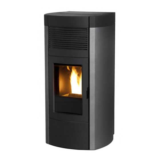
- Page 1 INSTALLATION GUIDE PELLET STOVE MUSA 2.0 Comfort Air 14 Instructions in English...
-
Page 2: Table Of Contents
TABLE OF CONTENTS TABLE OF CONTENTS ....................II INTRODUCTION ......................1 1-WARNINGS AND WARRANTY CONDITIONS ..............2 2-INSTALLATION ......................8 3-DRAWINGS AND TECHNICAL FEATURES ..............17 4-UNPACKING ......................19 5-MUSA STOVE ASSEMBLY ..................22 6-REMOVING THE BACK FOR MAINTENANCE ...............28 7-CONNECTIONS TO ADDITIONAL DEVICES ..............29 8-ELECTRICAL CONNECTION..................31 9-LOADING THE PELLETS ...................32 10-FIRST START-UP ....................33 11-REMOTE CONTROL MAX ..................35... -
Page 3: Introduction
REVISIONS TO THE PUBLICATION The content of this manual is strictly technical and the property of MCZ Group Spa. No part of this manual may be translated into other languages, adapted or reproduced, even in part, in other mechanical or electronic forms, photocopies, recordings or other, without the prior written authorisation from MCZ Group Spa. -
Page 4: 1-Warnings And Warranty Conditions
1-WARNINGS AND WARRANTY CONDITIONS SAFETY PRECAUTIONS • Installation, electrical connection, function test and maintenance must only be carried out by authorised and qualified personnel. • Install the product in accordance with all local and national legislation and regulations in force in the region or state. •... - Page 5 1-WARNINGS AND WARRANTY CONDITIONS • Do not put linen on the product to dry. Any drying racks or similar objects must be kept at a safe distance from the product. Fire hazard. • All liability for improper use of the product is entirely borne by the user and relieves the Manufacturer from any civil and criminal liability.
- Page 6 1-WARNINGS AND WARRANTY CONDITIONS • The product and the cladding must be stored in a dry place and must not be exposed to weathering. • It is recommended not to remove the feet that support the product in order to guarantee adequate insulation, especially if the flooring is made of flammable materials.
- Page 7 1-WARNINGS AND WARRANTY CONDITIONS INFORMATION: Please contact the retailer or qualified personnel authorised by the company to resolve a problem. • You must only use the fuel specified by the manufacturer. • When the product is switched on for the first time it is normal for it to emit smoke due to the paint heating for the first time. Therefore make sure the room in which it is installed is well ventilated.
- Page 8 1-WARNINGS AND WARRANTY CONDITIONS EXCLUSIONS The guarantee does not cover malfunctions and/or damage to the appliance that arise due to the following causes: • Damage caused during transportation or relocation • all parts that develop faults due to negligence or improper use, incorrect maintenance, installation that does not comply with the manufacturer’s instructions (always refer to the installation and use manual provided with the appliance) •...
- Page 9 1-WARNINGS AND WARRANTY CONDITIONS SPARE PARTS In the event of a malfunction, consult the retailer who will forward the call to the Technical Assistance Service. Use only original spare parts. The retailer or service centre can provide all necessary information regarding spare parts. We do not recommend waiting for the parts to be worn before having them replaced.
-
Page 10: 2-Installation
2-INSTALLATION The instructions in this chapter refer explicitly to the Italian installation regulation UNI 10683. In any case, always observe the domestic regulations in force. PELLETS Wood pellets are manufactured by hot-extruding compressed sawdust which is produced during the working of natural dried wood. The compactness of the material is guaranteed by the lignin contained in the wood itself and allows pellets to be produced without glue or binders. - Page 11 If particularly delicate objects are present, such as furniture, curtains or sofas, increase the stove clearance accordingly. If the floor is made of wood, it is recommended to fit a floor protection sheet in compliance with the Standards in force in the country of installation. MUSA 2.0 Non-flammable walls Flammable walls...
- Page 12 2-INSTALLATION FOREWORD This chapter on the Smoke Flue has been produced in reference to the prescriptions of European regulations (EN13384 - EN1443 - EN1856 - EN1457). The chapter provides indications for installing an efficient and correct smoke flue but is under no circumstances to substitute the regulations in force, which the qualified technician must be in possession of.
- Page 13 2-INSTALLATION TECHNICAL CHARACTERISTICS Have the efficiency of the flue checked by an authorised technician. The flue must be sealed against flue gasses, in a vertical direction without narrowing, be made with materials impermeable to smoke, condensation, thermally insulated and suitable to resist normal mechanical stress over time (we recommend fireplaces made of A/316 or refractory material with insulated round section double chamber).
- Page 14 2-INSTALLATION ROOF AT 60° ROOF AT 45° 45° 60° A = MIN. 2.60 metres A = MIN. 2.00 metres FIGURE 5 FIGURE 6 B = DISTANCE > 1.20 metres B = DISTANCE > 1.30 metres C = DISTANCE < 1.20 metres C = DISTANCE <...
- Page 15 2-INSTALLATION MAINTENANCE The flue must be kept clean, since the deposit of soot or unburned oils reduces the cross-section reducing the draft and thus compromising the efficient functioning of the heater and, if large build-ups accumulate, can catch fire. The flue and chimneypot must be cleaned and checked by a qualified chimney sweep at least once a year.
- Page 16 2-INSTALLATION EXTERNAL AIR INLET It is mandatory to provide an adequate external air intake that supplies the combustion air required for the product to work properly. The flow of air between the outside and the installation room may be direct, through an inlet in an external wall of the room; or indirect, via air intake from adjoining rooms and connecting permanently with the installation room (see Figure 9 b).
- Page 17 2-INSTALLATION DISTANCE (metres) The air inlet must be at a distance of: 1.5 m UNDER Windows, doors, smoke outlets, cavities, ..1.5 m HORIZONTALLY Windows, doors, smoke outlets, cavities, ..0.3 m ABOVE Windows, doors, smoke outlets, cavities, ..1.5 m AWAY from smoke outlet CONNECTION TO FLUE...
- Page 18 2-INSTALLATION EXAMPLES OF CORRECT INSTALLATION 1. Installation of Ø150mm flue with hole for the passage of the tube increased by: minimum 100 mm around the tube if next to non flammable parts such as cement, brick, etc.; or minimum 300 mm around the tube (or as prescribed by data tags) if next to flammable parts such as wood etc.
-
Page 19: 3-Drawings And Technical Features
3-DRAWINGS AND TECHNICAL FEATURES DRAWINGS AND CHARACTERISTICS DIMENSIONS OF MUSA 2.0 COMFORT AIR 14 Ø50 Ø60 Ø60 Ø80 Ø80 Ø50 Technical Dept. - All rights reserved - Reproduction is prohibited... - Page 20 3-DRAWINGS AND TECHNICAL FEATURES TECHNICAL CHARACTERISTICS MUSA 2.0 COMFORT AIR 14 Nominal output power 14,0 kW (12040 kcal/h) Minimum power output 4,0 kW (3440 kcal/h) Efficiency at Max 85,0% Efficiency at Min 90,4% Temperature of exhaust smoke at Max 260 °C Temperature of exhaust smoke at Min 100 °C...
-
Page 21: 4-Unpacking
4-UNPACKING PREPARATION AND UNPACKING The packaging consists of a recyclable cardboard box in line with RESY standards and a wooden pallet. All packaging materials can be reused for similar use or eventually disposed of as urban solid waste, in compliance with the regulations in force. After having removed the packaging make sure the product is intact. - Page 22 4-UNPACKING REMOVING THE FASTENING BRACKETS SUITE/CLUB/MUSA STOVES Remove the Suite/Club/Musa stoves from the pallet by removing the two screws ‘’u’’ and the plate ‘’s’’ from the stove foot. There are four brackets “s”.
- Page 23 4-UNPACKING Position the stove and connect it to the flue pipe. Use the four adjustable feet (J)to get the stove correctly levelled so that the smoke outlet is lined up with the connecting pipe. If the stove needs to be connected to an outlet pipe which goes through the rear wall (to connect to the flue), take utmost care to make sure that the joint is not forced.
-
Page 24: 5-Musa Stove Assembly
5-MUSA STOVE ASSEMBLY Live electrical parts: only power the product once it has been fully assembled. The Musa stove is supplied with the steel sides separate and the cast iron top already mounted on the structure. Therefore, assemble the sides by removing the top “G” and “H” in advance. - Page 25 5-MUSA STOVE ASSEMBLY Remove the top as follows: • lift the hopper cover • remove the two screws “k” Technical Dept. - All rights reserved - Reproduction is prohibited...
- Page 26 5-MUSA STOVE ASSEMBLY • Remove the front top “G”.
- Page 27 5-MUSA STOVE ASSEMBLY • Remove the other two screws “x” from under the front top “G”. The top “H” can then be lifted and placed on the ground until the steel sides will be installed. Technical Dept. - All rights reserved - Reproduction is prohibited...
- Page 28 5-MUSA STOVE ASSEMBLY • Take the steel side “I” and insert the two hooks “y” on the structure of the stove in holes “j” at the bottom of the side. • secure the side above to the stove using two screws “o” Once assembly of the two sides is completed, position the top “G”...
- Page 29 5-MUSA STOVE ASSEMBLY Then secure the top “H” with the two screws “x” to the structure, position the upper top “G” and secure it with the two screws “k” and close the hopper cover (see the top disassembly step). Technical Dept. - All rights reserved - Reproduction is prohibited...
-
Page 30: 6-Removing The Back For Maintenance
6-REMOVING THE BACK FOR MAINTENANCE REAR PANEL If maintenance must be performed on a component of the stove, the rear panel can be removed (if the distances from the walls allow it), otherwise, the maintenance can be performed by removing the side of the stove. To remove the rear panel, remove the 8 rear screws “a”... -
Page 31: 7-Connections To Additional Devices
7-CONNECTIONS TO ADDITIONAL DEVICES MODEM INSTALLATION “M”/WEB-WIFI INTERFACE “N” Install the Modem “M” or the Web-Wi-Fi-Interface “N” using the holes on the back of the product and follow the instructions on the product chosen. USB SOCKET There is a USB socket on the back of the stove, if a software update is required; the ceramic/metal parts do not have to be removed to reach the socket directly in the circuit board (pos. - Page 32 7-CONNECTIONS TO ADDITIONAL DEVICES Comfort air channelling vents The Comfort Air stoves can channel the air into other rooms through the two rear vents (see image below). Remove the vents as follows: • remove the two screws “V” • extract vent “B” •...
-
Page 33: 8-Electrical Connection
8-ELECTRICAL CONNECTION ELECTRICAL CONNECTION First connect the power cable to the back of the stove and then to a wall socket. The main switch must only be activated to switch the stove on; otherwise, it is advisable to keep it switched off. It is recommended to disconnect the power cable when the stove is not used. -
Page 34: 9-Loading The Pellets
9-LOADING THE PELLETS LOADING THE PELLETS Fuel is loaded from the upper part of the stove by lifting the door “k”. Pour the pellets in slowly so that it is deposited at the bottom of the hopper. If loading pellets when the stove is running, open the door of the tank using the stove mitten that comes with the stove itself. -
Page 35: 10-First Start-Up
10-FIRST START-UP GENERAL PRECAUTIONS Remove any objects that may burn from the brazier (manual, various adhesive labels or any polystyrene). Check that the brazier is positioned correctly and rests properly on the base. The first start-up may not be successful as the feed screw is empty and does not always manage to load the required amount of pellets in time to light the flame. - Page 36 10-FIRST START-UP If the flame fails to ignite despite a regular supply of pellets, check the slignment of the brazier, which must rest snugly into its seating. If no anomaly is found during this inspection, there may be a problem with the product components or installation may not be correct.
-
Page 37: 11-Remote Control Max
11-REMOTE CONTROL MAX GENERAL FEATURES OF THE LCD REMOTE CONTROL The remote control works at a transmission frequency of 434.5 MHz. Power the product with 3 AAA batteries as follows: Remove the battery compartment cover by pressing and lifting according to the arrow Insert the batteries observing the correct polarity (+) and (-) Close the battery compartment cover. - Page 38 11-REMOTE CONTROL MAX REMOTE CONTROL OPERATION General rules By pressing key A for 1” the product is switched on and off. Key C is used to make all changes. Key E is used to confirm the changes. By pressing key B one selects the product operating mode. Via key D one browses the FAN and SLEEP setting. Whichever the mode is, press key A briefly (or leave the keypad idle for 7”) to go back to the initial display.
- Page 39 11-REMOTE CONTROL MAX MANUAL POWER FUNCTION this function allows you to set the power of the flame from a minimum of 1 to a maximum of 5. The power levels correspond to a different value of fuel consumption, setting 5 heats the room in less time and setting 1 can keep the room temperature stable for a longer period of time.
- Page 40 11-REMOTE CONTROL MAX TIMER Mode (TIMER) Select this operating mode to switch the product on and off automatically, according to 6 customised time slots (P1 – P6). The following can be set for each time slot: • Switch-on time • Switch-off time •...
- Page 41 IMPORTANT! Choosing the right number of fans can become a decisive factor to ensure the stove works correctly. Therefore ensure an authorised technician conducts the settings. The list of fans in place is shown in the table: STOVE MODEL NO. OF FANS MUSA 2.0 COMFORT AIR 14 Technical Dept. - All rights reserved - Reproduction is prohibited...
- Page 42 11-REMOTE CONTROL MAX Sleep function The sleep mode allows to quickly set the time at which the product must switch off. This function is only available in MAN and AUTO mode. It is set as follows: from the POWER setting (by pressing key D - see previous paragraph), press key D again to access the SLEEP mode setting.
- Page 43 11-REMOTE CONTROL MAX TIMER settings TIMER time slot display In TIMER mode, to display the time slots simply press key D for 2”. With key C one can scroll the 6 time slots freely, quickly checking the saved settings (figure 8). By pressing key D or A one goes back to the basic display. Modifying the TIMER time slots MO TU WE TH FR SA SU...
-
Page 44: 12-Emergency Panel
12-EMERGENCY PANEL There is an emergency panel on the side-rear part of the stove, designed to detect any malfunctions and also for product control if the remote control is not working. A - DISPLAY; indicates a series of information on the stove, as E - Three-position selector to select the power well as the identification code of any malfunction. - Page 45 12-EMERGENCY PANEL ASSEMBLY OF CONTROL PANEL ANTENNA • Take the antenna “A” from the bag containing the instructions • Screw the antenna “A” clockwise on screw “V” near the control panel until the mobile part is positioned upwards. Attention! Tighten the antenna completely without forcing it to prevent reception damage. Technical Dept.
-
Page 46: 13-Safety Devices
13-SAFETY DEVICES SAFETY DEVICES The product is fitted with the following safety devices. SMOKE TEMPERATURE PROBE It detects the temperature of the smoke, thereby enabling start-up or stopping the product when the temperature drops below the preset value. PELLET HOPPER TEMPERATURE PROBE If the temperature exceeds the preset safety value, it immediately stops the product, which must cool down before the stove is restarted. - Page 47 13-SAFETY DEVICES Feed screw loading function This function can only be activated when the stove is off and allows the pellets to be loaded into the loading system (feed screw). It can be used each time the pellets finish in the hopper (see alarm A02). It is useful to prevent failed start-ups (alarm A01) due to the hopper being empty.
-
Page 48: 14-Alarms
14-ALARMS ALARM ALERTS In the event an operating anomaly occurs the stove starts switching off due to the alarm and informs the user of the type of fault that has taken place via a 3 digit code which stays displayed on the rear emergency panel. The alarm is indicated permanently by the relative 3 digit code, by a flashing red LED that lights up on the emergency panel and an intermittent sound signal for the first 10 minutes of the alarm. - Page 49 When this flashing message appears upon start-up hours of operation it indicates that the preset operating hours before maintenance is due have elapsed and that an MCZ qualified technician must be contacted for maintenance. Exiting the alarm conditions Follow the procedure described below to restore normal stove operation after an alarm has been triggered: •...
- Page 50 If these causes are excluded, check and if necessary clean the smoke duct and flue. (it is recommended that this operation is carried out by an MCZ qualified technician. The product can be switched on again only after having eliminated the cause permanently.
-
Page 51: 15-Recommendations For Safe Use
15-RECOMMENDATIONS FOR SAFE USE ONLY CORRECT INSTALLATION AND APPROPRIATE MAINTENANCE AND CLEANING OF THE APPLIANCE CAN GUARANTEE CORRECT OPERATION AND SAFE USE OF THE PRODUCT. We would like to inform you that we are aware of cases of malfunctioning of domestic pellet-fuelled heating products, mainly due to incorrect installation and use, as well as inadequate maintenance. -
Page 52: 16-Cleaning
16-CLEANING EXAMPLE OF A CLEAN BRAZIER EXAMPLE OF A DIRTY BRAZIER Only by properly servicing and cleaning the product is it possible to ensure its safety and correct operation. CAUTION! All the cleaning operations of all parts must be performed with the product completely cold and the plug disconnected. - Page 53 In the event of breakage it must be replaced. ATTENTION! Never let the stove work without the air filter fitted. MCZ cannot be held liable for any damage caused to the internal components if this requirement is not complied with.
- Page 54 16-CLEANING PERIODIC CLEANING PERFORMED BY A QUALIFIED TECHNICIAN CLEANING THE HEAT EXCHANGER AND THE LOWER COMPARTMENT Half-way through the winter season, but especially at the end, the compartment through which the exhaust smoke passes will need to be cleaned. This cleaning process is mandatory in order to facilitate the general removal of all combustion residue, before it becomes very difficult to remove it due to the humidity compacting it over time.
- Page 55 16-CLEANING CLEANING THE COMFORT AIR STOVES LATERAL EXCHANGER With the stove cold, remove the top “A” and the first ceramic “C” on the right and left side of the stove (see the specific pages in this manual to remove the ceramics). Then remove the two screws “r”, the seal “S” and the plate “T” and clean the lateral walls of the firebox with a rigid rod or a bottle brush so that the dirt falls on the lower compartment.
- Page 56 16-CLEANING CLEANING THE LOWER COMPARTMENT At this point you can loosen the four screws ‘’x’’ , remove plate ‘’U’’ and seal ‘’Z’’ and then clean the lower compartment where all the dirt deposits of the previous cleaning have accumulated. Even in this case, if necessary, replace the gasket “Z”. CLEANING THE SMOKE EXHAUST SYSTEM AND GENERAL CHECKS Clean the smoke extractor system, especially around the “T”...
- Page 57 16-CLEANING PERIODICAL CHECK OF THE DOOR CLOSURE Make sure the door closure ensures a correct sealing action (with the “paper sheet” test) and that when the door is closed, the closing block (X in the figure) does not protrude from the sheet metal to which it is secured. For some products it will be necessary to disassemble the cladding to be able to assess the anomalous protrusion of the block when the door is closed.
- Page 58 16-CLEANING END-OF-SEASON SHUTDOWN At the end of each season, before switching the product off, it is recommended to remove all the pellets from the hopper with a vacuum cleaner with a long pipe. When not in use the appliance must be disconnected from the mains power supply. It is recommended to remove the power cable for additional safety, especially in the presence of children.
-
Page 59: 17-Faults/Causes/Solutions
17-FAULTS/CAUSES/SOLUTIONS ATTENTION! All repairs must only be carried out by a specialised technician, with the product switched off and the plug disconnected. ANOMALY POSSIBLE CAUSES SOLUTIONS The pellets are not fed into the The pellet hopper is empty. Fill the hopper with pellets. combustion chamber. - Page 60 17-FAULTS/CAUSES/SOLUTIONS ANOMALY POSSIBLE CAUSES SOLUTIONS The product works for a few minutes Start-up phase is not completed. Repeat start-up. and then switches off. Temporary power cut. Switch it back on. Clogged smoke duct. Clean the smoke duct. Faulty or malfunctioning temperature Check and replace the probes.
- Page 61 17-FAULTS/CAUSES/SOLUTIONS ANOMALY POSSIBLE CAUSES SOLUTIONS The air fan does not switch on. The product has not reached the Wait. temperature. The remote control does not work. The remote control battery is flat. Replace the battery. Remote control faulty. Replace the remote control. The product always runs at maximum The room thermostat is in the maximum Reset the temperature of the remote...
-
Page 62: 18-Comfort Air Stove With Three Fans Circuit Board
18-COMFORT AIR STOVE WITH THREE FANS CIRCUIT BOARD BASSA TENSIONE ALTA TENSIONE 6,3 AT LIVE ELECTRICAL CABLES DISCONNECT THE POWER SUPPLY SIGNAL CABLE 230V SIGNAL BEFORE CAR- SIGNAL RYING OUT ANY ROSSO OPERATIONS ON THE ELECTRICAL BOARDS COMFORT AIR STOVE WITH 3 FANS WIRING KEY 1. - Page 64 MCZ GROUP S.p.A. Via La Croce n°8 33074 Vigonovo di Fontanafredda (PN) – ITALY Telephone: +39 0434/599599 r.a. Fax: +39 0434/599598 Internet: www.mcz.it e-mail: mcz@mcz.it 8901517400 REV.4 16/12/2015...
Need help?
Do you have a question about the MUSA 2.0 and is the answer not in the manual?
Questions and answers