Table of Contents
Advertisement
Quick Links
Advertisement
Table of Contents

Related Manuals for Fly Sky Eurgle th9x


Summary of Contents for Fly Sky Eurgle th9x
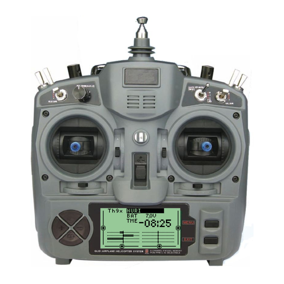
- Page 1 Th9x M A N U A L E U R G L E T H 9 X N G...
- Page 2 Author: Thomas Husterer, Josef Glatthaar Version: V1.1 V1.2 Firmware r46 V1.3 Firmware r59 ©2010 Thomas Husterer...
-
Page 3: Table Of Contents
Contents Chapter 1: Introduction Chapter 2: Performance Chapter 3: Menu structure 3.1 Basic concepts .................. 3.2 Main screen ..................3.3 Model-specific Setup ................Model selection 1/7 ................Model basic setup 2/7 ................. Expo function 3/7 ................Expo function Details ................. setup trim values 4/7 ................ - Page 4 5.1 Glider or powered plane with rudder, elevator and aileron ........Assignment of the channels ..............Special control functions: ..............Explanation .................. 5.2 Glider with 4 flaps ................Assignment of the channels: ..............Special control functions: ..............Explanation ................... 5.3 Powered plane with retractable landing gear and landing gear doors ......
-
Page 5: Chapter 1: Introduction
Introduction he remote control Eurgle th9x, also sold under some other labels like Imax, Turborix or Turnigy manufactured by FlySky is a very low cost 2.4GHz radio with impressive hardware-features but with a less convincing firmware. -
Page 6: Chapter 2: Performance
2 Performance Performance 16 model memories two stage mixer allows any combination of input-channels to form output signals adjustable signal delay for each mixer line even with different values for up and down movement 4 pitch curves with 5 or 9 nodes dynamic memory management servo reverse feature and tunable servo range limits expo and dual rate features... -
Page 7: Chapter 3: Menu Structure
Menu structure 3.1 Basic concepts six buttons are available for operator interface. function move to previous menu key left ore move cursor left, or decrease a value move to next menu key right or move cursor right or increase a value move cursor up key up or increase a value... -
Page 8: Main Screen
3 Menu structure There is no undo functionality. If you change a value or remove something by mistake then you have to re-edit the former values manually. Attention!! Values are stored to the EEPROM-Memory with a short time- delay after the last key press. The storage procedure is announced by some buzzer-beeps 3.2 Main screen Screen contents:... -
Page 9: Model-Specific Setup
Trim Change the Trim Values. keys Attention!! the values are evaluated in a non linear manner. move cursor left move cursor right Open menu-set 'Global Setup' LONG or Open menu-set 'Model-specific Setup' reset timer LONG stop timer alarm. 3.3 Model-specific Setup This set of menus does handle any settings which are related to one unique model. -
Page 10: Model Basic Setup 2/7
3 Menu structure function Select memory slot by cursor movement. cycle to next menu back to main screen select current line for edit commands.(model name is blinking) move current line up or down. duplicate the selected model into next free memory-slot. 3.3.2 Model basic setup 2/7 In edit field 'Name' you can change the model name. -
Page 11: Expo Function
move cursor up and down move cursor left right change values oder reset cursor to the upper right edge leave this menu cycle to the next menu Remove this model memory. Only valid if Cursor is positioned at RM. LONG 3.3.3 Expo function 3/7 In this menu you can set up an exponential behavior for each of the four sticks. -
Page 12: Expo Function Details
3 Menu structure 3.3.4 Expo function Details You can change the two expo values and the expo switch in this menu. In the diagram you see the shape of the expo function. 3.3.5 setup trim values 4/7 Here you can swap the trim values to a base value. After this operation, the trim val- ues in the main screen are repositioned to zero. -
Page 13: Mixer 5/7
3.3.6 Mixer 5/7 This menu is the most important menu of the whole arrangement. You can combine here several Inputs like stick values, pots-values or constants into each one of the output channels. Additionally there are four Helper channels which are used as tem- porary values X1-X4. -
Page 14: Edit Mixer
3 Menu structure 3.3.7 Edit Mixer In this menu you can adjust all the details of one single mixer line. SRC: select the input channel RUD, THR, ELE, AIL, P1, P2, P3, X1, X2, X3, X4, MAX FUL. with MAX you can emit a constant value 0 or +100% with FUL you can emit a constant value -100% or +100% PRC: weight from -125% to +125% CURVE: one of eight curve types. -
Page 15: Curve 6/7
3.3.8 Curve 6/7 3.3.9 Edit Curve function move cursor up / down change value. select predefined curve. This is only valid if cursor is at PRESET leave menu 3.3.10 Limits 7/7 In this menu you can revert output channels and you set up the output value limits. -
Page 16: Global Setup, Diagnosis And Calibrating
3 Menu structure function move cursor up / down move cursor to a column. change value. reset cursor to the upper right edge leave menu cycle to the next menu 3.4 Global setup, diagnosis and calibrating In this group of menus is combined any setups that are not model specific. The menus are numbered as well and can be cycled with the left and right keys as the group above. -
Page 17: Global Setup Ii (Options)
A switch which is used to control the lcd-back light. Attention! This feature requires a hardware extension.. The mode selection is used to assign a specific function to any input stick. At the end it changes the labels which are shown in all other menus where input values are selected. -
Page 18: Software Version
3 Menu structure trainer and student values are both added and then used as input signal only the student controls this channel the students values are weighted by this value this is the channel number which is received from the students radio. -
Page 19: Diagnosis Of Analogue Inputs And Calibrating Of Battery Voltage Measurement
Show the current levels of any key,switch or trim-switch function leave this menu cycle to the next menu 3.4.6 Diagnosis of Analogue inputs and calibrating of battery voltage measurement Shows the values of all analogue inputs with 10 bit resolution. The stick-values are also shown in %. - Page 20 3 Menu structure With the help of this menu you can calibrate the values of all four sticks in a four step procedure. The procedure requires moving the sticks to a given position and then press cursor down while holding the sticks in this position .. function move cursor to SetMid move all sticks into the center-position and hold them...
-
Page 21: Chapter 4: Function
Function 4.1 Power on sequence During power on sequence some important tests are executed. First the EEPROM data is loaded and verified. In case of fault a warning is given and the whole EEPROM is formatted. After this it is checked if free memory is enough to store at least one additional model memory. -
Page 22: Calibrating
4 Function RUD THR P1, P2, P3 Switches ELE AIL Calibration Expo Trim Mixer CH1-CH8 Limit Sender Data-flow Diagram: 4.2.1 Calibrating This first block changes the 10bit AD-value into a symmetrical value from -512 up to +511. It is guaranteed that the center position of the sticks leads to the value 0. Potentiometer-values are handled according to this. - Page 23 y = f(x) = x^k with 1<=k<=3 This diagram shows both curves, the polynomial and the original expo-function in a blue colored line. The lines in red show the derivation of the blue line. Therefore you can recognize the sensitivity of the stick at several working positions.. The polynomial was used in the implementation because we can evaluate it without usage of any floating point arithmetic's.
-
Page 24: Trim
4 Function 4.2.3 Trim This block adds the current trim-value to the associated input value.. This trim value is generated by pressing the trim-keys. The range of this trim -value is -31 to +31. This value is directly shown in the graphical representation in the main screen. -
Page 25: Limits
4.2.6 Limits Before this output values are sent to the receiver, they are checked against the max- imum limitations given by the limits menu. Additionally each channel can become reversed. 4.3 Trainer mode To use trainer mode, we need two separate radios..One radio works as a students radio and the other works as a trainer radio Please note that the students radio must have the power-button switched off.. -
Page 26: Fuse Bits
4 Function 4.4.2 Fuse Bits When you reload the firmware you do not need to change the fuses in any way. If this does happen I have listed my original values: sig=1e,96,02,ff Atmel AVR ATmega64 Lock Bits: 0xff 0b11111111 Fuses low: 0x0e 0b00001110 Fuses high: 0x89 0b10001001 Fuses ext: 0xff 0b11111111 4.5 LCD Back light In rcline-forum its described how to install an EL-Back light behind the LCD-Display see here: http://www.rclineforum.de/forum/thread.php? - Page 27 the inverter. The FET remains the same. In the picture you see a yellow cable which connects to the PB7 of the controller.
-
Page 28: Chapter 5: Programming Examples
5 Programming examples Programming examples Basics: Unlike other radios, there are no ready-mixed programs (Plane, Heli). This makes the programming more complex, but less restrictive. The solution shown here is very flexible. However, setting the model with the desired functions may take a little more thought, but the system is very easily understood. -
Page 29: Explanation
5.1.3 Explanation The control functions RUDder, ELEvator and THRottle are transferred 1:1 to the outputs 1, 2 and 5.. P1 (airbrakes) will output both channel 3 as well as 4. Here only positive values are taken into account because otherwise the negative values of P1 would result in flaps movement into the wrong direction. -
Page 30: Special Control Functions
5 Programming examples Channel 4: flaps left inboard Channel 5: Aileron right outside Channel 6: flaps right inboard 5.2.2 Special control functions: Inboard flaps shall be used as airbrakes and for aileron assistance The outer and inner flaps are to be placed on different positions (high speed, thermal flight ...) selected by a switch. -
Page 31: Powered Plane With Retractable Landing Gear And Landing Gear Doors
Channel 1: Rudder 1:1 Stick Rudder Channel 2: Elevator 1:1 Stick Elevator 25% when airbrakes are active; this is delayed by Curve1 and the speed-settings Channel 3: Aileron left outside 1:1 Stick Aileron -50% Butterfly inverse 10% P1 during flight-mode (RUD-switch) Channel 4: flaps left inboard When THR is set then the flaps are deployed slowly... -
Page 32: Helicopter With 120° Swash Plate And Pitch
5 Programming examples 5.5 Helicopter with 120° Swash Plate and Pitch -36% 50% of 1 86% of 1 like 2 -36% 50% of 1 -62% like 4 like 2 5.6 Phase switch As in Example 5.2.2 this can be setup by a switch, in conjunction with a poten- tiometer or a fixed value, an offset can be added on each channel.
Need help?
Do you have a question about the Eurgle th9x and is the answer not in the manual?
Questions and answers