Sony LMD-2451MD Instructions For Use Manual
Hide thumbs
Also See for LMD-2451MD:
- Manual (303 pages) ,
- Specification sheet (4 pages) ,
- Instructions for use manual (175 pages)

Related Manuals for Sony LMD-2451MD


Summary of Contents for Sony LMD-2451MD
-
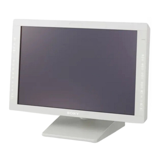
Page 1: Lcd Monitor
4-171-242-14 (1) LCD Monitor Instructions for Use Before operating the unit, please read this manual thoroughly and retain it for future reference. LMD-2451MD © 2009 Sony Corporation... - Page 2 WARNING Indications for Use/Intended Use The Sony LMD-2451MD LCD Monitor is intended to To reduce the risk of fire or electric shock, do provide color video displays of images from surgical not expose this apparatus to rain or moisture.
- Page 3 refer to the addresses provided in the separate service or If you have questions on the use of the above Power guarantee documents. Cord / Appliance Connector / Plug, please consult a qualified service personnel. Symbols on the unit WARNING on power connection for medical Symbol Location This symbol indicates...
- Page 4 LMD-2451MD. Guidance and manufacturer’s declaration-electromagnetic emissions The LMD-2451MD is intended for use in the electromagnetic environment specified below. The customer or the user of the LMD-2451MD should assure that it is used in such an environment. Emission test Compliance...
- Page 5 Guidance and manufacturer’s declaration - electromagnetic immunity The LMD-2451MD is intended for use in the electromagnetic environment specified below. The customer or the user of the LMD- 2451MD should assure that it is used in such as environment. IEC 60601 test...
- Page 6 Guidance and manufacturer’s declaration - electromagnetic immunity The LMD-2451MD is intended for use in the electromagnetic environment specified below. The customer or the user of the LMD- 2451MD should assure that it is used in such as environment. IEC 60601 test...
- Page 7 Recommended separation distances between portable and mobile RF communications equipment and the LMD- 2451MD The LMD-2451MD is intended for use in an electromagnetic environment in which radiated RF disturbances are controlled. The customer or the user of the LMD-2451MD can help prevent electromagnetic interference by maintaining a minimum distance between portable and mobile RF communications equipment (Transmitters) and the LMD-2451MD as recommended below, according to the maximum output power of the communications equipment.
-
Page 8: Table Of Contents
Table of Contents Precaution .............. 9 On Safety ............9 On Installation ............ 9 About the LCD Display Panel ......9 On Burn-in ............9 On a Long Period of Use ........9 On Cleaning ............9 Disposal of the Unit ......... 10 Recommendation to Use more than One Unit ................. -
Page 9: Precaution
the monitor becomes warm, the screen returns to Precaution normal. • The screen and the cabinet become warm during operation. This is not a malfunction. On Safety On Burn-in • Operate the unit on 100-240 V AC only. • The nameplate indicating operating voltage, etc. is For LCD panel, permanent burn-in may occur if still located on the AC adaptor. -
Page 10: Disposal Of The Unit
The finish of the surface images. Sony recommends that all viewers take may deteriorate or the coating may come off. regular breaks while watching video images. The length and frequency of necessary breaks will vary from person to person. -
Page 11: On Simultaneous Use With A Radio Knife, Etc
nausea, or motion sickness) can be provoked by such Features factors as quick movements or shakiness of video picture, focal position of video pictures, distance between objects and image capturing modules, user’s point of gaze in video pictures, other varying Compliance with medical safety conditions of video pictures to be input to this device, standards in U.S.A., Canada and Europe... - Page 12 The number of the DVI input connectors can be Aspect setting increased by installing the optional input adaptor into You can set the monitor to 4:3 or 16:9 display mode the optional input port. according to the input signal. To view more than SXGA signals when the DVI input is Scan function selected, use the cable within 3 m (118 inches) in...
-
Page 13: Location And Function Of Parts And Controls
Location and Function of Parts and Controls Front Panel COMPOSITE COMPONENT – – – HD15 – – USER MEM a Tally lamp Adjusts the color intensity. You can check the status of the monitor by the color of Press the + button to increase the color intensity or the – the tally lamp. -
Page 14: Input Select Buttons
j Input select buttons Press the button to monitor the signal input to each connector. A-1, A-2, B-1 and B-2 buttons are used when an optional input adaptor has been installed in the option port. COMPOSITE button: to monitor the signal through the COMPOSITE IN connector Y/C button: to monitor the signal through the Y/C IN connector... -
Page 15: Input Signals And Adjustable/Setting Items
Input Signals and Adjustable/Setting Items Input signal Item Video* B & W* Component* RGB* Computer Y/C* DVI* HD15 CONTRAST* BRIGHT* CHROMA* × × PHASE* (NTSC) APERTURE COLOR TEMP COLOR SPACE AUTO CHROMA/ × × × × × × × × PHASE ×... -
Page 16: Rear/Bottom Panel
Rear/Bottom Panel 3 4 5 6 7 qd qf /I (Equipotential/Function Earth) terminal To use the external sync signal, press the function button (equipotential) terminal that EXT SYNC is assigned (F1 button at the factory Connects the equipotential plug. setting). I (function earth) terminal Connects the earth cable. - Page 17 o DVI-D input connector (DVI-D) (power) switch The power is turned on or off. Inputs DVI Rev.1.0 applicable digital RGB signal. The monitor is turned on by pressing side To view the signals of the SXGA and higher resolution when the DVI input is selected, use the cable within 3 m l PARALLEL REMOTE connector (modular (118 inches) in length.
-
Page 18: Connecting The Ac Power Cord
Insert the DC IN connector into the DC 5V/24V IN Connecting the AC connector on the bottom of this unit until it locks. Power Cord Connect the supplied AC power cord as illustrated. Two kinds of AC plug holders are supplied with this unit. -
Page 19: Installing The Input Adaptor
Installing the Input Removing the Adaptor Connector Cover Before installing the input adaptor, disconnect the power When the unit is shipped from the factory, a connector cord. cover is attached to the PARALLEL REMOTE connector and the SERIAL REMOTE connector (RJ- Remove the panel of the optional input port. -
Page 20: Selecting The Default Settings
Selecting the Default Settings When you turn on the unit for the first time after – purchasing it, select the area where you intend to use this – unit from among the options. – The default setting values for each area –... -
Page 21: Selecting The Menu Language
2 If LATIN AMERICA is selected: Selecting the Menu PAL&PAL-N area Language L A T I N A M E R I C A P A L & P A L - N A R E A Argentina A R G E N T I N A P A R A G U A Y Paraguay U R U G U A Y... -
Page 22: Using The Menu
The setting items (icons) in the selected menu are Using the Menu displayed in yellow. USER CONFIG – SYSTEM SETTING The unit is equipped with an on-screen menu for making M AT R I X : C O M P O N E N T L E V E L : xxxx various adjustments and settings such as picture control, N T S C S E T U P :... - Page 23 The menu icon presently selected is shown in About the memory of the settings yellow and setting items are displayed. The settings are automatically stored in the monitor memory. USER CONFIG – SYSTEM SETTING M AT R I X : C O M P O N E N T L E V E L : xxxxx N T S C S E T U P :...
-
Page 24: Loading User Memory
Loading USER MEMORY Adjustment Using the Menus You can load the picture settings saved in the USER MEMORY menu (on page 33). Items The screen menu of this monitor consists of the COMPOSITE following items. COMPONENT – STATUS (the items indicate the –... -
Page 25: Adjusting And Changing The Settings
MATRIX For the video input COMPONENT LEVEL NTSC SETUP STATUS 1/2 GAMMA F O R M AT xxxxxxxxx FORMAT DISPLAY xxxxxxxx LANGUAGE C O L O R T E M P POWER SAVING C O M P O N E N T L E V E L xxxxx I/P MODE N T S C S E T U P... -
Page 26: Color Temp/Space Menu
COLOR TEMP/SPACE menu For the video input The COLOR TEMP/SPACE menu is used for adjusting the picture white balance or color space. USER CONTROL 1/3 You need to use the measurement instrument to adjust AU T O C H R O M A / P H A S E the white balance. - Page 27 For the DVI/HD15 input Submenu Setting SUB CONTROL Adjusts finely the adjustment range * The 1/3 menu cannot be adjusted. of the button on the front panel for CONTRAST, BRIGHTNESS, CHROMA and PHASE. USER CONTROL 2/3 • CONTRAST: Adjusts the picture S U B C O N T R O L contrast.
-
Page 28: User Config Menu
USER CONFIG menu Submenu Setting The USER CONFIG menu is used for setting the PICTURE CONTROL Adjusts to monitor the picture more clearly. system, multi display, function button, computer detect • SIZE H: Adjusts the horizontal and option DVI. size of the picture. The higher the setting, the larger the horizontal size of the USER CONFIG... -
Page 29: Power Saving
MULTI DISPLAY SETTING Submenu Setting LANGUAGE Selects the menu or message language from among seven USER CONFIG MULTI DISPLAY SETTING languages. M U LT I D I S P L AY E N A B L E : • ENGLISH: English M U LT I D I S P L AY: •... -
Page 30: Function Button Setting
About the function assigned to the Submenu Setting function button SUB INPUT Sets the input signal of the sub display. SELECT You can select from among SCAN COMPOSITE, Y/C, RGB, COMPONENT, DVI, HD15, OPTION Press to change the scan size of the picture. Press to A-1, OPTION A-2, OPTION B-1, switch between NORMAL scan (0% scan), OVER scan OPTION B-2, VIDEO WAVE and OFF. -
Page 31: I/P Mode
Scan mode image Note If the APA operation does not finish correctly depending on the input signal, adjust DOT PHASE (page 28). I/P MODE Press the button to set the delay by the picture processing to the minimum level when interlace signal is input. -
Page 32: Remote Menu
REMOTE menu Submenu Setting COMPUTER The appropriate preset memory is set for REMOTE DETECT the signal from DVI and HD15 input PA R A L L E L R E M O T E : connector. Select “PRESET1” for the standard computer signal. -
Page 33: Key Inhibit Menu
USER MEMORY menu Submenu Setting MONITOR Set the monitor setting. IP ADDRESS: Sets the IP U S E R M E M O RY 1 / 3 address. x0 1 U S E R 0 1 SUBNET MASK: Sets the ·... - Page 34 To save the picture setting Press the – button to select “NAME”, then press the ENTER button. Press the + or – button to select the memory number The menu for setting the user name appears. in the USER MEMORY menu, then press the ENTER button.
-
Page 35: Troubleshooting
Troubleshooting Specifications Picture performance This section may help you isolate the cause of a problem and as a result, eliminate the need to contact technical LCD panel a-Si TFT Active Matrix support. Pixel efficiency 99.99% • The display is colored in green or purple t Select Viewing angle (panel specification) the correct input by pressing RGB or COMPONENT 89°/89°/89°/89°... - Page 36 Temperature Always verify that the unit is operating properly before 0 °C to 35 °C (32 °F to 95 °F) use. SONY WILL NOT BE LIABLE FOR Recommended temperature DAMAGES OF ANY KIND INCLUDING, BUT 20 °C to 30 °C (68 °F to 86 °F)
-
Page 37: Pin Assignment
Pin assignment Available signal formats The unit is applicable to the following signal formats. PARALLEL REMOTE connector For details on the input signal available for HD15, DVI Modular connector and BKM-256DD, see page 38. (8-pin) Composite BKM- BKM- BKM- Pin number Functions System Component... - Page 38 Available HD15/DVI/BKM-256DD input signal format About the preset signal This unit has a preset memory for signals connected to the HD15 and DVI input connectors, and BKM-256DD. When a preset signal is input, the unit automatically detects the signal type and recalls the data for the signal from the preset memory to adjust it to an optimum picture.
- Page 39 Sync. polarity Dot clock Resolution [MHz] [kHz] [Hz] Horizontal Vertical 1920 × 1080 60 Hz 138.625 66.647 59.988 Positive Negative 1280 × 1024 60 Hz 91.000 63.194 59.957 Positive Negative 1280 × 768 50 Hz 65.125 39.518 49.959 Negative Positive 1280 ×...
- Page 40 PRESET 5 PRESET 7 (Selected using DVI in the menu) Preset signal [kHz] [Hz] Preset signal [kHz] [Hz] 640 × 480 31.5 HD15 1422 × 1064 33.75 800 × 600 31.3 712 × 480 15.734 DVI/ 800 × 600 46.9 BKM-256DD 704 ×...
- Page 41 Sync. polarity Dot clock Resolution [MHz] [kHz] [Hz] Horizontal Vertical 1280 × 1024 60 Hz 91.000 63.194 59.957 Positive Negative 1280 × 768 60 Hz 80.125 47.693 59.992 Negative Positive 1280 × 768 60 Hz 68.250 47.396 59.995 Positive Negative PRESET 2 PRESET 4 Preset signal...
- Page 42 PRESET 6 Preset signal Signal standards 576/50P ITU-R BT.1358 480/60P SMPTE-293M 1080/50I SMPTE-274M SMPTE-260M/BTA 1035/60I HD15 S-001B SMPTE-274M/BTA 1080/60I S-001B 720/60P SMPTE-296M 720/50P SMPTE-296M 576/50P ITU-R BT.1358 480/60P SMPTE-293M 1080/50I SMPTE-274M SMPTE-260M/BTA DVI/ 1035/60I S-001B BKM-256DD SMPTE-274M/BTA 1080/60I S-001B 720/60P SMPTE-296M 720/50P SMPTE-296M...
-
Page 43: Dimensions
Side Dimensions When an optional stand SU-560 is attached Front 110 (4 When an optional stand SU-560 is attached 602.4 (23 COMPOSITE CONTROL COMPONENT CONTRAST – PHASE – CHROMA – HD15 BRIGHT – MENU – ENTER 302 (12) USER MEM RETURN Mass Approx. - Page 44 Sony Corporation...
Need help?
Do you have a question about the LMD-2451MD and is the answer not in the manual?
Questions and answers