
Related Manuals for Future light MH-660


Summary of Contents for Future light MH-660
- Page 1 BEDIENUNGSANLEITUNG USER MANUAL Version 2.0 © Copyright Für weiteren Gebrauch aufbewahren! Keep this manual for future needs! Nachdruck verboten! Reproduction prohibited!
- Page 2 FUTURELIGHT DOMINATOR MKII centre-piece 51832603 FUTURELIGHT MH-640 Moving-Head Washlight 51833000 FUTURELIGHT MH-640 Moving-Head silver Washlight 51833010 FUTURELIGHT MH-660 Moving-Head Spot 51833020 FUTURELIGHT MH-660 Moving-Head silver Spot 51833030 FUTURELIGHT MH-860 Moving-Head Spot 51833060 FUTURELIGHT MH-860 Moving-Head silver Spot 51833065 FUTURELIGHT CONTROLLER FUTURELIGHT CONTROLLERS...
-
Page 3: Table Of Contents
Inhaltsverzeichnis Einführung..........................4 Features ..........................4 Geräteübersicht .......................5 Sicherheit ...........................6 Sicherheitshinweise ......................6 Bestimmungsgemäße Verwendung.................6 Installation..........................8 Einsetzen/Wechseln der Lampe ..................8 Installation einer optionalen Linse..................9 Einsetzen/Austauschen von Gobos ................10 Projektormontage ......................11 Anschluss an den DMX-512 Controller / Verbindung Projektor - Projektor....13 DMX-Protokoll ........................15 Funktionen der Steuerkanäle..................15 Funktionen der Steuerkanäle - 8 Bit-Protokoll: ..............17 Adressierung des Projektors ..................17 Fernsteuerbare Funktionen ....................18... -
Page 4: Einführung
LESEN SIE VOR DER ERSTEN INBETRIEBNAHME ZUR EIGENEN SICHERHEIT DIESE BEDIENUNGSANLEITUNG SORGFÄLTIG DURCH! Einführung Wir freuen uns, dass Sie sich für einen FUTURELIGHT MH-660 entschieden haben. Sie haben hiermit ein intelligens, leistungsstarkes und vielseitiges Beleuchtungssystem erworben. Nehmen Sie den FUTURELIGHT MH-660 aus der Verpackung. -
Page 5: Geräteübersicht
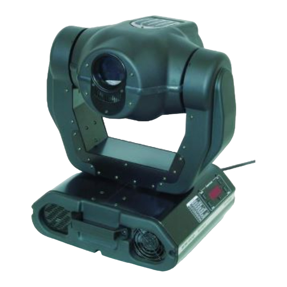
Geräteübersicht 1 - Projektorkopf 2 - Aufhängung 3 - Tragegriffe 4 - Base 5 - Base - Seite 6 - Steuereinheit Base - Seite: 7 - DMX-Ausgang 8 - DMX-Eingang 9 - Netzanschluss 10 - Sicherungshalter 11 - Netzschalter Control Board: 12 - Mode-Taste 13 - Display 14 - Enter-Taste... -
Page 6: Sicherheit
Sicherheit Sicherheitshinweise ACHTUNG! Seien Sie besonders vorsichtig beim Umgang mit gefährlicher Netzspannung. Bei die- ser Spannung können Sie einen lebensgefährlichen elektrischen Schlag erhalten! Dieses Gerät hat das Werk in sicherheitstechnisch einwandfreiem Zustand verlassen. Um diesen Zustand zu erhalten und einen gefahrlosen Betrieb sicherzustellen, muss der Anwender die Sicherheitshinweise und die Warnvermerke unbedingt beachten, die in dieser Bedienungsanleitung enthalten sind. - Page 7 Dieses Gerät ist für professionelle Anwendungen, z. B. auf Bühnen, in Diskotheken, Theatern etc. vorgesehen. Lichteffekte sind nicht für den Dauerbetrieb konzipiert. Denken Sie daran, dass konsequente Betriebspausen die Lebensdauer des Gerätes erhöhen. Das Gerät darf niemals ohne Lampe in Betrieb genommen werden! Vermeiden Sie Erschütterungen und jegliche Gewaltanwendung bei der Installation oder Inbetriebnahme des Gerätes.
-
Page 8: Installation
Installation Einsetzen/Wechseln der Lampe LEBENSGEFAHR! Lampe nur bei ausgeschaltetem Gerät einsetzen! Netzstecker ziehen! 2 Kreuzschlitzschrauben 2 Kreuzschlitzschrauben Oberseite Unterseite Unterseite Zum Einsetzen der Lampe (MSD 230 V/250 W oder MSD 230 V/200 W) öffnen Sie den Gehäusedeckel des Kopfes wie in oben stehender Zeichnung. Lösen Sie dazu die Kreuzschlitzschrauben an der Vorder- und Rückseite des Gehäusedeckels. -
Page 9: Installation Einer Optionalen Linse
Lampenjustierung RICHTIG FALSCH Optimalen Abstand zur Linse einhalten! Optimaler Abstand 1-1,5 mm Schraube "A" Schraube "B" Der Lampenhalter des Gerätes wird ab Werk justiert. Da sich die zu verwendenden Lampen von Hersteller zu Hersteller unterscheiden, kann es u. U. notwendig sein, die Position des Lampenhalters nachzujustieren. Die Lampe muss z. -
Page 10: Einsetzen/Austauschen Von Gobos
Optionale 18°-Linse: Lösen Sie die Rändelschraube an dem Blech des Lichtaustritts. Setzen Sie die optionale 18°-Linse ein und befestigen Sie sie mit der Rändelschraube. Strahlenverlauf: Standard 15°-Linse Optionale 12°-Linse Optionale 18°-Linse Einsetzen/Austauschen von Gobos LEBENSGEFAHR! Gobos nur bei ausgeschaltetem Gerät austauschen Netzstecker ziehen! Öffnen Sie den Gehäusedeckel des Kopfes, indem Sie die Kreuzschlitzschrauben an der Vorder- und Rückseite des Gehäusedeckels lösen. -
Page 11: Projektormontage
Rotierendes Goborad: ACHTUNG! Niemals die Schrauben der rotierenden Gobos lösen, da ansonsten die Kugellager geöffnet werden! Entfernen Sie den Sprengring mit einem geeigneten Werkzeug. Entnehmen Sie das Gobo und setzen Sie das neue Gobo ein. Drücken Sie den Sprengring zusammen und setzen Sie ihn vor das Gobo. Projektormontage LEBENSGEFAHR! Bei der Installation sind insbesondere die Bestimmungen der BGV C1 (vormals VBG 70) - Page 12 Wenn der Projektor von der Decke oder hochliegenden Trägern etc. abgehängt werden soll, muss immer mit Traversensystemen gearbeitet werden. Der Projektor darf niemals frei schwingend im Raum befestigt werden. Achtung: Projektoren können beim Herabstürzen erhebliche Verletzungen verursachen! Wenn Sie Zweifel an der Sicherheit einer möglichen Installationsform haben, installieren Sie den Projektor NICHT! Vergewissern Sie sich vor der Montage, dass die Montagefläche mindestens die 10-fache Punktbelastung des Eigengewichtes des Projektors aushalten kann.
-
Page 13: Anschluss An Den Dmx-512 Controller / Verbindung Projektor - Projektor
Sicherheitsfangseil Haken Anschluss ans Netz Schließen Sie das Gerät über den Netzstecker ans Netz an. Die Belegung der Anschlussleitungen ist wie folgt: Leitung International Braun Außenleiter Blau Neutralleiter Gelb/Grün Schutzleiter Der Schutzleiter muss unbedingt angeschlossen werden! Lichteffekte sollten im Allgemeinen nicht über Dimmerpacks geschaltet werden. LEBENSGEFAHR! Vor der ersten Inbetriebnahme muss die Einrichtung durch einen Sachverständigen geprüft werden! Anschluss an den DMX-512 Controller / Verbindung Projektor - Projektor... - Page 14 Achten Sie darauf, dass die Adern der Datenleitung an keiner Stelle miteinander in Kontakt treten. Die Geräte werden ansonsten nicht bzw. nicht korrekt funktionieren. Die Verbindung zwischen Controller und Projektor sowie zwischen den einzelnen Geräten muss mit einem zweipoligen geschirmten Kabel erfolgen. Die Steckverbindung geht über 3-polige XLR-Stecker und - Kupplungen.
-
Page 15: Dmx-Protokoll
DMX-Protokoll Funktionen der Steuerkanäle Steuerkanal 1 - Drehbewegung (Pan) Wenn Sie den Regler verschieben, bewegen Sie den Kopf horizontal (PAN). Allmähliches Einstellen des Kopfes bei langsamen Schieben des Reglers (0-255, 128-Mitte). Der Kopf lässt sich um 530° drehen und kann in jeder gewünschten Position angehalten werden. - Page 16 Offen/weiß Türkis Cyan Grün Magenta Hellblau Gelb Grün Pink Blau Orange 128 - 190 Rainboweffekt vorwärts mit absteigender Geschwindigkeit 191 - 192 Keine Rotation 193 - 255 Rainboweffekt rückwärts mit zunehmender Geschwindigkeit Steuerkanal 8 - Ohne Funktion Steuerkanal 9 - Prismenrad 0 - 95 Offen 96 - 255...
-
Page 17: Funktionen Der Steuerkanäle - 8 Bit-Protokoll
Werden mehrere MH-660 auf eine Adresse definiert, arbeiten sie synchron. Vorgehensweise: 1. Schalten Sie den MH-660 ein und warten Sie, bis das Gerät den Setup beendet hat (auf dem Display blinkt „rSt“). 2. Drücken Sie die Mode-Taste, um in das Hauptmenü zu gelangen. Über die Up- und Down-Tasten können Sie sich durch das Menü... -
Page 18: Fernsteuerbare Funktionen
Fernsteuerbare Funktionen Lampe Der MH-660 wird mit einer MSD 230 V/250 W GY-9,5 oder MSD 230 V/200 W GY-9,5 Lampe betrieben. Ein Relais im Projektor ermöglicht die Schaltung der Lampe über das Control Board am Projektorkopf oder über den angeschlossenen Controller. -
Page 19: Dimmer / Shutter / Strobe
Lichtaustritt stufenlos von 0-100 % dimmen. Lüfter Der MH-660 wird über zwei Axiallüfter im Projektorkopf und einen in der Base gekühlt. Die Lüfter- geschwindigkeit (und damit natürlich auch das Geräusch) kann stufenlos geregelt werden und lässt sich für leise Vorführungen auf ein Minimum reduzieren. -
Page 20: Spec - Spezialfunktionen
Mit dieser Funktion können Sie das Demonstrationsprogramm des Projektors aktivieren. So lassen sich einige der Möglichkeiten des MH-660 ohne externen Controller vorführen. Drücken Sie die Up-/Down- Tasten, um die Sequenzen „Mod1“ oder „Mod2“ auszuwählen. Die Sequenzen unter „Mod1“ eignen sich besonders für Projektionen an der Wand, Decke oder auf dem Boden, ohne dass der Kopf sich bewegt. - Page 21 - Automatische Lampenschaltung Mit dieser Funktion kann das Gerät so programmiert werden, dass die Lampe automatisch zündet, sobald Sie das Gerät einschalten. Wenn die Lampe automatisch gezündet werden soll, wählen Sie über die Up- /Down-Tasten "ON" aus oder "OFF", wenn die Lampe ausgeschaltet sein soll. Drücken Sie die Enter-Taste, um die Auswahl zu bestätigen oder die Mode-Taste, um diesen Modus zu verlassen.
- Page 22 - Lüftergeschwindigkeit niedrig/Lampenabschaltung Die Lüftergeschwindigkeit bleibt so lange niedrig, bis die Innentemperatur des Projektors den Maximalwert überschritten wird. Der Projektor schaltet dann automatisch die Lampe ab. - Voreinstellungen Mit dieser Funktion lassen sich alle Individualdaten des Projektors auf die Voreinstellungen ab Werk zurücksetzen.
-
Page 23: Fehlermeldungen
DMX Kalibrierungsprotokoll: Nachdem Sie die benötigten Funktionen kalibriert haben und mit der Enter-Taste bestätigt haben, muss die Funktion „ArES“ gewählt werden, um die eingestellten Werte in das EEPROM zu übertragen und einen Reset auszuführen. Fehlermeldungen Diese Fehlermeldung erscheint, wenn Sie versuchen, die Lampe zu zünden bevor die 5 Minuten Abkühlzeit verstrichen sind. -
Page 24: Technische Daten
Diese Fehlermeldung bedeutet, dass das Gerät überhitzt ist (was bei 45° C oder mehr der Fall sein kann) und das Relais die Lampe abgeschaltet hat. Diese Meldung bleibt solange im Display, bis die Temperatur sich auf ein unkritisches Niveau gesenkt hat. Danach erscheint „HEAt“, um anzuzeigen, dass die Lampe noch zu heiß... - Page 25 Elektronik - Digitaler Serieneingang DMX-512 - 14/16 Steuerkanäle (je nach Auflösung) Steuerkanäle Steuerkanal 1 - Drehbewegung (Pan) Steuerkanal 2 - Kippbewegung (Tilt) Steuerkanal 3 - Pan 16 Bit Steuerkanal 4 - Tilt 16 Bit Steuerkanal 5 - Pan / Tilt Geschwindigkeit Steuerkanal 6 - Lampe, Reset, Lüfter Steuerkanal 7 - Farben Steuerkanal 8 - Ohne Funktion...
-
Page 26: Reinigung Und Wartung
Reinigung und Wartung Der Unternehmer hat dafür zu sorgen, dass sicherheitstechnische und maschinentechnische Einrichtungen mindestens alle vier Jahre durch einen Sachverständigen im Umfang der Abnahmeprüfung geprüft werden. Der Unternehmer hat dafür zu sorgen, dass sicherheitstechnische und maschinentechnische Einrichtungen mindestens einmal jährlich durch einen Sachkundigen geprüft werden. Dabei muss unter anderem auf folgende Punkte besonders geachtet werden: 1) Alle Schrauben, mit denen das Gerät oder Geräteteile montiert sind, müssen fest sitzen und dürfen nicht korrodiert sein. -
Page 27: Anhang
Sollten Sie noch weitere Fragen haben, steht Ihnen Ihr Fachhändler jederzeit gerne zur Verfügung. Anhang Wir wünschen Ihnen mit Ihrem FUTURELIGHT MH-660 viel Spaß. Wenn Sie sich an die Anweisungen der vorliegenden Bedienungsanleitung halten, versichern wir Ihnen, dass Ihnen das Gerät lange viel Freude bereiten wird. - Page 28 Table of contents Introduction ........................29 Features ........................29 Beampath ........................29 Description of the fixture ....................30 Safety ..........................31 Safety instructions ......................31 Operating determinations ....................31 Installation........................32 Fitting/Exchanging the lamp ..................32 Installation of an optional lens ..................34 Inserting/Exchanging gobos ..................35 DMX-512 connection / connection between fixtures ............38 DMX-Protocol ........................39 Function of the control channels - 16 bit protocol ............39 Function of the control channels - 8 bit protocol: ............41...
-
Page 29: Introduction
FOR YOUR OWN SAFETY, PLEASE READ THIS USER MANUAL CAREFULLY BEFORE YOU INITIAL START - UP! Introduction Thank you for having chosen a FUTURELIGHT MH-660. You acquired a versatile, powerful and intelligent lighting-effect. Unpack your FUTURELIGHT MH-660 and make sure that there are no damages caused by transportation. -
Page 30: Description Of The Fixture
Description of the fixture 1 - Projector-head 2 - Yoke 3 - Carring handles 4 - Base 5 - Base - side panel 6 - Control Board Base - side panel: 7 - DMX-output 8 - DMX-input 9 - Powercord 10 - Fuseholder 11 - Power-switch Control Board:... -
Page 31: Safety
Safety Safety instructions CAUTION! Be careful with your operations. With a dangerous voltage you can suffer a dangerous electric shock when touching the wires! This device has left our premises in absolutely perfect condition. In order to maintain this condition and to ensure a safe operation, it is absolutely necessary for the user to follow the safety instructions and warning notes written in this user manual. -
Page 32: Installation
Never run the device without lamp! Do not shake the device. Avoid brute force when installing or operating the device. Never lift the fixture by holding it at the projector-head, as the mechanics may be damaged. Always hold the fixture at the transport handles. When choosing the installation-spot, please make sure that the device is not exposed to extreme heat, moisture or dust. - Page 33 2 Phillips screws 2 Phillips screws Top cover Bottom cover Bottom cover To insert the lamp MSD 230 V/250 W or MSD 230 V/200 W open the top cover of the head (see the drawings to identify which cover is top) by loosening the 4 Phillips screws on the front and rear sides of the top cover.
-
Page 34: Installation Of An Optional Lens
Screw "A" Screw "B" The MH-660 lampholder is aligned at the factory. Due to differences between lamps, fine adjustment may improve light performance. Strike the lamp and focus the light on a flat surface (wall). As the optimum distance of lamp from lens was adjusted during the installing or changing the lamp (by turning the screw "A"), it is necessary to adjust only... -
Page 35: Inserting/Exchanging Gobos
Optional 18°-lens: Unscrew the knurled-head screw on the plate of the light-output. Install the optional 18°-lens and fix it with the knurled-head screw. Inserting/Exchanging gobos DANGER! Install the gobos with the device switched off only. Unplug from mains before! To insert the gobos open the top cover of the head by loosening the 4 Phillips screws on the front and rear sides of the top cover. - Page 36 Rigging DANGER TO LIFE! Please consider the EN 60598-2-17 and the respective national norms during the installation! The installation must only be carried out by an authorized dealer! The installation of the projector has to be built and constructed in a way that it can hold 10 times the weight for 1 hour without any harming deformation.
- Page 37 The Moving-Head can be placed directly on the stage floor or rigged in any orientation on a truss without altering its operation characte- ristics (see the drawing). The fixture’s base enables to be mounted in two ways. Use the clamps with screws M10 or M8 - check the base bottom.
-
Page 38: Dmx-512 Connection / Connection Between Fixtures
In general, lighting effects should not be connected to dimming-packs. DANGER TO LIFE! Before taking into operation for the first time, the installation has to be approved by an expert! DMX-512 connection / connection between fixtures The wires must not come into contact with each other, otherwise the fixtures will not work at all, or will not work properly. -
Page 39: Dmx-Protocol
DMX-Protocol Function of the control channels - 16 bit protocol Channel 1 - Horizontal movement (Pan) Push slider up in order to move head horizontally (PAN). Gradual head adjustment from one end of the slider to the other (0-255, 128-center). The head can be turned by 530° and stopped at any position you wish. - Page 40 Channel 7 - Colours Linear colour change following the movement of the slider. In this way you can stop the colour-wheel in any position - also between two colours creating double-coloured beams. Between 128 and 190 and between 193 and 255, the colour-wheel rotates continuously the so-called "Rainbow"...
-
Page 41: Function Of The Control Channels - 8 Bit Protocol
MH-660 will respond to the controller. If you set, for example, the address to channel 5, the MH-660 will use the channel 5 to 20 for control. Please, be sure that you don’t have any overlapping channels in order to control each MH-660 correctly and independently from any other fixture on the DMX data link. -
Page 42: Remotely Controllable Functions
The MH-660 is to be operated with a MSD 230 V/250 W GY-9.5 or MSD 230 V/200 W GY-9.5 lamp. A relay inside of the MH-660 allows you to switch on and off the lamp via the Control Board on the top side or via your controller without affecting the rest of the lighting. -
Page 43: Fan
The MH-660 is cooled by three axial fans - one each in the projector head and one in the base. The speed of the fan (and of course the noise) can be continuously reduced if very quiet performance is required. -
Page 44: Spec -Special Functions
"Mod2" uses all MH-660 functions and therefore is good for a complete introduction of the fixture. - Reset Function Press [Enter] key to run reset. This option enables the MH-660 to index all effects (functions) and return to their standard positions. SPEC -Special functions Use the [Up] and [Down] keys to browse through the special functions and select the one by pressing [Enter]. - Page 45 - low/high speed of the fan operating The fan keeps the adjusted low speed until the temperature exceeds max. inside temp. of the fixture, then the MH-660 automatically switches from low to high fan-speed. - low speed / switch off the lamp operating The fan keeps the adjusted low speed until the temperature exceeds max.
- Page 46 - Default settings Press [Enter] to reset all fixture personalities (not the adjusting functions) to the default values. On the display will appear „rSt” meaning that the fixture makes the reset. See the table of personality setting and their default positions. Personality Display Default values...
-
Page 47: Error And Information Messages
This message appears if you try to switch on the lamp within 5 minutes after having switched it off (the lamp is too hot). The message will appear on the display if the lamp doesn't ignite within 28 seconds. The MH-660 will store this information and automatically ignite the lamp when the 5 minutes period has expired. -
Page 48: Technical Specifications
temperature will be on a suitable level, then the display will show the HEAt message meaning the lamp is too hot (explanation see above). This message appears if the lamp lighting sensor is failed. Please contact your dealer. This message will appear if the fixture was shortly disconnect from the mains. (PAN-yoke movement error) This message will appear after the reset of the fixture if the yoke’s magnetic- indexing circuit malfunction (sensor failed or magnet missing) or the stepping-motor is defective (or its driving IC on the main PCB). - Page 49 Channel 6: Fan speed, On/Off lamp, reset Channel 7: Colours Channel 8: No function Channel 9: Prism-wheel Channel 10: Prism-rotation Channel 11: Rotating gobos Channel 12: Gobo rotation, gobo indexing Channel 13: No function Channel 14: Focus Channel 15: Shutter, strobe Channel 16: Dimmer Pan/Tilt Pan movement range 530°...
-
Page 50: Cleaning And Maintenance
Cleaning and maintenance The operator has to make sure that safety-relating and machine-technical installations are inspected by an expert after every four years in the course of an acceptance test. The operator has to make sure that safety-relating and machine-technical installations are inspected by a skilled person once a year. -
Page 51: Appendix
Should you have further questions, please contact your dealer. Appendix We hope you will enjoy your MH-660. We can assure you that you will enjoy this device for years if you follow the instructions given in this manual. Should you have further questions, do not hesitate to contact your local dealer. - Page 52 Sommaire Introduction ........................53 Features ........................53 Description de l'appareil....................54 Sécurité..........................55 Instructions de sécurité....................55 Emploi selon les prescriptions ..................55 Installation........................57 Installer/remplacer de la lampe..................57 Installation d'une lentille optionelle ................58 Introduire/échanger gobos.....................59 Montage du projecteur....................60 Connexions au contrôleur DMX-512 / raccord projecteur - projecteur ......62 Protocole DMX .........................64 Fonctions des canaux de contrôle .................64 Fonction des canaux de contrôle - protocole 8 bit: ............66...
-
Page 53: Introduction
POUR VOTRE PROPRE SÉCURITÉ, VEUILLEZ LIRE CE MODE D‘EMPLOI ATTENTIVEMENT AVANT LA PREMIÈRE MISE EN SERVICE! Introduction Nous vous remerçions et vous félicitons d’avoir choisi un FUTURELIGHT MH-660. Vous êtes en possession d’un effet lumineux puissant, intelligent et aux possibilités multiples. Sortez le MH-660 de son emballage. -
Page 54: Description De L'appareil
Description de l'appareil 1 - Tête rotatif 2 - Bras rotatifs 3 - Poignée de transport 4 - Base 5 - Base - côté 6 - Unité de contrôle Base - côté: 7 - Sortie DMX 8 - Entrée DMX 9 - Câble d’alimentation 10 - Porte-fusible 11 - Interrupteur secteur... -
Page 55: Sécurité
Sécurité Instructions de sécurité ATTENTION! Soyez prudent, lors de manipulations électriques avec une tension dangereuse vous êtes soumis à des risques d'électrocution! Cet appareil a quitté les ateliers dans un état irréprochable. Pour assurer un bon fonctionnement, sans danger, l'utilisateur doit suivre les instructions contenues dans ce mode d'emploi. Attention: Tout dommage occasionné... - Page 56 Effets lumineux ne sont pas conçus pour un usage continu. Accordez leur une pause de temps à autre, cela prolongera leur durée de vie. Il ne faut jamais mettre l'appareil en service sans lampe! Eviter les secousses et l’emploi de force lors de l’installation ou l’utilisation de l’appareil. Il ne faut jamais lever l'appareil à...
-
Page 57: Installation
Installation Installer/remplacer de la lampe DANGER DE MORT! Toujours débrancher l’appareil avant de mettre en place la lampe! 2 vis à fentes en croix 2 vis à fentes en croix Couvercle supérieure Pour mettre en place la lampe (MSD 230 V/250 W ou MSD 230 V/200 W), ouvriez le couvercle du boîtier comme décrit dans le dessin au-dessus. -
Page 58: Installation D'une Lentille Optionelle
Ajustage de la lampe CORRECTE INCORRECTE Maintenir la distance optimale! Distance optimale 1-1,5 mm Vis d'ajustement "A" Vis d'ajustement "B" Le porte-lampe de l’appareil est ajusté à l‘usine. Comme les lampes à utiliser diffèrent d’un fabricant à l’autre, il pourrait devenir nécessaire de procéder à un nouveau ajustage de la position du porte-lampe. Il faut par exemple ajuster la lampe à... -
Page 59: Introduire/Échanger Gobos
Lentille 18° optionelle: Dévissez la vis moletée à côté de la sortie de lumière. Insérez la lentille 18° optionelle y fixez-la avec la vis moletée. Cours des rayons: Lentille 15° standard Lentille 12° optionelle Lentille 18° optionelle Introduire/échanger gobos DANGER DE MORT! Toujours débrancher l’appareil avant de introduire les gobos! Pour mettre en place les gobos ouvriez le couvercle du boîtier en désserrer les vis à... -
Page 60: Montage Du Projecteur
Roue de gobos rotatifs: ATTENTION! Ne jamais dévisser les vis des gobo rotatifs. Autrement les paliers ouvrients! Rémovez l'anneau de fixation avec un outil approprié. Rétirez le gobo et insérez le nouveau gobo. Pressez l'anneau de fixation et introduisez-le avant le gobo. Montage du projecteur DANGER DE MORT! Quand installer l'appareil, il faut considerer les instructions de EN 60598-2-17 et des... - Page 61 Si le projecteur doit être décroché du plafond ou de poutres élevés, il faut toujours utiliser des systèmes de traverses pour les travaux. Ne jamais installez le projecteur de manière qu’il puisse osciller librement dans l‘espace. Attention: En tombant, les projecteurs peuvent causer des blessures considérables! En cas de doutes concernant la sécurité...
-
Page 62: Connexions Au Contrôleur Dmx-512 / Raccord Projecteur - Projecteur
Élingue de sécurité Crochet Alimentation Branchez l’appareil avec la fiche au secteur. L'occupation des câbles de connection est: Câble International Brun Phase Bleu Neutre Jaune/Vert Terre La terre doit être connecteé! Ne jamais connecter des effets lumineux à un "dimmer pack". DANGER DE MORT! Avant la première mise en marche, l’installation doit être contrôlé... - Page 63 Faites attention que les câbles n'ont pas de contact entre eux. Il se peut autrement que les appareil ne fonctionneront pas correctement. Le raccord entre le contrôleur et le projecteur ainsi qu’entre les projecteurs doit être effectué avec un câble gainé...
-
Page 64: Protocole Dmx
Protocole DMX Fonctions des canaux de contrôle Canal de contrôle 1 - Mouvement pivotant (Pan) Les mouvements horizontaux de la tête (PAN) sont contrôles par le régulateur. Ajuster la tête peu à peu en poussant lentement le régulateur (0-255, 128-center). Il est possible de tourner la tête jusqu'à 530°. Vous pouvez arrêter la tête à... - Page 65 Ouvert/blanc Turquoise Rouge Cyan Vert Magenta Bleu claire Jaune Vert Pink Bleu Orange 128 - 190 Effet "Rainbow" avant 191 - 192 Pas de rotation 193 - 255 Effet "Rainbow" retour Canal de contrôle 8 - Sans fonction Canal de contrôle 9 - Roue de prisme - 95 Ouvert 96 - 255 Prisme 160 - 255 Macros de prisme/gobo...
-
Page 66: Fonction Des Canaux De Contrôle - Protocole 8 Bit
Après avoir codé tous les MH-660 vous pouvez commencer avec le maniement via vôtre contrôleur DMX. Attention: Après avoir mis le MH-660 sous tension, le projecteur reconaîtra s'il recoit des signaux DMX-512 ou non. S' il n'y a pas de signaux DMX à la douille entrée DMX, "A001" avec l'adresse codée clignotera dans l'affichage. -
Page 67: Fonctions Contrôlables À Distance
Ventilateurs Le MH-660 est refroidit via deux ventilateurs dans la tête et un dans la base. La vitesse des ventilateurs et le bruit peuvent être reduit. La vitesse réduite du ventilateur réduit le refrodissement du projecteur. 1. "High" - vitesse du ventilateur maximale Le projecteur commute le ventilateur à... -
Page 68: L'unité De Contrôle
à la vitesse maximale. L'unité de contrôle L'unité de contrôle se trouve à la tête du MH-660 et offre plusieurs caractéristiques, par exemple pour ajuster l’addresse DMX, indiquer les heures de maniement du projecteur ou de la lampe, allumer ou éteindre la lampe, commencer les séquence de demonstration, faire un reset ou utiliser des fonctions spéciales pour... -
Page 69: Spec - Fonctions Speciales
- Fonction reset: Pressez la touche Enter pour le débuter le reset. Toutes les fonctions et positions vont être ajustées à leur positions standards. SPEC - fonctions speciales Pressez les touches Up/Down jusqu'à ce que l'affichage indique les différents fonctions. Pressez la touche Enter pour confirmer la séléction. - Page 70 - blackout automatique de l'affichage: Cette fonction permet de maintenir l'affichage ou de la éteindre après 2 minutes sans fonction sur l'unité de contrôle.Pressez les touches Up/Down pour sélectioner "ON“ pour maintenir l'affichage ou "OFF“ pour le éteindre automatiquement. Pressez la touche Enter pour confirmer la séléction ou la touche Mode pour l'annuler.
- Page 71 - Valeurs prédéterminées Cette fonction permets de remettre à zéro toutes les données individuelles du projecteur sur la valeur prédéterminée à l’usine. Appuyez sur la touche Enter pour remettre les valeurs à zéro. Sur l‘affichage “rSt” apparaît. Svp prenez les valeurs prédéterminées individuelles du tableau en bas. Fonction Affichage Valeur prédé-...
-
Page 72: Avis D'erreur Et D'information
Cet avis est indiqué quand vous essayez d'allumer la lampe avant les 5 minutes après avoir mis l'appareil hors tension (la lampe est trop chaude). Cet avis apparait quand la lampe ne peut pas être allumée en 20 secondes. Le MH-660 mémoriserá cet information et allumera la lampe automatiquement après les 5 minutes. -
Page 73: Caractéristiques Techniques
Cet avis indique que la diode photoelectique est défectueuse. Veuillez contactez votre revendeur. Cet avis indique que l'appareil a été débranché brièvement. Erreur au mouvement PAN des bras rotatifs. Cet avis est indiqué quand il y'a des fonctions d'erreur magnetiques (la photodiode est défectueuse ou le magnet manque) ou le moteur pas à pas est defectueux (ou le circuit réspectif sur la platine principale). -
Page 74: Nettoyage Et Maintenance
Témperatures Maximale température ambiante t : 45° C Maximale température du boîtier (à l'équilibre) t : 80° C Dimensions et poids Longeur de la surface de base (avec poignées): 372 mm Largeur de la suspension: 426 mm Hauteur (tête horizontale): 447 mm Poids (net): 16 kg Poids (emballage): 25 kg Nettoyage et maintenance... -
Page 75: Appendice
Appendice Nous vous souhaitons beaucoup de plaisir avec votre MH-660. Si vous suivez les instruction de ce mode d’emploi, nous vous garantissons que cet appareil vous donnera longtemps beaucoup de joie. Pour tout renseignement supplémentaire, votre spécialiste se tient à votre entière disposition pour répondre à... - Page 76 Contenido Introducción ........................77 Características.......................77 Descripción de las partes ....................78 Seguridad .........................79 Instrucciones de seguridad....................79 Instrucciones de manejo....................79 Instalación ........................81 Instalación/reemplazar de la lámpara ................81 Instalación de una lenteja opcional................82 Insertar/reemplazar gobos.....................83 Conexión al controlador DMX / conexión proyector - proyector........86 Protocolo DMX .........................88 Fonctions de los canales de control................88 Funciones de los canales –...
-
Page 77: Introducción
DETENIDAMENTE ANTES DE LA CONEXIÓN INICIAL! Introducción Gracias por haber elegido un FUTURELIGHT MH-660. Verá que ha adquirido un aparato potente y versátil. Desembale su MH-660. Antes de la puesta en marcha inicial, por favor asegurese de que no hay daños causados durante el transporte. -
Page 78: Descripción De Las Partes
Descripción de las partes 1 - Cabeza del proyector 2 - Suspensión 3 - Asas de transporte 4 - Base 5 - Base - lado 6 - Unidad de control Base - lado: 7 - Salida DMX 8 - Entrada DMX 9 - Conexion a la red 10 - Portafusible 11 - Conmutador de alimentación... -
Page 79: Seguridad
Seguridad Instrucciones de seguridad ¡PRECAUCIÓN! ¡Tenga cuidado cuando opere con este aparato. Con un voltaje peligroso puede sufrir una peligrosa descarga eléctrica al tocar los cables! Este aparato ha salido de nuestro establecimiento en absolutas perfectas condiciones. Para mantener esta condición y asegurar un manejo seguro, es absolutamente necesario para el usuario seguir las instrucciones de seguridad y notas de advertencia escritas en este manual del usuario. - Page 80 Efectos de luz no son diseñados para un uso permanente. Considere Vd. que pausas de operación aumentan la vida de su aparato. ¡Por favor no haga funcionar el aparato sin lámpara! No agite el aparato. Evite la fuerza bruta al instalar y durante el manejo del aparato. Nunca alzar el aparato por la cabeza del projector.
-
Page 81: Instalación
Instalación Instalación/reemplazar de la lámpara ¡PELIGRO DE MUERTE! ¡Instale la lámpara únicamente con el aparato desenchufado! ¡Desenchufe-lo de la corriente! 2 tornillos con ranura cruzada 2 tornillos con ranura cruzada Parte superior Parte inferior Parte inferior Para instalar la lámpara (MSD 230 V/200 W GY-9,5 o MSD 230 V/200 W GY-9,5) abrir la caja de la cabeza como descrito en el dibujo. -
Page 82: Instalación De Una Lenteja Opcional
Ajuste de la lámpara CORRECTO INCORRECTO Observar la distancia óptima a la lenteja. Distancia óptima 1-1,5 mm Tornillo "A" Tornillo "B" El sistema de portalámparas está ajustado en la fábrica. Como las lámparas de los fabricantes diferentes son diferentes, puede ser necesario de reajustar la posición del sistema de portalámparas. La lámpara tiene que ser reajustada por ejemplo cuando la luz dentro del rayo no parece distribuida igualmente. -
Page 83: Insertar/Reemplazar Gobos
Lenteja 18° opcional: Desatornille el tornillo moleteado cerca de la salida de luz. Instale la lenteja 18° opcional y fije-la con el tornillo moleteado. Marcha de los rayos Lenteja 12° opcional Lenteja 15° standard Lenteja 18° opcional Insertar/reemplazar gobos ¡PELIGRO DE MUERTE! ¡Inserte los gobos únicamente con el aparato desenchufado! ¡Desenchufe-lo de la corriente! Para insertar los gobos abrir la caja de la cabeza en soltar los tornillos con ranura cruzada en el panel frontal... - Page 84 Rueda de gobos giratorios: ¡PRECAUCION! Nunca desatornillar los tornillos de los gobos giratorios, porque Vd. abre los rodamientos de bolas! Quite el anillo opresor con un útil apropriado. Quite el gobo y inserte el nuevo gobo. Inserte el anillo opresor en el gobo.
- Page 85 Cuando quiere abajar el proyector del techo o portadores altos, siempre debe utilisar sistemas de trussing. El proyector nunca debe ser instalado pendiendo libremente en el espacio. Atención: ¡En caso de caída, proyectores pueden causar daños cuantiosos! ¡Cuando tiene dudas en la seguridad de una forma de instalación, NO instale el proyector! Asegúrese antes de la montaje, que el área de montaje puede llevar una carga de punto de un mínimo de 10 veces del peso del proyector.
-
Page 86: Conexión Al Controlador Dmx / Conexión Proyector - Proyector
Cable de anclaje Agráfe Alimentación Conectar el aparato a la red mediante la clavija de alimentación. La ocupación de los cables de conexión es: Cable Internacional Marrón Fase Azul Neutro Amarillo/Verde Tierra La tierra debe ser conectada. En general los efectos de luz no deben ser conectados a dimming-packs. ¡Antes de la primera puesta en marcha, la instalación debe ser inspeccionada por un perito! Conexión al controlador DMX / conexión proyector - proyector... - Page 87 Asegúrese de que los conductores del cable de datos no hagan contacto entre si. Los aparatos no van a funcionar o no van a funcionar correctamente. La conexión entre controlador y proyector y entre proyector y proyector se tiene que efectuar con un cable de dos polos con blindaje.
-
Page 88: Protocolo Dmx
Protocolo DMX Fonctions de los canales de control Canal 1: Movimientos de arrastre (Pan) Establezca los ajustes para mover la cabeza horizontalmente. Los movimientos graduales de la cabeza mediante el ajuste lento de los valores DMX (0-255; 128 = centro). La cabeza puede girar en un ángulo de 530°... - Page 89 Abierto/blanco Turquesa Rojo Cyan Verde Magenta Azul claro Amarillo Verde Pink Azul Naranja 128 - 190 Efecto arco iris hacia adelante con velocidad decreciente 191 - 192 No rotación 193 - 255 Efecto arco iris hacia atrás con velocidad creciente Canal 8 - No ocupado Canal 9 - Rueda de prisma 0 - 95...
-
Page 90: Funciones De Los Canales - Protócolo 8 Bit
Después de ajustar la dirección de comienzo, Vd. puede controlar el MH-660 mediante su controlador DMX. Note: 1. Conecte el MH-660. El aparato controla si recibe datos DMX-512 o no. Si no recibe datos, la pantalla comienza a parpadear y muestra "A001" con la dirección de comienzo ajustada. -
Page 91: Funciones Controlables A Distancia
Funciones controlables a distancia Lámpara El MH-660 tiene que ser operado con una lámpara MSD 230 V/250 W GY-9,5 o MSD 230 V/200 W GY-9,5. Un relais en el proyector ofrece la posibilidad de encender y apagar la lámpara mediante la unidad de control en la cabeza del proyector o mediante el controlador conectado. -
Page 92: Unidad De Control
Con esta función, Vd. puede iniciar el programa de demonstración. De esta manera, Vd. puede presentar algunas de la posibilidades del MH-660 sin controlador exterior. Pulse las teclas Up/Down para seleccionar las secuencias "Mod1" o "Mod2". La secuencias bajo "Mod1" son ideales para proyecciones en la pared, el techo o el suelo sin movimiento de la cabeza. -
Page 93: Spec - Funciones Especiales
- Ejecutar un Reset: Pulse la tecla Enter para ejecutar un Reset. De esta manera, los motores son equilibrados en un reajuste. SPEC - Funciones especiales Vd. puede moverse en el menú mediante las teclas Up/Down y seleccionar la funcion deseada mediante la tecla Enter. - Page 94 minutos sin presión en alguna tecla. Pulse las teclas Up/Down para seleccionar "ON" u "OFF". Pulse la tecla Enter para confirmar o la tecla Mode para cancelar. - Iluminación de la pantalla: Con esta funcion, Vd. puede ajustar la intensidad de la iluminación de la pantalla entre 20 y 100. Pulse las teclas Up/Down para ajustar la intensidad deseada.
- Page 95 - Ajustes predertiminados Con esta función, Vd. puede ajustar todos los datos individuales del proyector a los ajustes predertiminados ex fábrica. Pulse la tecla Enter para volver a colocar a los ajustes predertiminados. La pantalla muestra „rSt”. Vd. puede comprobar los datos individuales de la tabla siguiente. Función Pantalla Ajuste predet.
-
Page 96: Avisos De Error
Este aviso aparece cuando Vd. trata de encender la lámpara antes de que los 5 minutos de tiempo de enfriamiento han pasado. El aviso aparece cuando la lámpara no ha encendido después de 20 segondos. El MH-660 memoriza esta información y encenderá la lámpara automaticamente tan pronto como la lámpara haya enfriado. -
Page 97: Especificaciones Técnicas
demasiado caliente. Este aviso aparece cuando el fotodiodo está defectuoso. Por favor, contacte con su proveedor local. Este aviso aparece cuando el aparato ha sido separado brevemente de la red. Defecto del movimiento PAN de los brazos giratorios. Este aviso aparece cuando hay errores magnéticos (fotodiodo defectuoso o no magneto) o cuando el motor paso a paso está... -
Page 98: Limpieza Y Mantenimiento
Canal 4 - Movimientos TILT suaves (16 bits) Canal 5 - Velocidad Pan / Tilt Canal 6 - Lámpara, reset, ventilador Canal 7 - Colores Canal 8 - No ocupado Canal 9 - Rueda de prisma Canal 10 - Prisma giratorio de 3 facetas Canal 11 - Gobos giratorios Canal 12 - Indicación de los gobos giratorios, rotación de los gobos Canal 13 - No ocupado... - Page 99 1) Todos tornillos con cuales el aparato o partes del aparato están montado, deben ser atornillados fijamente y no deben ser corroídos. 2) No debe haber deformaciones en la caja, fijaciones y el sitio de instalación (techo, abajamiento, trussing). 3) Partes movidos mecanicamente como ejes, ojetes y otros no deben haber rastros de desgaste (por ejemplo fatiga de material o deterioraciónes y no deben girar desequilibriadamente.
-
Page 100: Apéndice
Si tiene alguna pregunta más, póngase en contacto con su distribuidor. Apéndice Esperamos que disfrute de su MH-660. Le podemos asegurar que disfrutará de este aparato durante años si sigue las instrucciones de este manual. Si tiene alguna otra pregunta no dude en contactar con su proveedor local.
Need help?
Do you have a question about the MH-660 and is the answer not in the manual?
Questions and answers