Advertisement
GD Midea Refrigeration Equipment Co.,Ltd
MULTI SPLIT TYPE, HEAT PUMP AIR CONDITIONERS
Outdoor units Models
Technical service manual
R410A Multi DC inverter
220~240V-1Ph-50Hz
M2OC-14HRDN1
M2OC-14HRDN1-Q
M2OC-18HRDN1
M2OC1-18HRDN1-Q
M3OC1-21HRDN1-Q
M3OC-27HRDN1
M3OC1-27HRDN1-Q
M4OC-24HRDN1-Q
M4OC1-27HRDN1-Q
M4OC-27HRDN1
M4OC-36HRDN1-Q
M5OA-36HRDN1-Q
ODMI-1103-A
Advertisement

Related Manuals for Midea M2OC-14HRDN1


Summary of Contents for Midea M2OC-14HRDN1
- Page 1 ODMI-1103-A GD Midea Refrigeration Equipment Co.,Ltd MULTI SPLIT TYPE, HEAT PUMP AIR CONDITIONERS Technical service manual R410A Multi DC inverter 220~240V-1Ph-50Hz Outdoor units Models M2OC-14HRDN1 M2OC-14HRDN1-Q M2OC-18HRDN1 M2OC1-18HRDN1-Q M3OC1-21HRDN1-Q M3OC-27HRDN1 M3OC1-27HRDN1-Q M4OC-24HRDN1-Q M4OC1-27HRDN1-Q M4OC-27HRDN1 M4OC-36HRDN1-Q M5OA-36HRDN1-Q...
-
Page 2: Table Of Contents
ODMI-1103-A CONTENTS 1. General information of Outdoor Units ........3 2. Features .................. 4 3. Dimensions ................5 4. Wiring Diagram ............... 6 5. Refrigeration Cycle Diagram ..........10 6. Indoor units combination ............. 12 7. Electronic control function ..........14 8. -
Page 3: General Information Of Outdoor Units
ODMI-1103-A 1. General information of Outdoor Units Model name Dimension (mm) Net/Gross weight (kg) Compressor M2OC-14HRDN1 760*590*285 39/41 DA108X1C-20FZ3 M2OC-14HRDN1-Q 760*590*285 39/41 DA108X1C-20FZ3 M2OC-18HRDN1 845*700*320 57.5/61.5 C-6RVN93H0N M2OC1-18HRDN1-Q 845*700*320 53.5/57 DA130S1C-20FZ M3OC1-21HRDN1-Q 845*700*320 55/60 DA130S1C-20FZ M3OC-27HRDN1 845*700*320 59/62 C-6RZ146H1A M3OC1-27HRDN1-Q 845*700*320 57/60.5... -
Page 4: Features
ODMI-1103-A 2. Features Outdoor unit Power relay control Low noise air flow system Hydrophilic aluminum fin The hydrophilic fin can improve the heating efficiency at operation mode. 4 way valve control It is only operated in the heating operation mode except defrosting operation. Anti-rust cabinet Valve protection cover It protects the valves and prevents water from dripping. -
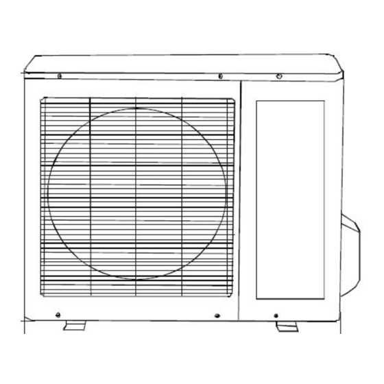
Page 5: Dimensions
ODMI-1103-A 3. Dimensions MODEL M2OC-14HRDN1-Q M2OC-14HRDN1 M2OC-18HRDN1 M2OC1-18HRDN1-Q M3OC1-21HRDN1-Q M3OC-27HRDN1 M3OC1-27HRDN1-Q M4OC-24HRDN1-Q M4OC-27HRDN1 M4OC1-27HRDN1-Q M4OC-36HRDN1-Q 1075 M5OA-36HRDN1-Q... -
Page 6: Wiring Diagram
ODMI-1103-A 4. Wiring Diagram 4.1 M2OC-14HRDN1-Q 4.2 M2OC-14HRDN1... - Page 7 ODMI-1103-A 4.3 M2OC1-18HRDN1-Q 、M3OC1-21HRDN1-Q 4.4 M2OC-18HRDN1、M3OC-27HRDN1...
- Page 8 ODMI-1103-A 4.5 M3OC1-27HRDN1-Q、M4OC-24HRDN1-Q 4.6 M4OC1-27HRDN1-Q、M4OC-27HRDN1...
- Page 9 ODMI-1103-A 4.7 M4OC-36HRDN1 4.8 M5OA-36HRDN1-Q...
-
Page 10: Refrigeration Cycle Diagram
ODMI-1103-A 5. Refrigeration Cycle Diagram 5.1 Refrigeration circuit drawing of inverter binary type 4.2 Refrigeration circuit drawing of inverter trinary type 5.3 Refrigeration circuit drawing of inverter quadplex type... - Page 11 ODMI-1103-A 5.4 Refrigeration circuit drawing of inverter quintuple type...
-
Page 12: Indoor Units Combination
ODMI-1103-A 6. Indoor units combination Indoor unit combination for M2OC-14HRDN1-Q、M2OC-14HRDN1 One unit Two unit 9+12 7+12 Note: There should be no more than one cassette or duct or console or ceiling & floor unit. Indoor unit combination for M2OC1-18HRDN1-Q、M2OC-18HRDN1 One unit... - Page 13 ODMI-1103-A 6.6 Indoor unit combination for M4OC1-27HRDN1-Q、M4OC-27HRDN1 One unit Two unit Three unit Four unit 12+12 7+7+7 7+9+12 9+9+9 7+7+7+7 7+7+9+9 7+9+9+12 9+12 12+18 7+7+9 7+9+18 9+9+12 7+7+7+9 7+7+9+12 7+9+12+12 7+12 9+18 18+18 7+7+12 7+12+12 9+9+18 7+7+7+12 7+7+12+12 9+9+9+9 7+18 7+7+18 7+12+18 9+12+12...
-
Page 14: Electronic Control Function
ODMI-1103-A Electronic control function 7.1 Abbreviation T1: Indoor ambient temperature T2: Coil temperature of indoor heat exchanger middle. T2B: Coil temperature of indoor heat exchanger outlet. T3: Coil temperature of outdoor heat exchanger T4: Outdoor ambient temperature T5: Compressor discharge temperature Ts: Setting temp. - Page 15 ODMI-1103-A EXV open angle for 1# indoor unit Actual data/8 EXV open angle for 2# indoor unit Actual data/8 EXV open angle for 3# indoor unit Actual data/8 EXV open angle for 4# indoor unit Actual data/8 Power supply of outdoor unit AD data Indoor unit number The indoor unit can communicate with outdoor unit well.
- Page 16 ODMI-1103-A A indoor unit evaporator outlet temp.(T B indoor unit evaporator outlet temp.(T C indoor unit evaporator outlet temp.(T If the temp.is lower than -9 degree, the digital display tube will show ¡-9¡.If the temp.is higher than 70 degree,the digital display D indoor unit evaporator outlet temp.(T tube will show ¡70¡.
- Page 17 ODMI-1103-A 7.4.3 Capacity demand: Cooling mode Capacity 2000-2 2000-2 3000-3 4500-5 5000-5 5500-6 6100-7 7000-7 7500-8 >7500 Correspondi >=10 ng Code Heating mode Capacity 2000-2 2000-2 3000-3 4500-5 5500-6 6100-7 6100-7 7000-7 7500-8 >8000 Correspondin 9-10 >=11 g Code Note: The capacity is just for reference.
- Page 18 ODMI-1103-A 7.4.4Number of indoor unit Display Number of indoor unit 7.4.5 Outdoor ambient temp: Corresponding Corresponding Display Corresponding temp. Display Display temp. temp. -7.5 10.5 25.5 -6.5 11.5 26.5 -5.5 11.5 27.5 -4.5 12.5 28.5 -3.5 13.5 29.5 14.5 -1.5 30.5 15.5 -0.5...
- Page 19 VOLREL1 No limit VOLLIMT1 VOLFRE1 VOLREL2 VOLLIMT2 VOLFRE2 VOLREL3 VOLLIMT3 Mode VOLLIMT1(V) VOLLIMT2(V) VOLLIMT3(V) VOLREL1(V) VOLREL2(V) VOLREL3(V) VOLFRE1(Hz) VOLFRE2(Hz) M2OC-14HRDN1 M2OC-14HRDN1-Q M2OC-18HRDN1 M2OC1-18HRDN1-Q M3OC1-21HRDN1-Q M3OC-27HRDN1 M3OC1-27HRDN1-Q M4OC-24HRDN1-Q M4OC-27HRDN1 M4OC1-27HRDN1-Q M4OC-36HRDN1-Q For M5OA-36HRDN1-Q, VOLTAGE No limit VOLT_RST1_ADD VOLT_LTM1_ADD VOLT_LTM_FREQ1_ADD VOLT_RST2_ADD VOLT_LTM2_ADD...
- Page 20 ODMI-1103-A VOLT_RST1_ADD=210V, VOLT_LIM1_ADD=200V, VOLT_RST2_ADD=195V, VOLT_LIM2_ADD=185V. VOLT_LIM_FREQ1_ADD=54Hz, VOLT_LIM_FREQ2_ADD=42Hz. 7.5.4 Compressor current limit protection If the compressor current exceeds the current limit value for 10 seconds, the compressor frequency will be limited as below table. For models except M5OA-36HRDN1-Q. Cooling mode: Current frequency(Hz) Current limit value(A) Frequency limit COOL_F10...
- Page 21 ODMI-1103-A COOL_F9 ICOOLLMT5 COOL_F8 ICOOLLMT4 COOL_F7 ICOOLLMT3 COOL_F6 ICOOLLMT2 COOL_F5 ICOOLLMT1 If the current frequency is lower than COOL_F4, the frequency will not be limited. After 10s of the compressor start, if the current>ICOOL,the AC will display the failure for 30 seconds and stop.
- Page 22 ODMI-1103-A If the compressor frequency keeps lower than RECOILINFRE for Te minutes,the AC will rise the frequency to RECOILFRE for Tf seconds and then resume to former frequency.For M4OC-36HRDN1-Q, RECOILINFRE=45Hz, RECOILFRE=48Hz,Te=120,Tf=180; For M5OA-36HRDN1-Q, RECOILINFRE=45Hz, RECOILFRE=48Hz, Te=90,Tf=100; For other models, RECOILINFRE=50Hz, RECOILFRE=62Hz, Te=120,Tf=180.
-
Page 23: Troubleshooting
ODMI-1103-A 8. Troubleshooting Indoor unit error code explanation: R series(except model MSR1I-07HRDN1-Q&MSR1I-09HRDN1-Q)+X series+Y series: Display MALFUNCTION EEPROM parameter error Indoor / outdoor units communication protection Zero-crossing signal error Fan speed out of control Open or short circuit of outdoor temperature sensor Open or short circuit of room or evaporator temperature sensor IGBT over-strong current protection Over voltage or too under voltage protection... - Page 24 ODMI-1103-A Cassette/Ceiling&Floor series: Operation Timer De-frost Alarm LED STATUS Indoor room temp. sensor open or short-circuit ★ Indoor pipe temp. sensor open or short-circuit Indoor and outdoor communication error ★ Water level alarm EEPROM error ...
- Page 25 ODMI-1103-A Outdoor unit error code explanation: For units(except M5OA-36HRDN1-Q model) Display LED STATUS EEPROM error No A Indoor unit coil outlet temp. sensor or connector of sensor is defective No B Indoor unit coil outlet temp. sensor or connector of sensor is defective No C Indoor unit coil outlet temp.
- Page 26 ODMI-1103-A For M5OA-36HRDN1-Q model Display LED STATUS EEPROM error Communication malfunction between outdoor unit and indoor units Communication malfunction between outdoor main chip and compressor control chip. Outdoor unit temp. sensor or connector of temp. sensor is defective Compressor voltage protection PFC module protection No A Indoor unit coil outlet temp.
- Page 27 ODMI-1103-A 8.3Trouble shooting 8.3.1 EEPROM parameter error diagnosis and solution Shut off the power supply and turn on it 5s later The problem comes out again Correct the connection Is the EEPROM chip plugged in PCB well? Replace the PCB 8.3.2 Indoor / outdoor units communication protection(Only for M5OA-36HRDN1-Q model) Disconnect the power supply, after 1 minute, connect the power supply , turn on...
- Page 28 ODMI-1103-A 8.3.3 Zero-crossing signal error Is power supply and Be sure the power supply connection is good and correct the connectors good? connection Indoor PCB is defective. Replace the indoor PCB. 8.3.4 Fan speed out of control diagnosis Shut off the power supply and turn on it 5s later The unit does not work normally Turn off the unit, rotate the indoor Disassemble...
- Page 29 ODMI-1103-A 8.3.5 Open or short circuit of temperature sensor diagnosis and solution. Check the connections between the sensors and the PCB. Are the connections good? Replace the sensor and check if Replace outdoor PCB the errors happen again? 8.3.6 Compressor voltage protection Check the voltage of power supply, if the voltage is about 220V, turn off the power supply to indoor unit and turn it on again after 1 minute Does the trouble occur again?
- Page 30 ODMI-1103-A 8.3.7 Communication malfunction between outdoor main chip and compressor control chip. Check whether the IPM board has error display Replace the outdoor PCB Replace the IPM board Replace the electric control box...
- Page 31 ODMI-1103-A 8.3.8 Temperature protection of compressor discharge or compressor top. Does Reconnect and retest. connection compressor good? operate? refrigerant protector circulation Replace the protector. normal? volume normal? Check outdoor main Charge PCB. there refrigerant some problem? Replace the outdoor Is abnormality PCB.
- Page 32 ODMI-1103-A 8.3.9 Compressor current protection Check the resistance of compressor, is it normal? The compressor is defective Turn one indoor unit only, Does the compressor start after 3 minutes? The compressor is defective Does the trouble occur again after compressor running some time? Check the refrigerant circulation volume and pressure If refrigerant circulation volume and pressure is OK, change the outdoor main PCB.
- Page 33 ODMI-1103-A 8.3.10 Inverter module protection Are the U,V,W connected to compressor and inverter module right? Repair connector Replace the IPM board If the problem comes to again, check wingding resistance of inverter compressor, is it right? Replace inverter compressor 8.3.11 Condenser high-temperature protection When outdoor pipe temp.
- Page 34 ODMI-1103-A 8.3.12 PFC module protection Check the voltage of power supply, if the voltage is about 220V, turn off the power supply and turn it on again after 1 minute Does the unit work normally ? Check whether the power supply of bridge Replace the rectifiers input port is outdoor PCB...
- Page 35 ODMI-1103-A Annex 1 Characteristic of temp. sensor Temp.℃ Resistance KΩ Temp.℃ Resistance KΩ Temp.℃ Resistance KΩ 62.2756 14.6181 4.3874 58.7079 13.918 4.2126 56.3694 13.2631 4.0459 52.2438 12.6431 3.8867 49.3161 12.0561 3.7348 46.5725 11.5 3.5896 10.9731 3.451 41.5878 10.4736 3.3185 39.8239 3.1918 37.1988 9.5507...
- Page 36 ODMI-1103-A Annex 2 1. Reference voltage data: Rectifier : Input :220-230V(AC), output :310V(DC) Inverter module: U,V, W 3ph. Result 60-150V(AC) 60-150V(AC) 60-150V(AC) 310V Photo-couple PC817, PC851: Control side <+5V, AC side :< 24V(AC) S terminal and N: changeable from 0-24V 2.
Need help?
Do you have a question about the M2OC-14HRDN1 and is the answer not in the manual?
Questions and answers