Table of Contents
Troubleshooting

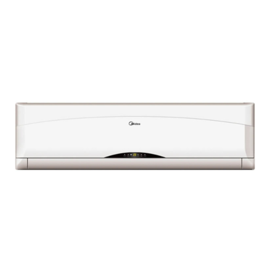
Summary of Contents for Midea MSCI-09HRN1
- Page 1 Draft edition GD Midea Refrigeration Equipment Co.,Ltd MULTI SPLIT TYPE, HEAT PUMP AIR CONDITIONERS Technical service manual 2005 R410A Corona multi Series Indoor Models MSCI-09HRN1 MSCI-12HRN1 Outdoor Models M2OA-18HRN1 M2OA-21HRIN1 M3OA-27HRN1 M2OA-30HRIN1...
-
Page 2: Troubleshooting
Multi SERIES 1. Features 2. Specification 3. Dimensions 4. Refrigeration cycle diagram 5. Operation limits 6. Wiring diagram 7. Troubleshooting 8. Electronic function 9. Exploded view parts 10. Characteristic of temp. sensor... - Page 3 1.Features 1.1 Compact design 1.2 High efficiency and quiet operation 1.3 Unitary outdoor unit design...
- Page 4 2 Specification 2.1 Indoor unit Corona multi indoor unit Model MSCI-09HRN1 MSCI-12HRN1 Model CE-KFR26G/CTN1Y CE-KFR32G/CTN1Y Power supply Ph-V-Hz 1Ph,220-240V~,50Hz 1Ph,220-240V~,50Hz Cooling Capacity BTU/h 9000 12000 Heating Capacity BTU/h 11000 13000 Capacity Running Current 0.18 Design Pressure (Hi/Lo) 4.2/2.5 4.2/2.5 Max. Operating Pressure (Hi/Lo) 3.5/3.5...
- Page 5 2.2 Outdoor unit Model M2OA-18HRN1 M2OA-21HRN1 M3OA-27HRN1 M3OA-30HRN1 Power supply Ph-V-Hz 1Ph,220-240V~,50Hz 1Ph,220-240V~,50Hz 1Ph,220-240V~,50Hz 1Ph,220-240V~,50Hz Capacity Btu/h 9000x2 9000+12000 9000x3 9000x2+12000 Input 890x2 890+1250 1650+1150 1800+1300 Cooling Rated current 4.0x2 4.0+5.7 8.0+5.5 8.2+5.8 Btu/w.h 10.2 Capacity Btu/h 1000x2 10000+14000 10000x3 10000x2+1300 Input 890x2...
- Page 6 Brand Welling Welling Welling Welling motor Input Capacitor 4uFx2 4uFx2 4uFx2 4uFx2 Speed r/min 830/650 830/650 1150 1150 a.Number of rows b.Tube pitch(a)x 25.4x24 25.4x24 25.4x24 25.4x24 pitch(b) c.Fin spacing d.Fin type (code) Hydrophilic aluminium Hydrophilic aluminium Hydrophilic aluminium Hydrophilic aluminium Outdoor coil e.Tube outside dia.and type...
- Page 7 Plug type Thermostat type Electronic control Electronic control Electronic control Electronic control Operation temp ℃ 17~30 17~30 17~30 17~30 18~45(cooling); Ambient temp 18~45(cooling); -7~30(heating) 18~45(cooling); -7~30(heating) 18~45(cooling); -7~30(heating) ℃ -7~30(heating) Application area (14-21)x2,16-24 (14-21)x2,16-24 (14-21)x2,16-24 (14-21)x2,16-24 Qty’per 20’ /40’ /40'HQ 45/94/118...
- Page 8 3.Dimensions 3.1 Indoor unit a) Indoor unit 9K b) Indoor Unit 12K...
- Page 9 3.2 Outdoor unit a) Outdoor unit 18K/21K b) Outdoor unit 27K/30K...
- Page 10 4.Refrigeration cycle diagram “1 drive 3 system” is made up of one “1 drive 1 system” and one “1 drive 2 system”. PMV1 PMV2 2# 1# Compressor refrigeration distributor 1 drive 2 system SV1: Primary four-way valve SV2: Secondary four-way valve PMV1,...
-
Page 11: Heating Operation
5.Operation limits 5.1Cooling operation Outdoor unit air temp. ℃ DB COOLING Indoor air temp. ℃ DB Note : The chart is the result from the continuous operation under constant air temperature conditions. However, excludes the initial pull-down stage. 5.2Heating operation Indoor air temp. - Page 12 6.Wiring diagram Indoor unit CORONA INDOOR UNIT Outdoor unit FOR 1 DRIVE 2 OUTDOOR UNIT...
- Page 13 FOR 1 DRIVE 3 OUTDOOR UNIT...
-
Page 14: Outdoor Unit
7.Troubleshooting 7.1 Indoor unit Failure phenomenon Operation lamp Timer lamp Indoor fan speed has been out of control for over 1 minute ☆ Indoor room temp. sensor or evaporator temp. sensor is open circuit ☆ or short circuit EEPROM error ☆... -
Page 15: Temperature Indicator
8 Electronic function Electric Control working environment 8.1.1 input voltage: 175~253V 8.1.2 Input power frequency:50Hz 8.1.3 Ambient temperature: -7°C~+43°C 8.1.4 Indoor fan normal working amp is less than 1A, 8.1.5 Outdoor fan. Normal working amp is less than 1.5A 8.1.6 Four-way valve normal working amp is less than 1A. - Page 16 TE7: Evaporator high temperature protection, compressor off temperature TE8: Evaporator high temperature protection, fan off temperature TE9: Evaporator high temperature protection, restoring temperature T3: Outdoor unit pipe sensor T4: Outdoor temperature sensor Systematic functions. Remote receiving. Testing and forced run. Position set for indoor unit wind vane.
- Page 17 Protection 8.5.1 The compressor functions protection with a delay of three minutes. 8.5.2 High temp. protection of condenser. 8.5.3 Sensor protection at open circuit and breaking disconnection 8.5.4 Temperature Fuse break protection 8.5.5 Fan Speed is out of control. When Indoor Fan Speed is too high(higher than High Fan+300RPM)or too low(lower than 400RPM), the entire unit stops and LED displays failure information and can’t returns to normal operation automatically.
- Page 18 compressor, indoor fan run 5 minutes in low speed. And repeat on and off cycle. 8.8.3 Low room temperature protection: When room temperature decreases to below 10℃, the compressor and the outdoor fan will stop(indoor fan is Breeze). Dehumidifying operation will be resumed when room temperature restores to over 13℃.
- Page 19 8.9.5 Auto wind under heating mode Condition Indoor fan speed T=Indoor Temp.-Setting Temp. Room temp. up T<2℃ High T>2℃ Med. Room temp. down T> 0℃ Med. T<0℃ High 8.9.6 Indoor evaporator high-temperature protection under heating mode Condition Compressor Outdoor fan Indoor exchanger temp.
- Page 20 8.11 Automatic operation mode 8.11.1 The air conditioner automatically selects one of the following operation modes: cooling, heating or ventilation according to the difference between room temp. (TA) and set temp. (TS). TA—TS Operation mode TA—TS>2℃ Cooling -1 ≤TA —TS≤+2℃ Fan-only ℃...
- Page 21 8.16 Outdoor fan motor T4: Outdoor temp. Outdoor fan motor Cooling mode T4>27℃ High speed T4<25℃ Low speed Heating mode T4>13℃ Low speed T4<11℃ High speed...
-
Page 22: Indoor Unit
Exploded view parts a) INDOOR UNIT... -
Page 23: Universal Outdoor Unit
b) UNIVERSAL OUTDOOR UNIT... - Page 25 10. Characteristic of temp. sensor Temp.℃ Resistance KΩ Temp.℃ Resistance KΩ Temp.℃ Resistance KΩ 62.2756 14.6181 4.3874 58.7079 13.918 4.2126 56.3694 13.2631 4.0459 52.2438 12.6431 3.8867 49.3161 12.0561 3.7348 46.5725 11.5 3.5896 10.9731 3.451 41.5878 10.4736 3.3185 39.8239 3.1918 37.1988 9.5507 3.0707 35.2024...


Need help?
Do you have a question about the MSCI-09HRN1 and is the answer not in the manual?
Questions and answers